The USB current and voltage detection and testing device, based
on the ESP32-PICO-D4+INA226, uses a Type-C connector and is powered by the ESP32-PICO-D4 chip. It employs the INA226 for voltage and current measurement
and features a 0.96-inch TFT display showing voltage, current, power, and capacity.
Input and output are via Type-C connectors, supporting PD fast charging.
A USB-to-serial adapter cable is required and should be soldered to the pre-installed pads on the board.

PDF_usb current and voltage detection.zip
Altium_usb current and voltage detection.zip
PADS_usb current and voltage detection.zip
BOM_usb current and voltage detection.xlsx
92071
Sky Star Extension Board
This extended version is primarily designed for learners with many independent modules requiring 3.3V or 5V power. It allows for easy power selection, and the rearranged layout makes it easy to locate the GPIO. It also features four independent buttons, three LEDs, a buzzer, an MPU6050, and a screen.
This extended version is mainly intended for users with many independent functional modules that require 5V or 3.3V power. The voltage is selected using the jumper cap on the right side of the lead-out pins. The screen can be fixed to the SkyStar board using double-sided foam tape, but the screen's FPC will block the memory card. You can reinstall the screen after installing the memory card (tweezers are required).
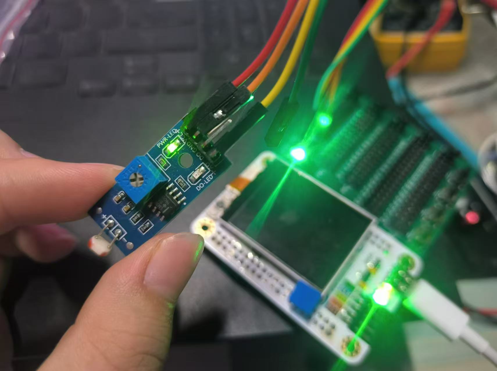
The board has a surface-mount 6050, a buzzer, and a screen driver circuit, allowing for small acceleration or gesture-based applications, such as a gravity-sensing game console or menu selection controlled by acceleration
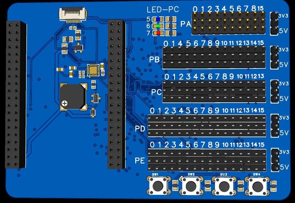
. (I forgot to take pictures during installation, so here's a 3D image).
The screen can be fixed to the SkyStar board using double-sided foam tape, but the screen's FPC will block the memory card. You can reinstall the screen after installing the memory card (tweezers are required).

The screen does not block the three onboard buttons on the SkyStar board. Resetting and downloading do not require re-leading
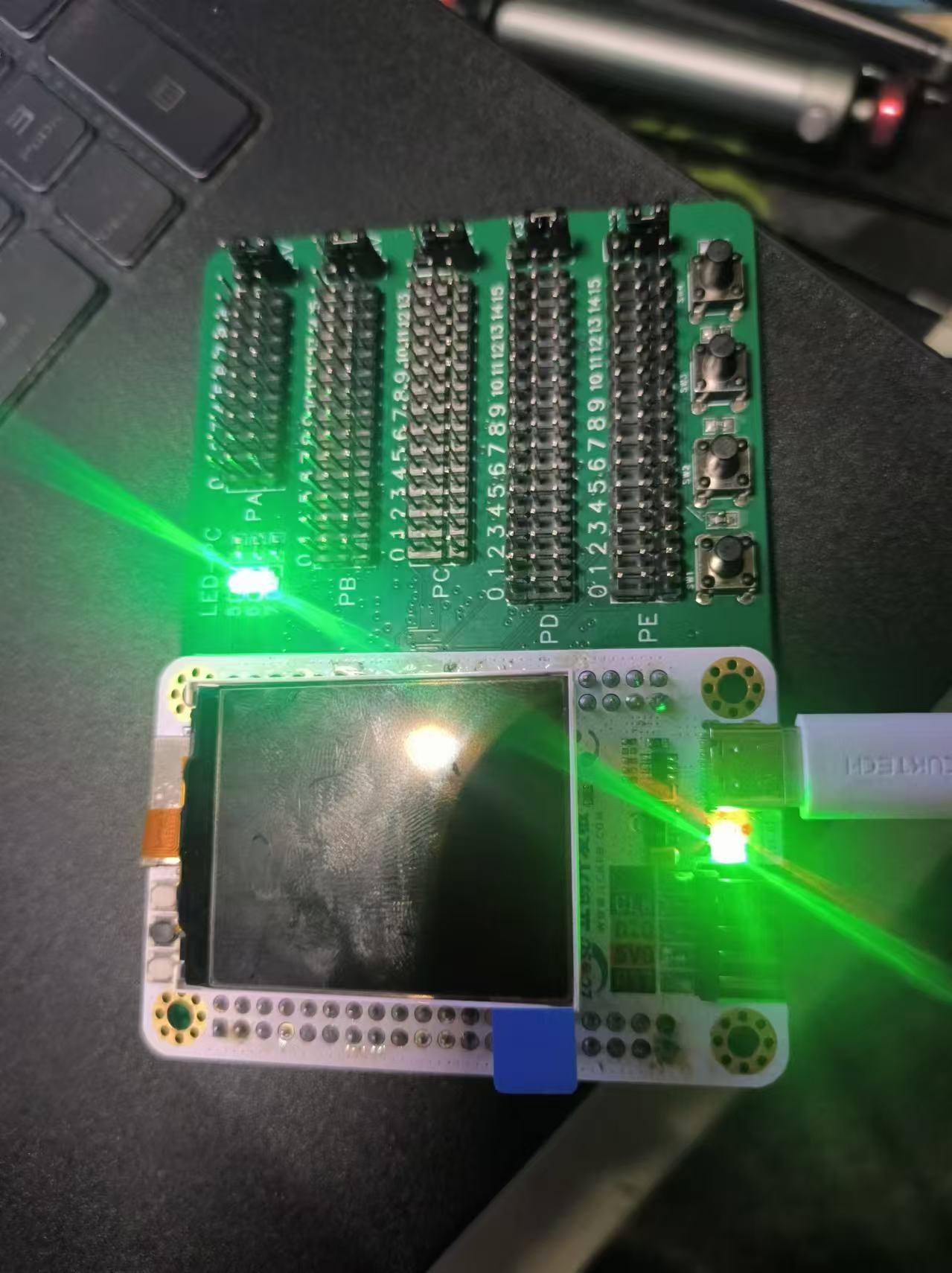
the screen. The test program is not yet written. Except for the screen and 6050, other components are working normally. The 6050 seems to have a cold solder joint; I'll try resoldering it with a bare board after some time. Updates will follow after testing.
PDF_SkyStar Extension Board.zip
Altium_SkyStarExtensionPad.zip
PADS_SkyStar Expansion Board.zip
BOM_SkyStar Expansion Board.xlsx
92075
Purple Lightning Divine Sword with Handheld Ultraviolet Disinfection Lamp
A handheld ultraviolet disinfection lamp for surface sterilization. Use with caution as it is relatively dangerous. While the project was successfully completed, many aspects are still imperfect; this is only provided for reference, please attempt to replicate it with caution.
A handheld UV sterilization lamp for surface disinfection. It is relatively dangerous to use; please use with caution. While the project was successfully completed, many aspects are still imperfect. This is only provided for reference; please attempt to replicate it with caution. An introductory video is available on Bilibili.

4ce77d5cfc66524f6e2d2af8c86ce051.mp4
PDF_Handheld UV Disinfection Lamp with Purple Lightning Sword.zip
Altium_Handheld UV Disinfection Lamp with Purple Lightning Sword.zip
PADS_Handheld UV Disinfection Lamp - Purple Lightning Sword.zip
BOM_Handheld UV Disinfection Lamp with Purple Lightning Sword.xlsx
92076
ETA6002
Single-cell 18650 battery power management module based on ETA6002
The schematic diagram references a successfully verified project
simulating battery input and
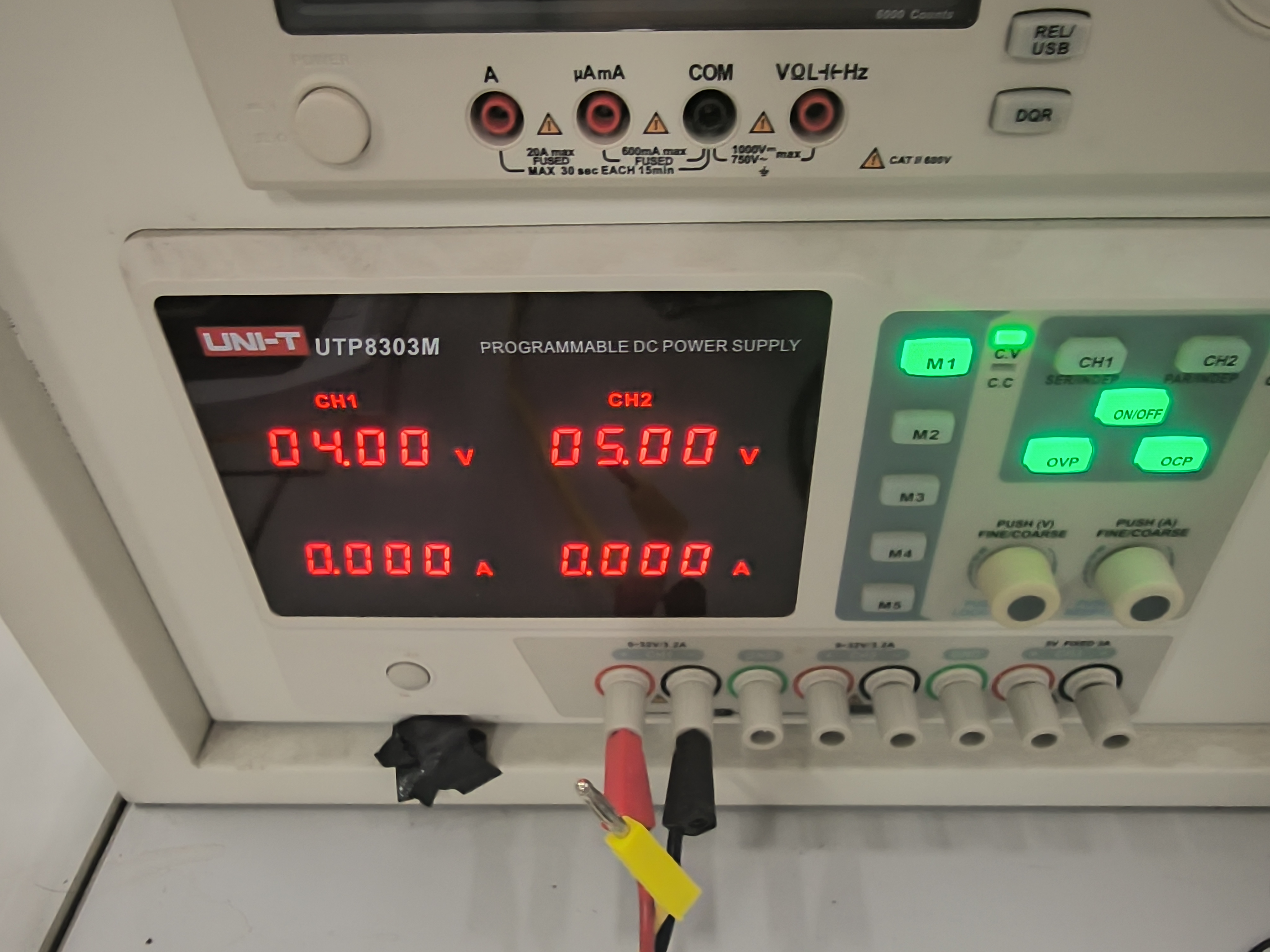
output voltage .

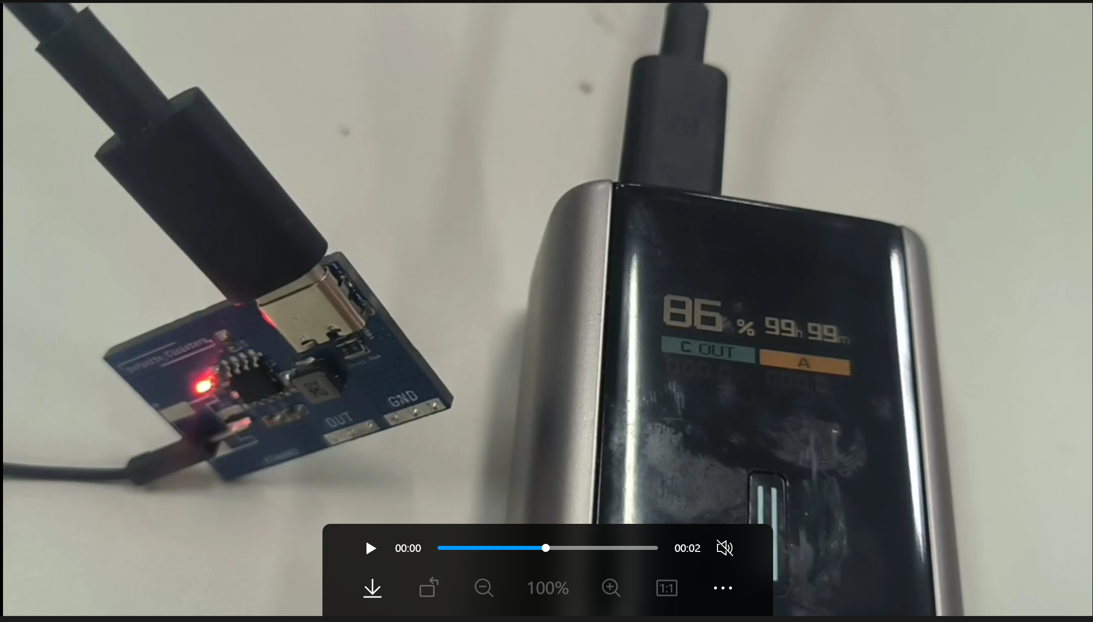
It's evident that the chip can draw power directly from the battery without external power.
Without external power, the LED will blink (screenshot from video).
This open-source PCB layout references the official recommended layout.
0dcb41691c7576d8d1ea1d819554b0e6.mp4
PDF_ETA6002.zip
Altium_ETA6002.zip
PADS_ETA6002.zip
BOM_ETA6002.xlsx
92078
Pi_Pico_Rx
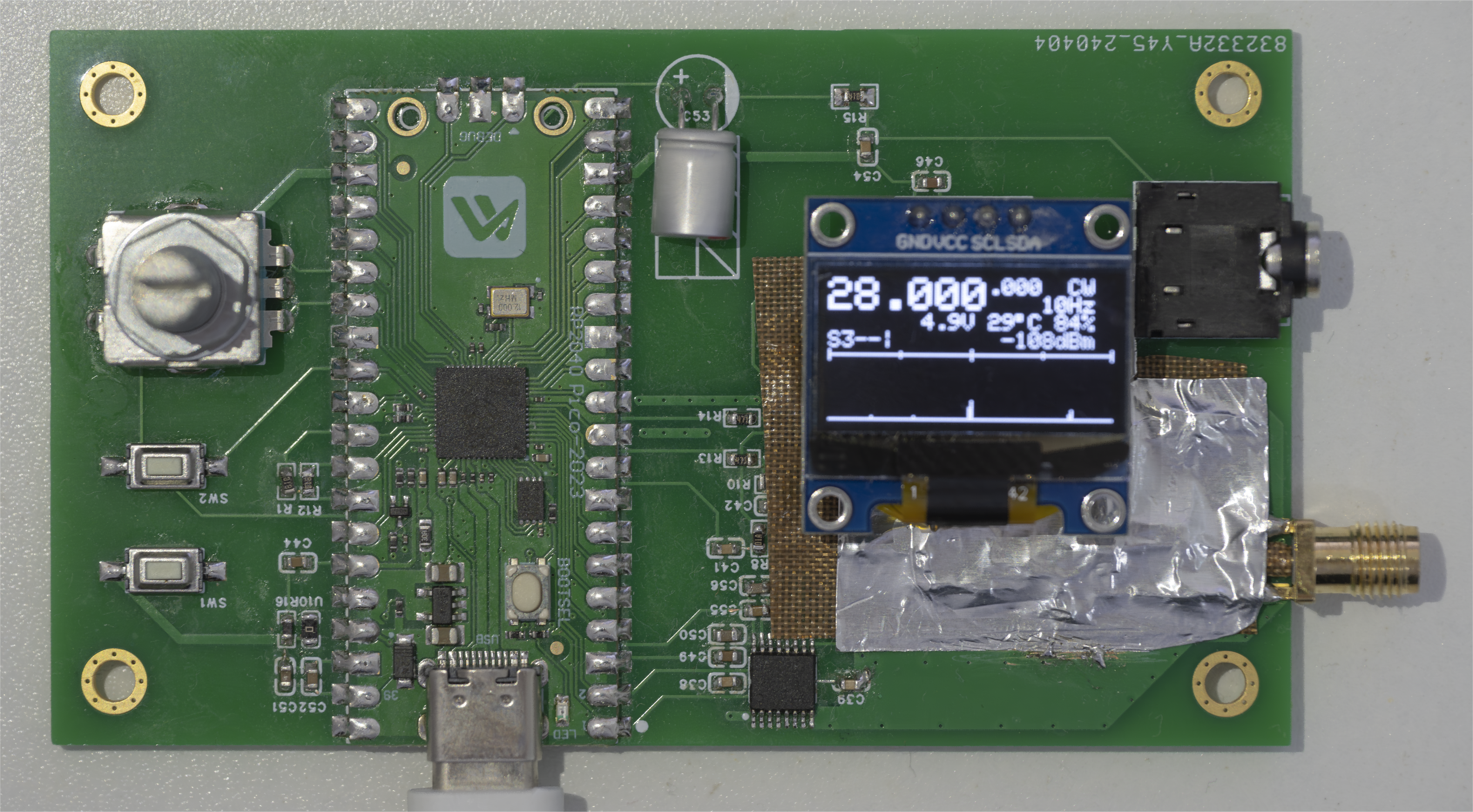
Pi Pico RX
Pi Pico RX, original project address https://github.com/dawsonjon/PicoRX, has a simplified power supply circuit. The grounding area of the filter section is too large, making it difficult to solder with a soldering iron; a hot plate can be used if available.
PDF_Pi_Pico_Rx.zip
Altium_Pi_Pico_Rx.zip
PADS_Pi_Pico_Rx.zip
BOM_Pi_Pico_Rx.xlsx
92079
electronic


 京公网安备 11010802033920号

 BAT64-04


