Introduction:
The BQ24640 is a 600kHz switching frequency, NMOS-NMOS synchronous buck topology supercapacitor charging controller. It supports 5-28V input voltage and 2.1-26V output voltage. It features CC-CV mode switching, supports 0V start-up charging for supercapacitors and other devices, supports charging currents up to 10A while maintaining efficiency above 90%, and supports high-temperature capacitor protection. In sleep mode, when the input voltage is removed, the capacitor current drops to as low as 15uA, reducing energy consumption.
Key Components/Replica Considerations:
1. I used the APG068N04G MOSFET, which costs about 60 cents each on Taobao. It has a 40V withstand voltage, an on-resistance of less than 6.8mΩ at 10Vgs, and a Ciss of 840pF. In actual testing, the on-resistance seemed a bit high, but the BQ24640 drove it reasonably well. A MOSFET with a larger Ciss could probably be used instead.
2. The surface-mount power inductor is a common 1770 package molded shielded surface-mount inductor found on Taobao, with a capacity of 6.8uH. While slightly bulky, its measured temperature rise at 9.5A is not high. In practical applications, if size is a concern, a smaller package can be used, and the inductance value can be appropriately reduced (e.g., using 4.7uH or 3.3uH) if ripple requirements are not high.
3. For 10A applications, the official recommendation is to use at least two 47uF capacitors in parallel at the input and output. The capacitor connected in series with a resistor acts as an RC filter to prevent high-voltage spikes from generated by the parasitic inductance of the circuit during power supply, which could damage the MOSFET and the main control IC. In the RC filter for the main control I2C power supply, the value of R should not be too large; the official recommendation is 4.7-30 ohms, and the package should be 0805 or 1206.
4. For the current sampling resistor, attention needs to be paid to power rating and temperature drift. Actual testing showed that for a 10A application, a 5mΩ, 2512 packaged current sampling resistor exhibits a significant temperature rise (reaching 60-70°C) at room temperature (23°C). This may cause malfunction when the current approaches the set overcurrent protection current; caution is advised.
5. For the MOSFET drive circuit, fast recovery diodes should be used. For this layout, a 2-ohm gate drive resistor is sufficient to obtain a good gate drive waveform. Other layouts require actual testing and adjustments.
Measured Data:
All test conditions for the following data are:
1. Room temperature 23°C
2. 12V to 5.2V, electronic load constant current mode
3. Test instruments:
Oscilloscope: Hantek DSO2C15
Power supply: ETM3010P
Electronic load: DCL8003+
Thermal imager: IRay C210
Due to limited personal time and expertise, it is impossible to control too many variables; therefore, this data is for reference only.
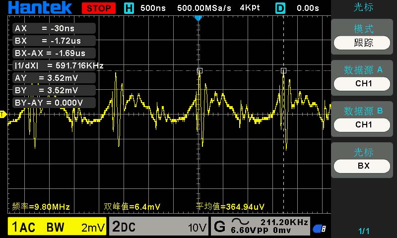
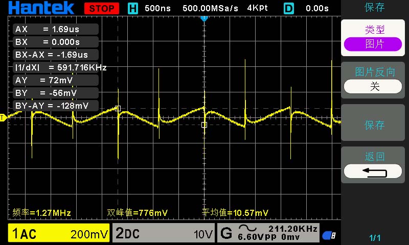
1. MOSFET gate drive waveform:
High-side MOSFET (to ground)

Low-side MOSFET (to ground)
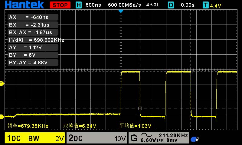
(Since the waveforms remain basically unchanged across power ranges, only one set is tested.)
The following are constant current tests, showing the input and output voltages respectively. Some include thermal images after temperature stabilization.
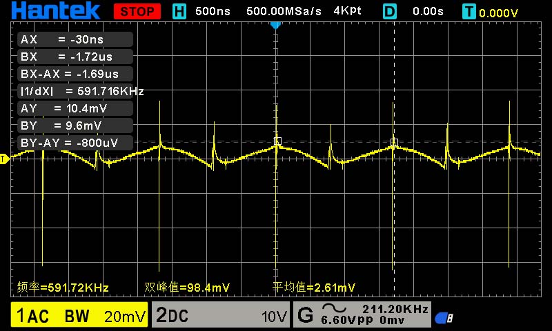
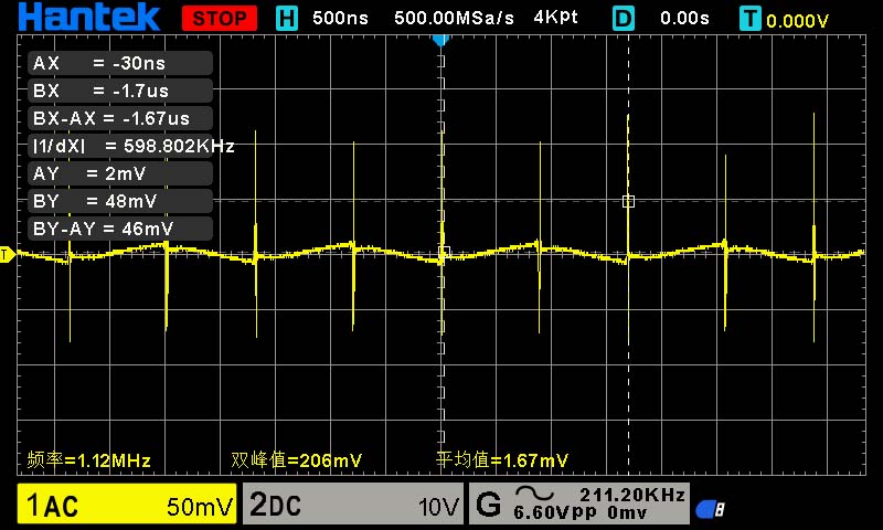
1A load constant current test:
Input:
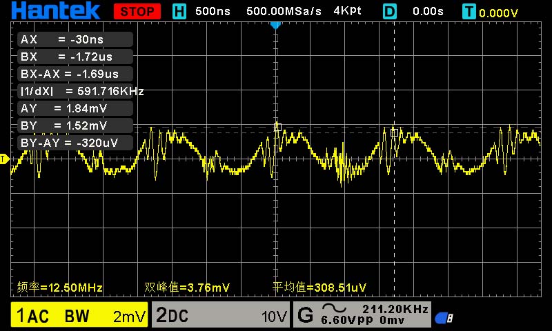
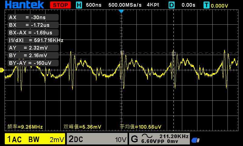
Output:
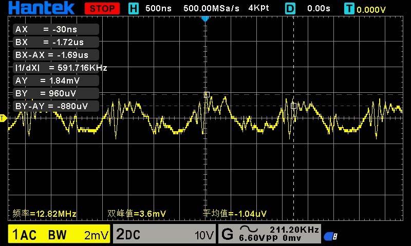
(These are indeed the values; it's not due to poor contact or something not being measured, because if there were poor contact and it wasn't measured, the induced noise would be much greater.)
3A load:
Input: Output

:
5A load: Input:
Output

:

7A load:
Input:
Output:
8A load:
Input:

Output:
9A load:
Output:

9.5A load: Input
: Output

:

Long-term temperature rise:
Under a 9A load for 30 minutes, the upper transistor
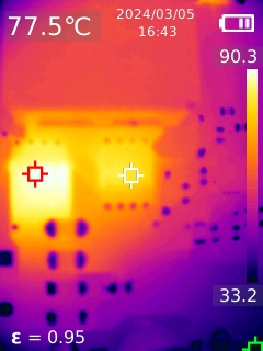
experienced the largest temperature rise: The upper transistor reached approximately 90 degrees Celsius, and the lower
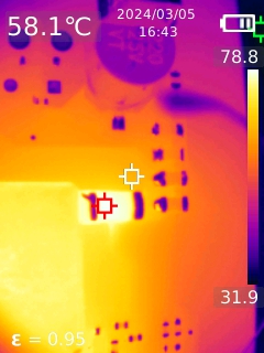
transistor reached approximately 77 degrees Celsius. The current sampling resistor also had a significant temperature, nearly 80 degrees Celsius. At 9.5A, the temperature drift of the sampling resistor increased further, causing the main controller to misjudge overcurrent and shut down, making testing impossible. For extended use, it is recommended to
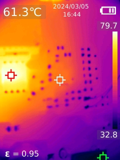
keep the current below 9A; the main controller IC remains relatively cool, at only around 61 degrees Celsius. It seems a transistor with a larger ciss and lower on-resistance could be used.
The inductor, being a metal, has a different emissivity, requiring thermocouple temperature measurement, which showed a temperature of around 65 degrees Celsius, relatively cool.
Another precaution:
When using constant current mode with an electronic load, if overcurrent protection is accidentally triggered, causing the IC to hiccup and start, the lower transistor and IC temperatures will rise rapidly during low-voltage output, potentially causing burnout!


 京公网安备 11010802033920号

 RN73H2ETTE1231B10


