I. Design Background
Learning to design and build a digital voltmeter and ammeter is highly beneficial for improving one's professional skills. This simple digital voltmeter and ammeter project covers multiple aspects, including microcontroller circuit design and implementation, signal acquisition and processing circuit design, user interface development and optimization, and product appearance design. It integrates knowledge from multiple fields such as electronics, microcontroller programming, circuit design, and industrial design. This introductory digital voltmeter and ammeter project is very suitable for beginners in electronics and those who want to learn more about microcontroller applications. This project was completed under the guidance of engineers from LCSC, Chipsource, and experts in WeChat groups. Sincere thanks are extended to all the experts involved. This project has the following highlights:
It adopts a core board plus expansion board design concept, making learning simpler and exploration more in-depth;
the core board uses the domestic Wuhan Chipsource Semiconductor CW32 as the main controller, while also being compatible with other similar development boards; however, the CW32 has advantages.
The project is highly comprehensive and practical, and can be used as a desktop instrument after completion;
the project has abundant learning materials, including circuit design tutorials, PCB design, code programming learning, and training for engineers' debugging abilities.
II. Selection
1. MCU Selection Analysis

Clearly define project requirements: Understand the required computing power, including clock speed, processor core type, and whether a floating-point unit is needed.
Identify the required I/O ports and important peripherals, such as the ADC peripheral. Since this is a development board project, the main purpose is debugging and learning; therefore, there are no strict limitations on the number of I/O ports, i.e., cost issues are not considered.
Key advantages of CW32 in this project:
Wide operating temperature range: -40~105℃;
Wide operating voltage range: 1.65V~5.5V (STM32 only supports 3.3V systems)
; Strong anti-interference: HBM ESD 8KV; All ESD reliability reaches the highest international standard level (STM32 ESD 2KV);
Project focus - Better ADC: 12-bit high-speed ADC, achieving ±1.0LSB INL 11.3ENOB; Multiple Vref reference voltages... (STM32 only supports VDD=Vref);
Stable and reliable eFLASH technology.
2. Power Supply Circuit

: This project uses an LDO as the power supply. Considering that most voltmeter products are used in industrial scenarios with 24V or 36V power supplies, the SE8550K2 with a maximum input voltage of up to 40V was selected as the power supply.
3. Voltage Sampling Circuit : The voltage
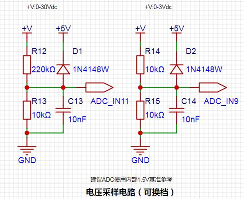
divider resistors in this project are designed to be 220K+10K, therefore the voltage division ratio is 22:1 (ADC_IN11).
The voltage divider resistor selection
is designed to measure the maximum voltage value; for safety reasons, this project uses 30V (the actual maximum display can be 99.9V or 100V).
The ADC reference voltage is 1.5V in this project, and this reference voltage can be configured through the program.
To reduce the power consumption of the sampling circuit, the low-side resistor (R13) is usually chosen as 10K based on experience.
Then, the high-side resistance of the voltage divider resistor can be calculated using the above parameters.
The required voltage division ratio is calculated, i.e., the ADC reference voltage. The input voltage is designed; using known parameters, 1.5V/30V = 0.05 can be calculated.
The high-side resistance is calculated as the low-side resistance/voltage division ratio; using known parameters, 10K/0.05 = 200K can be calculated.
A standard resistor is selected: a resistor slightly higher than the calculated value of 200K is chosen. We usually choose E24 series resistors; therefore, in this project, 220K, which is greater than 200K and closest to the calculated value, is selected.
If, in actual use, the voltage to be measured is lower than 2/3 of the module's design voltage (66V), the voltage divider resistor can be replaced and the program modified to improve measurement accuracy. The following example illustrates this:
Assuming the measured voltage is no higher than 24V and other parameters remain unchanged,
calculations show 1.5V/24V = 0.0625, 10K/0.0625 = 160K. 160K is a standard E24 resistor and can be directly selected, or a higher value 180K can be chosen with some redundancy.
If, in actual use, the voltage to be measured is higher than the module's 99V design voltage, a different resistor can be selected. To achieve a wider voltage measurement range, one can choose to replace the voltage divider resistor or modify the reference voltage. The following example illustrates this:
Assuming the measured voltage is 160V, the solution is to increase the voltage reference to expand the range.
Given that the voltage division ratio of the selected resistor is 0.0145, we can calculate 160V * 0.0145 = 2.32V using the formula. Therefore, we can choose a 2.5V voltage reference to expand the range (increasing the range will reduce accuracy).
Considering the potential fluctuations in the measured power supply, a 10nF filter capacitor is connected in parallel with the low-side voltage divider resistor to improve measurement stability.
Range switching:
In this project, an additional voltage sampling circuit was added. Therefore, we can discuss the significance of range switching for improving measurement accuracy. Multimeters often have multiple range settings for more accurate measurements. By adjusting different ranges, the optimal measurement accuracy of the measured point within the corresponding range can be obtained.
This project requires a combination of hardware and software to achieve this function. When we first use the ADC_IN11 channel mentioned earlier to measure voltages below 30V... If the measured voltage is within 0~3V, use the ADC_IN9 channel for measurement. In this case, the measurement accuracy is greatly improved due to the reduced voltage division ratio.
There are many ways to implement range switching; the development board design provides more design possibilities.
4. Current Sampling Circuit

Note: When learning, please do not solder R0!!!
The design analysis
for this project involves a sampling current of 3A, and the selected sampling resistor (R0) is 100mΩ.
The selection of the sampling resistor mainly considers the following aspects:
the maximum value of the pre-designed measurement current;
the voltage difference caused by
the 3A current sensing resistor in this project; and the power consumption of the current sensing resistor, which should generally not exceed 0.5V. A suitable package should be selected based on this parameter. Considering the power consumption (temperature) issue under high current, a 1W package resistor was chosen
. The voltage amplification factor across the current sensing resistor is 1 since no operational amplifier is used in this project.
The current sensing resistor value can then be calculated using the above parameters.
Since no amplifier circuit is used in this project, a larger sampling resistor is needed to obtain a higher measured voltage for measurement. However,
considering that a larger resistor will result in a larger voltage difference and higher power consumption, an unlimited selection of a larger resistor is not possible.
A 1W package resistor was chosen in this project, corresponding to a power consumption rise of 1W.
Based on the above data, a 100mΩ current sensing resistor was selected. According to the formula, 3A * 100mΩ = 300mV, 900mW.
To handle different usage environments, especially high-current scenarios, resistor R0 can be replaced with constantan wire or a shunt, allowing for selection based on the specific application. For safety and educational purposes, this project will not delve into measurements exceeding 3A, but the principle remains the same.
5. Digital Tube Display
This project uses digital tubes as the display unit.

In this project, actual testing showed that the current-limiting resistors (R1~R6) for the digital tubes were configured to 300Ω, resulting in good visibility and a soft, non-glaring brightness.
Strictly speaking, the current-limiting resistors should be added to the segments; adding them to the digits would affect the display effect. In our actual design, we added them to the digits, saving a few resistors, but the impact on the display is not significant, so we still added them to the digits.
When calculating the current required for the digital tubes,

it is important to ensure that the selected MCU has sufficient current-source/current-sinking capabilities.

6. TL431 Circuit Design for Voltage Measurement and Calibration:

This project adds an extra TL431 circuit to provide a 2.5V reference voltage. This can be used to provide an external voltage reference for the chip to calibrate the AD converter. From a product design perspective, due to the inherent ADC performance advantages of the CW32, this circuit is not necessary. This circuit is designed on the development board for learning related application principles.
The TL431 is a relatively "old" device, a classic, and widely used one, still found in many electronic products.
TI defines it as a "Precision Programmable Reference." On the first page of the references, we can focus on several key characteristics:
Precision: Precision indicates that its output voltage is very accurate. At room temperature, the measured voltage on the board is 2.495V. Compared to common Zener diodes, the accuracy is vastly different. In the application circuit diagram, the TL431 is represented by a Zener diode symbol.
Adjustable Output Voltage: The adjustable output voltage is between Vref and 36V. In this project, we use the output Vref voltage, which is approximately 2.5V. Therefore, we use 2.5V in the description, which is approximately equal to 1mA.
Sinking current capability: This refers to how much current the output voltage pin can provide, which is greatly related to the resistance value (R16) in the application circuit. It should not be less than 1mA. If there is no need for sinking current, do not design the current too high, causing unnecessary power consumption.
III. Optimization and Debugging
Accuracy Optimization: Appropriate resistors, capacitors, and other components can be selected, and the sampling rate and resolution of the ADC can be optimized to improve the measurement accuracy of voltage and current.
Stability Optimization: The power management circuit and reverse connection protection circuit can be optimized to ensure stable operation of the system under various working environments.
Software Debugging: The software can be debugged and optimized using debugging tools to ensure the correctness and stability of data acquisition, processing, and display functions.
Data Analysis: In special applications, the algorithm can be modified or selected according to the actual signal interference.


 京公网安备 11010802033920号

 DS7830


