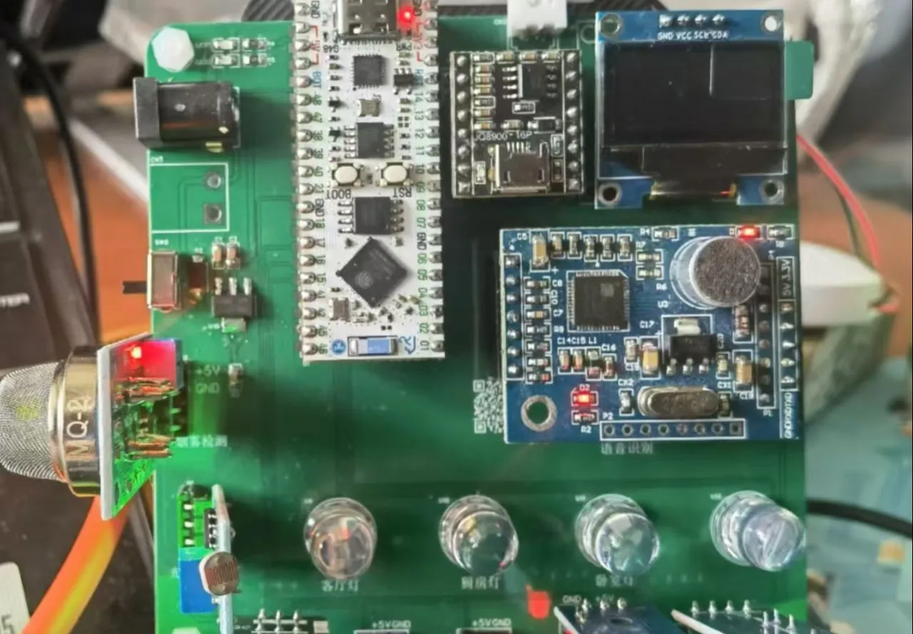
This is a smart home control system based on Espressif ESP32 with voice control. Its
main functions include:
1. Detecting air temperature and humidity; 2. Detecting light intensity; 3. Detecting air quality; 4. Uploading all data to Alibaba Cloud; 5. Displaying temperature, humidity, air quality, and time on an OLED screen; 6. Voice recognition control; 7. Customizable SMS receiving function; 8. Controlling bedroom lights, living room lights, kitchen lights, fans, and curtains; 9. Controllable via a mobile app and voice control.
The primary purpose is to learn about the JLCPCB ESP32S3R8N8 development board, so the plan is to create a smart home system. From this, one can learn about (one-wire serial port, serial port, SPI, PWM, analog-to-digital conversion, I2C, voice recognition, voice broadcasting, connecting to Alibaba Cloud, etc.).
II. Project Introduction Based on the ESP32 development board, a smart home system was designed. Its main functions include voice interaction, OLED display, cloud display, cloud control, and remote control. It can detect temperature, humidity, light, rain, and smoke in the home environment, and control bedroom lights, living room lights, kitchen lights, windows, and curtains. It can also obtain and display weather forecasts from the cloud.
III. Module Introduction 1. Main Controller: LCSC-ESP32S3R8N8 Development Board This is a fully domestically produced, fully open-source, high-performance development board made by JLCSC.
1.1 Features High-performance portable WIFI and Bluetooth development board, all materials are fully open source, rich tutorials and examples, easy to get started, project-based learning. Supports multiple development environments such as ESP-IDF, Arduino IDE, and MicroPython. Provides drivers for commonly used electronic modules and project examples. LCSC Open Source Website: LCSC Development Board Technical Documentation Center (lckfb.com) 2. Voice Recognition Module: LD3320-Serial Version The LD3320 voice recognition module is a powerful voice recognition solution with many advantages.
1.1 Key Features: No Model Training Required: The LD3320 integrates a pre-trained speech recognition system, saving users significant time and effort. You don't need to perform complex model training; you only need to know how to call the module. High Ease of Use: It functions like a complete module, similar to building blocks, requiring no extra steps and can be used directly. This makes it user-friendly even for those without in-depth expertise. Highly Efficient Recognition: It can quickly and accurately recognize specific voice commands, providing an efficient voice interaction experience for various application scenarios. 1.2 How We Use It in Our Project: Currently, there are two models of the LD3320 on the market: one is the serial port version, as shown in the diagram below. This is our main focus today; we can consider it as a module in the peripheral circuit (like a building block), requiring an external microcontroller to "call" this module to achieve intelligent speech recognition.
Its use is particularly simple. The following diagram shows the module's schematic.
The following diagram shows the interface for connecting to the module. Simply connect 5V, GND, TXD, and RXD to the microcontroller.
Specific usage details will be updated later.
3. Voice Broadcast Module: JQ8900-16P The JQ8900-16P voice module is powerful and comes with 32M of memory. It supports microcontroller serial port control and one-to-one button control, and can directly drive a 3W speaker. It has an interstitial mode to meet the needs of various scenarios. It is easy to operate, has stable performance, and provides an efficient solution for audio playback, making it an ideal choice for implementing voice functions in many devices.
Hardware connection is shown in the following figure
. 4. Display: 0.96-inch OLED Module The 0.96-inch 4-pin OLED screen module is a display module that includes a 0.96-inch OLED display and 4 pins. This type of OLED screen module is commonly used in embedded systems and small electronic devices to display text, images, and other types of information. Due to their small size and low power consumption, they are also commonly used in smartwatches, health trackers, and other portable devices. These modules typically use SPI or I2C interfaces for communication and support multiple resolutions and color modes.
Hardware connections are shown in Figure
5. Temperature and Humidity Sensor: DHT11. The DHT11 is a digital temperature and humidity sensor suitable for environmental monitoring. It uses a single-bus protocol, can simultaneously measure temperature and humidity, is compatible with 5V power supplies, and features simple wiring and low power consumption. The sensor has a built-in 8-bit microcontroller, and data transmission includes the integer and decimal parts of humidity and temperature, as well as checksums, ensuring data accuracy. Strict timing is required for data reading. Example programs for 51 and STM32 demonstrate how to communicate with the DHT11 to read and process data.
6. Smoke Sensor: MQ-2. The MQ-2 smoke sensor uses tin dioxide semiconductor gas-sensitive material, belonging to surface ion-type N-type semiconductors. When at 200~300 degrees Celsius, tin dioxide adsorbs oxygen from the air, forming negative oxygen ions, reducing the electron density in the semiconductor and thus increasing its resistance. When exposed to smoke, if the potential barrier at the grain boundaries changes due to the smoke's influence, it will cause a change in surface conductivity. This can be used to obtain information about the presence of the smoke; the higher the smoke concentration, the higher the conductivity, the lower the output resistance, and the larger the output analog signal, similar to the MQ-7.
This time, the MQ-2 sensor is used to monitor the concentration of CH4. The microcontroller reads the analog voltage signal output by the MQ-2 sensor via an ADC (analog-to-digital converter). First, the average value of the ADC over a certain period can be obtained. Second, the average value of the ADC can be converted into the output voltage value of the MQ-2 using a formula. Then, the concentration of CH4 can be calculated based on this voltage signal and the sensor's characteristic curve (i.e., the broken line with the yellow triangle in the above figure).
7. Raindrop Sensor This sensor has two output forms: digital switch output (0 and 1) and analog AO voltage output. When connected to a 5V power supply, the power indicator light is on. When there is no water droplet on the sensor board, the DO output is high, and the switch indicator light is off; when a drop of water is added, the DO output is low, and the switch indicator light is on; after the water droplet is wiped away, the output returns to a high level. The AO analog output can be connected to a microcontroller's AD port to detect the amount of raindrops falling on it. The DO TTL digital output can also be connected to a microcontroller to detect whether there is rain.
8. Servo: The SG90 servo's control signal is a pulse width modulation (PWM) signal with a period of 20ms, where the pulse width ranges from 0.5ms to 2.5ms, corresponding to a servo head position of 0-180 degrees, exhibiting a linear change. That is, providing it with a certain pulse width will keep its output shaft at a corresponding angle, regardless of changes in external torque, until a pulse signal of a different width is provided, at which point it will change its output angle to a new corresponding position. The servo has an internal reference circuit that generates a reference signal with a period of 20ms and a width of 1.5ms. A comparator compares the applied signal with the reference signal to determine the direction and magnitude, thereby generating the motor rotation signal.
The control circuit board receives the corresponding PWM control signal from the signal line, which then controls the motor rotation. The motor drives a series of gears, which decelerate and transmit power to the output servo head. The servo motor's output shaft is connected to the position feedback potentiometer. As the servo throttle rotates, it drives the potentiometer, which outputs a voltage signal to the control circuit board for feedback. The control circuit board then determines the motor's rotation direction and speed based on the current position, thus bringing it to a stop.
This is a detailed explanation on my CSDN blog: https://blog.csdn.net/m0_61666866/article/details/141333121


 京公网安备 11010802033920号

 T89C51RD2-RLSI-M


