Project Introduction:
Voltage and Current Meter
This project is a voltage and current meter based on the CW32 microcontroller.
Project Functions : Voltage
measurement range: 0-30V;
Current measurement range: 0-3A.
Project Attributes :
JLCPCB Summer Camp Open Source Project
. Open Source License:
Public Domain: https://creativecommons.org/share-your-work/public-domain/
Original Link to Open Source Activity: https://wiki.lckfb.com/zh-hans/dwx-cw32f030c8t6/training/voltammeter-bootcamp/voltammeter.html
Principle Analysis:
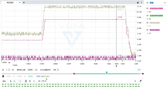
The voltage and current are more accurately acquired by the ADC using the CW32's unique 1.5V internal reference voltage.
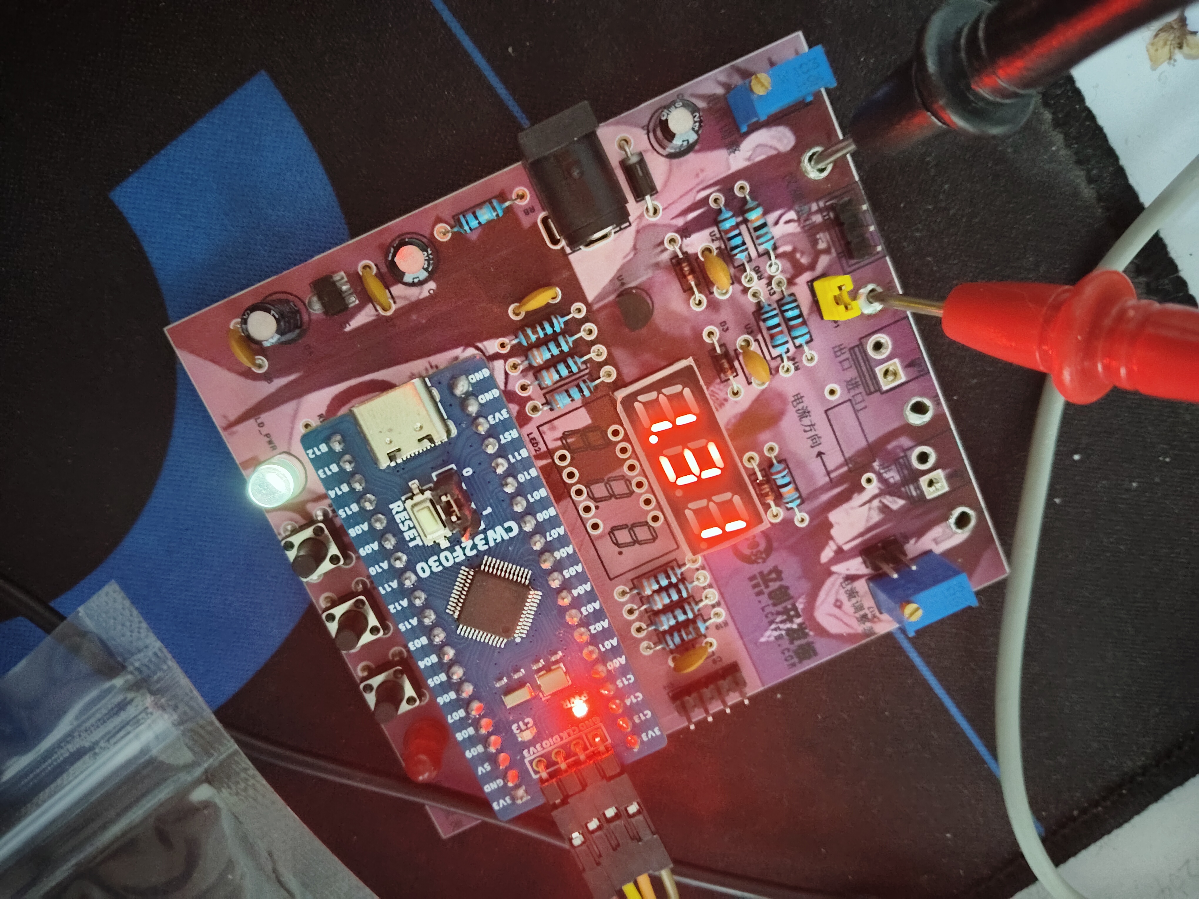
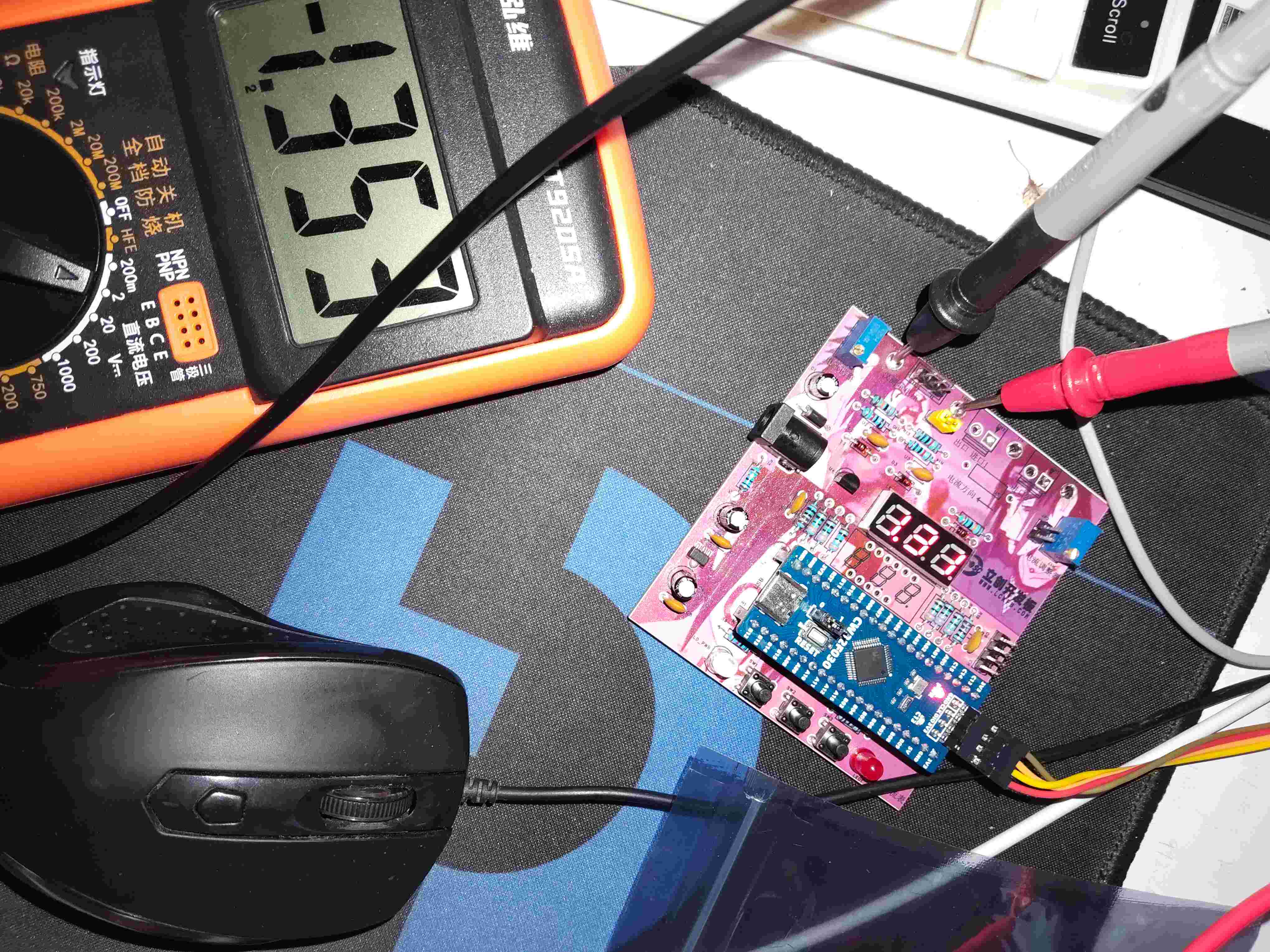
Physical Image
3.mp4
Open source code.zip
PDF_Voltage and Current Meters.zip
Altium_voltmeter_currentmeter.zip
PADS_Voltage and Current Meter.zip
BOM_Voltage and Current Meter.xlsx
92713
CW32-based digital voltmeter and ammeter — Jkun Mikey
LCSC Voltmeter and Ammeter Training Camp Closing Projects
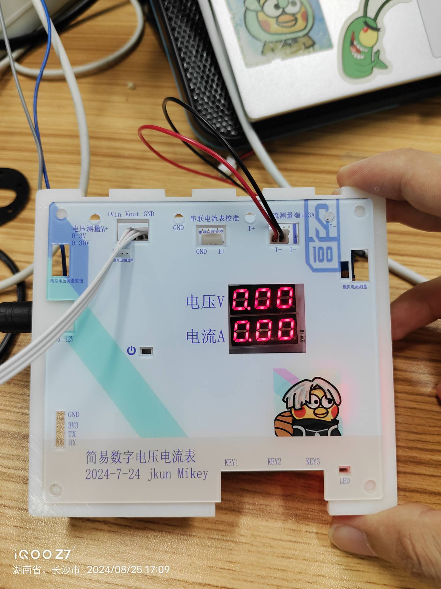
This was my first time making the casing and panel, so it wasn't perfect.
I. Project Introduction
(I) Project Background and Significance
Designing and building a digital voltmeter and ammeter is an excellent way to improve digital and analog electronics technology and microcontroller application capabilities. This project covers multiple aspects such as circuit design, signal acquisition and processing, and user interface development, making it very suitable for electronics beginners.
Through this JLCPCB training camp, I learned a lot by doing it myself—hardware, software, 3D modeling, panel design—and JLCPCB provided free coupons for all of these. It was almost zero cost; as long as you wanted to do it, there were many experts in the group helping to answer questions, creating a fantastic learning atmosphere. This is so much better than what schools teach!
LCPCB development boards truly don't aim to make money by selling boards; their mission is to cultivate Chinese engineers!
In short, I learned a lot through this, discovered my shortcomings, and enjoyed the process.
(II) Project Highlights
After completing the basic functions of the LCSC training camp digital voltmeter and ammeter, I added my own features. The most difficult part was the voltage and current calibration and measurement, both in hardware and software, but after doing it myself, it wasn't so difficult.
1. A small startup animation with two smiley faces:
2. To prevent accidental triggering, I changed KEY1 to a 2-second long press to enter the parameter setting interface. Double-clicking KEY2 confirms the modification of the corresponding calibration parameter value.
3. Voltage and current data can be sent to a host computer via serial port, or later treated as a module and sent to another microcontroller.
(III) The demonstration video
is finished, and I really learned something! _Bilibili_
https://www.bilibili.com/video/BV1BjWkevE8o/?vd_source=b3782bc780e6d1c9fbdb61b02c6df06b
II. Main Hardware Design
(I)
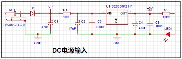
Selection of DC Power Supply LDO (Low Dropout Linear Regulator) This project uses an LDO as the power supply. Considering that most actual voltmeter products are used in industrial scenarios with 24V or 36V power supply, this project selected the SE8550K2 with a maximum input voltage of up to 40V as the power supply. The
SE8550K2 is a low dropout linear regulator with advantages such as stable output, low noise, and simple peripheral circuits. It is widely used in home appliances, communications, industrial control and other fields. Although the efficiency is relatively low, it is suitable for applications that require high-quality power output.
The main reason for not using a DC-DC step-down circuit to deal with the large dropout voltage in this project is to avoid introducing DC-DC ripple interference during the design process. The secondary reason is to reduce project costs.
(II) MCU Selection Analysis
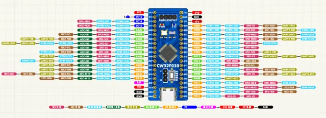
This project uses the LCSC CW32F030C8Tx development board (core board) as the main controller
. 1. Key Advantages of CW32 in this Project
: Wide operating temperature range: -40~105℃
Wide operating voltage range: 1.65V~5.5V (STM32 only supports 3.3V systems)
Strong anti-interference: HBM ESD 8KV All ESD reliability reaches the highest level of international standards (STM32 ESD 2KV)
Project Focus - Better ADC: 12-bit high-speed ADC can reach ±1.0LSB INL 11.3ENOB Multiple Vref reference voltages... ... (STM32 only supports VDD=Vref)
Stable and reliable eFLASH technology.
2. The main characteristics of the CW32's ADC are from the "CW32x030 User Manual"
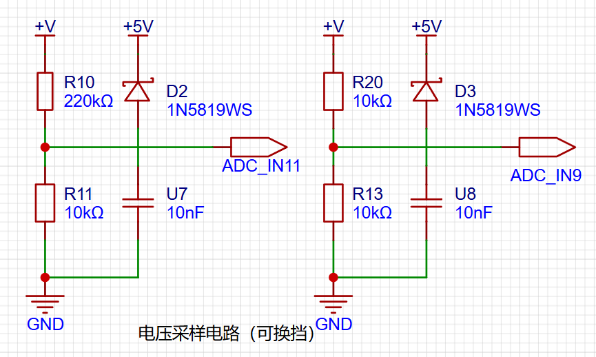
(Part 3) Voltage Sampling Circuit.
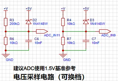
The voltage divider resistors in this project are designed to be 220K+10K, so the voltage division ratio is 22:1 (ADC_IN11).
1. Voltage Divider Resistor Selection
and Design: The maximum value of the measured voltage is 30V for safety reasons (the actual maximum can be displayed as 99.9V or 100V).
The ADC reference voltage is 1.5V in this project, and this reference voltage can be configured through the program.
To reduce the power consumption of the sampling circuit, the low-side resistor (R7) is usually chosen as 10K based on experience.
Then, the high-side resistance of the voltage divider resistor can be calculated using the above parameters.
The required voltage division ratio is calculated, i.e., the ADC reference voltage. The input voltage is designed; using known parameters, 1.5V/30V = 0.05 can be calculated.
The high-side resistance is calculated as the low-side resistance/voltage division ratio; using known parameters, 10K/0.05 = 200K can be calculated.
A standard resistor is selected: a resistor slightly higher than the calculated value of 200K is chosen. We usually choose E24 series resistors; therefore, in this project, 220K, which is greater than 200K and closest to the calculated value, is selected.
If, in actual use, the voltage to be measured is lower than 2/3 of the module's design voltage (66V), the voltage divider resistor can be replaced and the program modified to improve measurement accuracy. The following example illustrates this:
Assuming the measured voltage is no higher than 24V and other parameters remain unchanged,
calculations show 1.5V/24V = 0.0625, 10K/0.0625 = 160K. 160K is a standard E24 resistor and can be directly selected, or a higher value 180K can be chosen with some redundancy.
If, in actual use, the voltage to be measured is higher than the module's 99V design voltage, a different resistor can be selected. To achieve a wider voltage measurement range, consider replacing the voltage divider resistor or modifying the reference voltage. Here's a case study:
Assuming the measured voltage is 160V, we can choose to increase the voltage reference to expand the range.
Given that the voltage division ratio of the selected resistor is 0.0145, we can calculate 160V * 0.0145 = 2.32V using the formula. Therefore, we can choose a 2.5V voltage reference to increase the range (increasing the range will reduce accuracy).
Considering the potential fluctuations in the measured power supply, a 10nF filter capacitor is connected in parallel with the low-side voltage divider resistor to improve measurement stability.
2. Range Switching
In this project, an additional voltage sampling circuit was added. Therefore, we can discuss the significance of range switching for improving measurement accuracy. Multimeters often have multiple range settings for more accurate measurements. By adjusting different ranges, the optimal measurement accuracy of the measured point within the corresponding range can be obtained.
This project requires a combination of hardware and software to achieve this function. When we first use the ADC_IN11 channel mentioned earlier to measure voltages below 30V... If the measured voltage is within 0~3V, the ADC_IN9 channel is used for measurement. At this time, due to the reduced voltage division ratio, the measurement accuracy is greatly improved.
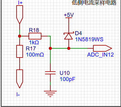
(IV) Current Sampling Circuit
This project uses a low-side current sampling circuit for current detection. The low-side of the sampling circuit shares a common ground with the development board's meter interface.
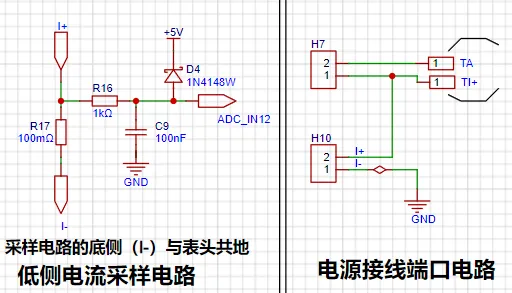
1. Design Analysis
The sampling current designed for this project is 3A, and the selected sampling resistor (R0) is 100mΩ. The following aspects need to be considered when selecting the sampling resistor: the maximum value of the pre-designed measurement current, the voltage difference caused
by the 3A current sensing resistor in this project , and it is generally not recommended to exceed 0.5V.
The power consumption of the current sensing resistor should be selected based on the appropriate package. Considering the power consumption (temperature) under high current conditions, a 1W metal wire-wound resistor was chosen for this project
. The voltage amplification factor of the current sensing resistor is 1 since no operational amplifier is used in this project.
The current sensing resistance value can then be calculated using the above parameters.
Since no amplifier circuit is used in this project, a larger sampling resistor is needed to obtain a higher measured voltage for measurement.
However, considering that a larger resistor would result in a larger voltage drop and higher power consumption, an unlimited selection of a larger resistor is not possible.
A 1W package resistor was chosen for this project, corresponding to a power rise of 1W
. Based on the above data, a 100mΩ current sensing resistor was selected. According to the formula, 3A * 100mΩ = 300mV, 900mW.
To handle different operating environments, especially high current scenarios, the R0 resistor can be replaced with constantan wire or a shunt. The appropriate alternative can be chosen based on the specific application scenario. For safety and educational purposes, this project will not discuss measurements exceeding 3A, but the principle remains the same.
(V) Digital Tube Display
This project uses digital tubes as the display unit.

Two 0.28-inch three-digit common-cathode digital tubes were used as the display device. Originally, an OLED or LCD was considered, but a mistake was made by forgetting to buy two different colored digital tubes.
The current-limiting resistors (R1~R6) for the digital tubes were configured to 300Ω. This resulted in good visibility for both red and blue digital tubes, with a soft and non-glaring brightness.
Strictly speaking, the current-limiting resistors should be added to the segments; adding them to the digits would affect the display effect. Adding them to the digits saves on resistors.
1. Digital Tube Power Supply
Current This project actually uses dynamic scanning to drive the digital tubes. Therefore, at any given time, only a maximum of 8 segments (or LEDs) of the digital tubes are lit, or in other words, only one digit is lit. According to the design, the required driving current is approximately 11mA (IO port high-level voltage 3.3V ÷ 300Ω).
At this point, it is important to ensure that the selected MCU has sufficient current-pull/sinking capability.
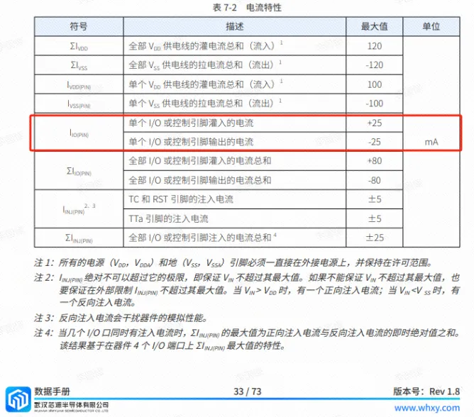
Analysis of the datasheet shows that CW32 meets the requirements.
voltammeter.rar
Gerber_Voltmeter & Ammeter PCB Diagram_2024-08-08.zip
PDF_Digital Voltage and Current Meter Based on CW32 - Jkun Mikey.zip
Altium-based CW32 digital voltage and current meter - Jkun Mikey.zip
PADS CW32-based Digital Voltage and Current Meter - Jkun Mikey.zip
92714
It's just a replica of a voltmeter and ammeter.
LCSC GeoStar CW32 Digital Voltage and Current Meter Expansion Board
I. Design Background
This project replicates the LCSC development board training camp project.
II. Hardware Design

1. LDO (Low Dropout Linear Regulator) Selection
This project uses an LDO as the power supply. Considering that most actual voltmeter products are used in industrial scenarios with 24V or 36V power supplies, this project selected the SE8550K2 with a maximum input voltage of up to 40V as the power supply. The main reason for not using a DC-DC step-down circuit to handle the large voltage drop is to avoid introducing DC-DC ripple interference during the design process; a secondary reason is to reduce project costs.
2. MCU Selection Analysis
The LCSC CW32F030C8Tx development board is used.
3. ADC Sampling Circuit
The design includes two sampling levels, with a maximum sampling voltage of 30V and an ADC reference voltage of 1.5V.
4. Current Sampling Circuit
This project uses a low-side current sampling circuit for current detection. When the low-side of the sampling circuit shares a common ground with the development board's meter interface
, please do not solder R0!
The sampling current designed for this project is 3A, and the selected sampling resistor (R0) is 100mΩ.
The selection of the sampling resistor mainly needs to consider the following aspects:
the maximum value of the pre-designed measurement current;
the voltage difference caused by the 3A current sensing resistor in this project;
and the power dissipation of the current sensing resistor, which is generally not recommended to exceed 0.5V. A suitable package should be selected based on this parameter. Considering the power dissipation (temperature) issue under high current, a 1W packaged metal wire-wound resistor was selected
. The voltage amplification factor across the current sensing resistor is also important. Since no operational amplifier is used to build the amplification circuit in this project, the factor is 1. The current
sensing resistor value can then be calculated using the above parameters.
Amplification circuits are used, so a larger sampling resistor is needed to obtain a higher measured voltage for measurement.
Considering that a larger resistor will result in a larger voltage drop and higher power consumption, a larger resistor cannot be selected indiscriminately.
This project uses a 1W package resistor, corresponding to a power rise of 1W.
Based on the above data, a 100mΩ current sensing resistor was selected for this project. According to the formula, 3A * 100mΩ = 300mV, 900mW can be calculated.
To cope with different usage environments, especially high current scenarios, the R0 resistor can be replaced with constantan wire or a shunt. The replacement can be selected according to the actual usage scenario. For safety and educational purposes, this project will not discuss the range beyond 3A in detail, but the principle is the same.
5. Digital Tube Display
This project uses a digital tube as the display unit.

This project uses two 0.28-inch three-digit common-cathode LED displays as the display device. Compared to a display screen, LED displays offer better visibility in complex environments. The brightness of the LED displays can be increased by using smaller current-limiting resistors, depending on the specific needs of the application environment. Furthermore, LED displays have better mechanical properties and are not as easily damaged by external forces as display screens. They are widely used in industrial applications where stability and reliability are crucial. From a development board learning perspective, this makes it easier to learn electronic measurement principles and related development in a targeted manner.
In this project, actual testing showed that the current-limiting resistors (R1~R6) for the LED displays were configured to 300Ω. The corresponding brightness for both red and blue LED displays was good, and the brightness was soft and not glaring.
Strictly speaking, the current-limiting resistors should be added to the segments; adding them to the digits would affect the display effect. Our actual design places them in the digits to save a few resistors, but the impact on the display is not significant. Therefore, we add them to the digits for convenience.
The
driving
principle of an LED display mainly involves controlling the switching state of each segment to display numbers, letters, or symbols. The following is a detailed explanation of the driving principle:
Basic Structure of a Digital Tube:
A digital tube typically consists of seven or eight LED segments (eight segments in this project). Each segment represents a part of the digital tube and can display numbers 0-9, letters AF, etc.
Digital tubes come in two types: common cathode and common anode. The difference lies in whether the common terminal COM (the end connecting all LEDs) is connected to the negative or positive terminal of the power supply.
Driving Methods:
Segment Selection: The desired number or character is displayed by controlling the on/off state of each segment of the digital tube. Each segment corresponds to a control signal; when the control signal is on, the segment lights up, and vice versa. (a, b, c, d, e, f, g, dp)
Bit Selection: The digital tube to be displayed is selected by controlling the bit lines of the digital tube. Bit line control sets the bit line of the digital tube to be displayed to a high level, and the bit lines of other digital tubes to a low level. By continuously switching the state of the bit lines, the display switching between multiple digital tubes can be achieved.
Driving Circuit:
The driving circuit for a digital tube can be implemented using hardware circuits, such as integrated circuits like digital signal processors (DSPs), microcontrollers (MCUs), or shift registers, to generate control signals suitable for the LEDs.
These control signals can be in the form of pulse width modulation (PWM) signals, serial data signals, etc. By controlling the frequency, width, and amplitude of these signals, the brightness of the digital tube can be controlled, thereby displaying the desired numbers or letters.
Software Control:
In addition to hardware driving circuits, the driving of digital tubes can also be implemented through software control. By programming to generate control signals suitable for the digital tubes, more flexible and complex display effects can be achieved, such as scrolling or alternating display of numbers.
Driving Common Cathode and Common Anode Digital Tubes:
For common cathode digital tubes, the common cathode pin is connected to the negative terminal of the power supply, and the control pin is connected to the output pin of the control chip. When a certain number needs to be displayed, the control chip outputs the corresponding encoded signal to the control pin, causing the corresponding LED segment to light up.
For common anode digital tubes, the working principle is similar to that of common cathode digital tubes, except that the common anode pin is connected to the positive terminal of the power supply, and the control pin is connected to the output pin of the control chip.
Encoded Display:
In order for the digital tube to display the corresponding numbers or characters, the segment data port must output the corresponding character encoding. For example, to display the number "0", the character code for a common anode seven-segment display is 11000000B (i.e., C0H), while the character code for a common cathode seven-segment display is 00111111B (i.e., 3FH). The specific code depends on the actual seven-segment display.
Dynamic and Static Display:
Seven-segment displays can use either static or dynamic display methods. In static display, each of the eight segments of a seven-segment display is connected to an 8-bit I/O port address. As long as the I/O port outputs a segment code, the corresponding character is displayed and remains unchanged. Dynamic display, on the other hand, lights up each segment of the seven-segment display one by one, achieving simultaneous visual display through rapid switching.
In summary, the driving principle of seven-segment displays is to control the switching state of each segment of the seven-segment display to display numbers, letters, or symbols, and to achieve display switching between multiple seven-segment displays through segment selection and digit selection. Simultaneously, the driving of the seven-segment display can be implemented through hardware circuits or software control, and common cathode or common anode seven-segment displays can be selected as needed.
This project actually uses dynamic scanning display to drive the seven-segment display.
Let's estimate the current required for the seven-segment display .
This project actually uses dynamic scanning to drive the digital tube, so at any given time, only a maximum of 8 segments of the digital tube (or LEDs) can be lit, or in other words, only one segment can be lit. According to the design, the required driving current is approximately 11mA, which is the high-level voltage of the IO port 3.3V ÷ 300Ω.
At this point, it is important to ensure that the selected MCU has sufficient current sinking/pull-up capability.
[image.png
image.png]
Analysis of the datasheet shows that the CW32 is fine. (Some chips are not suitable.)
6. LED Indicator
This project additionally designed a power indicator and an IO working indicator.
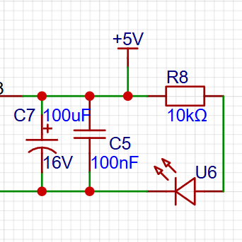

Since the chip's I/O often has a greater current sinking capability than a current pulling capability, LED1 is designed to be active low (lit).
To reduce the current consumption of the LED, some LED brightness is sacrificed, the component parameter types are reduced, and the current-limiting resistor for the LED is selected as 10K.
7. Button Circuit Design

There are various design methods for the button control circuit. Thanks to the fact that the CW32's I/O port can be configured with pull-up and pull-down resistors internally, the button control circuit on the outside of the chip does not need to be configured. One end of the button is connected to the MCU's I/O, and the other end is grounded. When the button is pressed, the I/O is pulled low.
8. TL431 Circuit Design for Voltage Measurement and Calibration
This project adds an extra TL431 circuit to provide a 2.5V reference voltage, which can be used to provide an external voltage reference for the chip to calibrate the AD converter. From a product design perspective, due to the inherent ADC performance advantages of the CW32, this circuit is not necessary. This circuit is designed on the development board to learn the relevant application principles.
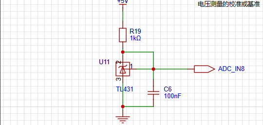
The TL431 is a relatively "old" device, very classic, and widely used; it is still found in many electronic products.
Many beginners may be encountering this device for the first time, so we will briefly explain the principles of this product to help everyone better apply the TL431.
TI defines it as a precision programmable reference. On the first page of the references, we can focus on several key characteristics.
Precision: Precision indicates that its output voltage is very accurate. I used a TL431 with ±0.5% accuracy, and the measured voltage on the board at room temperature was 2.495V. Compared to common Zener diodes, the accuracy is vastly different. In application circuit diagrams, the TL431 is internally represented by a Zener diode symbol.
Adjustable output voltage: The adjustable output voltage is between Vref and 36V. In our project, we use the output Vref voltage, which is approximately 2.5V. Therefore, we use 2.5V in the description, which is approximately equal to the actual voltage.
Sinking current capability: This refers to how much current the output voltage pin can provide, which is greatly affected by the resistance value (R13) in the application circuit. It should not be less than 1mA. If there is no need for sinking current, do not design the current to be too high, as this will cause unnecessary power consumption.
94ccb099b348960b413b790b3fb58803.mp4
PDF_Just a replica of a voltmeter and ammeter.zip
Altium is simply a replica of a voltage and current meter. (zip file)
PADS is simply a replica of a voltage and current meter. (zip file)
BOM_ is just a replica of a voltage and current meter.xlsx
92715
Voltage and current meter based on CW32F030
A voltage and current meter was developed using the CW32F030 microcontroller. It displays voltage and current values in real time, supports data calibration, and can be applied to various electrical measurement scenarios.
This design utilizes a CW32F030-based voltmeter and ammeter to measure voltage and current, and provides voltage calibration. The hardware design employs the JLCPCB EDA Professional Edition.
Background:
ADCs (Analog-to-Digital Converters) are indispensable components in electronic systems, converting continuous analog signals into digital signals, enabling digital processing and analysis. ADCs play a crucial role in signal conversion, measurement and data acquisition, control system input, and communication and signal processing. Their widespread application promotes the intelligent and precise control of electronic equipment across various industries, and is a key factor driving modern technological progress. Digital voltmeters and ammeters combine ADC technology with circuit measurement principles, accurately converting analog voltage and current signals into digital displays for intuitive reading and analysis by electronic engineers. This device not only improves the accuracy and efficiency of circuit measurements but also helps engineers better understand circuit behavior, serving as a powerful tool for electronic design and troubleshooting, and significantly supporting the work of electronic engineers. In product applications, digital voltmeters ensure the accuracy and safety of circuit design, while also providing strong support for product quality control and subsequent maintenance.
The voltage divider resistors in this project are designed to be 220K+10K, therefore the voltage division ratio is 22:1 (ADC_IN11).
The voltage divider resistor selection
is based on the maximum measured voltage; for safety reasons, this project uses 30V (the actual maximum display value can be 99.9V or 100V).
The ADC reference voltage in this project is 1.5V, which can be configured through the program.
To reduce power consumption in the sampling circuit, the low-side resistor (R7) is usually selected as 10K based on experience.
The high-side resistance of the voltage divider resistors can then be calculated using the above parameters.
The required voltage division ratio is calculated as follows: ADC reference voltage: Design input voltage, calculated using known parameters as 1.5V/30V=0.05.
The high-side resistance is calculated as: Low-side resistance/voltage division ratio, calculated using known parameters as 10K/0.05=200K.
A standard resistor is selected: A resistor slightly higher than the calculated value is chosen; the calculated value is 200K. We usually choose E24 series resistors, therefore in this project, 220K is selected, which is greater than 200K and closest to the calculated value.
If, in actual use, the voltage to be measured is lower than 2/3 of the module's design voltage (66V), the voltage divider resistor can be replaced and the program modified to improve measurement accuracy. The following example illustrates this:
Assuming the measured voltage is no higher than 24V and other parameters remain unchanged,
calculations show 1.5V/24V = 0.0625, 10K/0.0625 = 160K. 160K is a standard E24 resistor and can be directly selected, or a higher value 180K can be chosen with some redundancy.
If, in actual use, the voltage to be measured is higher than the module's 99V design voltage, a different resistor can be selected. To achieve a wider voltage measurement range, you can choose to replace the voltage divider resistor or modify the reference voltage. Here's a case study:
Assuming the measured voltage is 160V, we can choose to increase the voltage reference to expand the range.
Given that the voltage division ratio of the selected resistor is 0.0145, we can calculate 160V * 0.0145 = 2.32V using the formula. Therefore, we can choose a 2.5V voltage reference to increase the range (increasing the range will reduce accuracy).
Considering the potential fluctuations in the measured power supply, a 10nF filter capacitor is connected in parallel with the low-side voltage divider resistor to improve measurement stability. This
is my first time doing hardware design, so the PCB layout is not very efficient and it's not very convenient to use.
Photos of the finished product are below;

firmware and a demonstration video are attached below.
Voltmeter and Ammeter.mp4
Project.hex
CW32x030_UserManual_CN_V2.4.pdf
PDF_Voltmeter and Ammeter Based on CW32F030.zip
Altium_Voltage and Current Meter Based on CW32F030.zip
PADS_Voltage and Current Meter Based on CW32F030.zip
BOM_Voltage and Current Meter Based on CW32F030.xlsx
92716
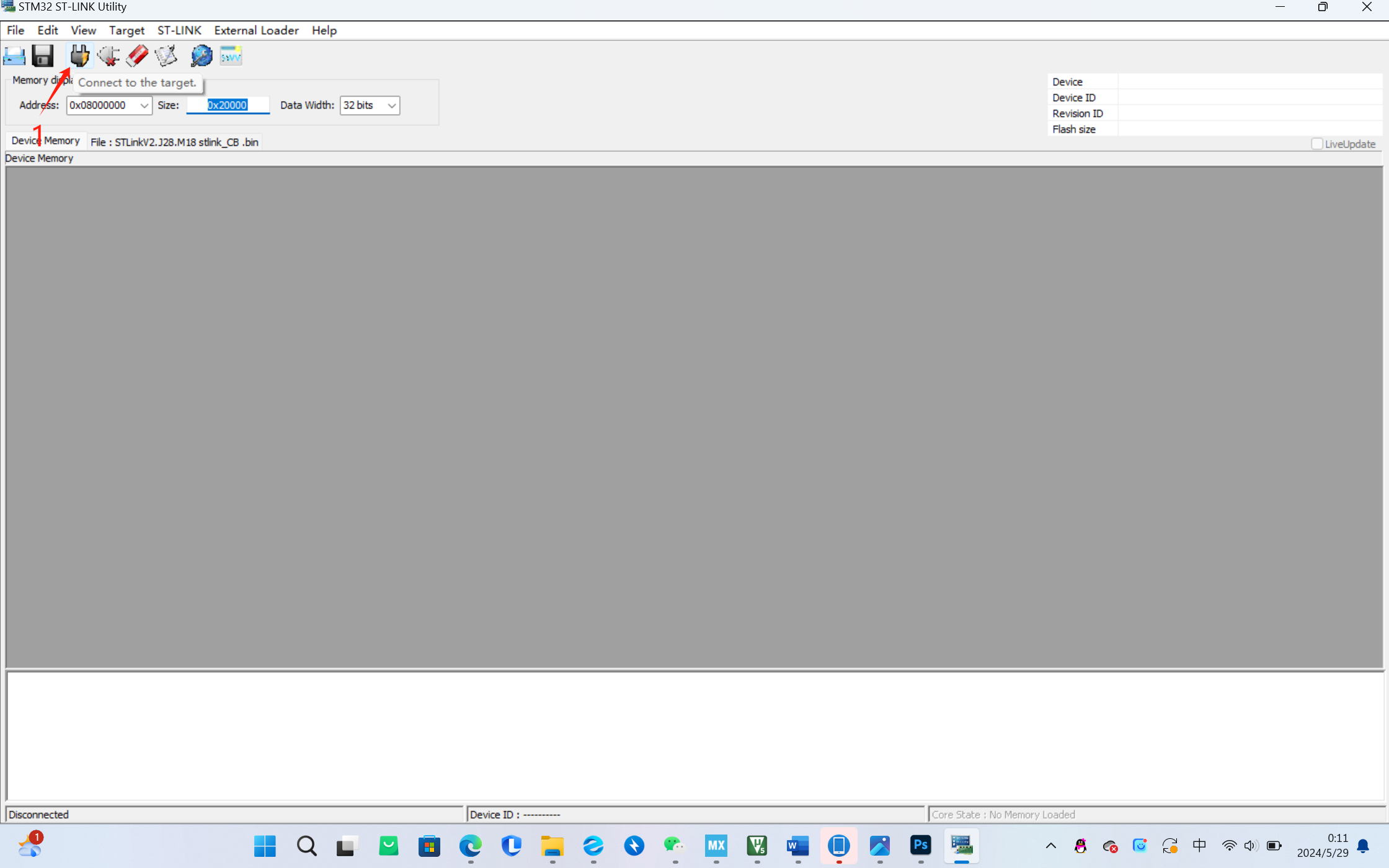
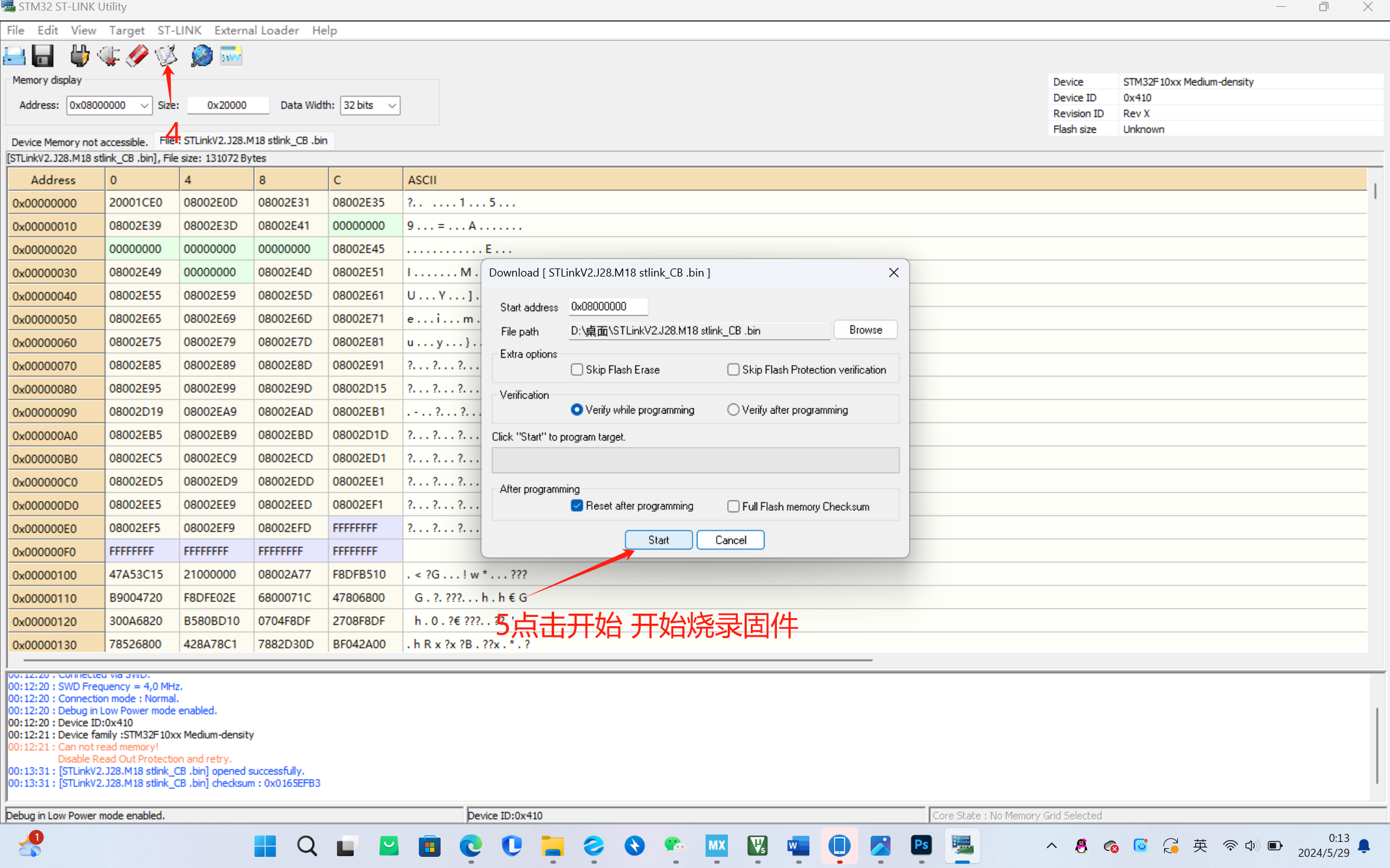
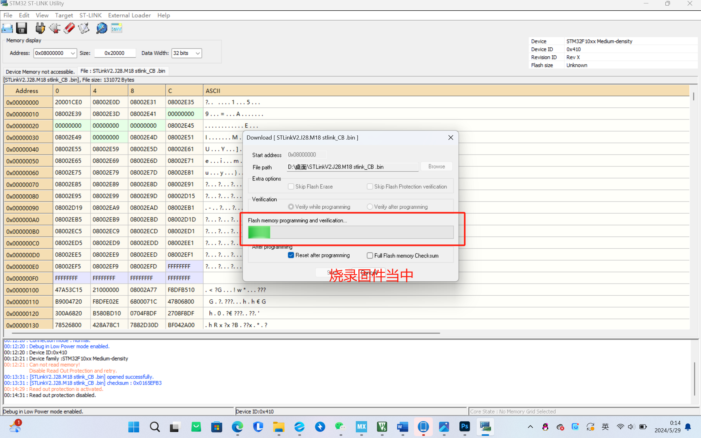
ST-LINK V2 Downloader with Isolation
This project aims to design and optimize an isolated STLINK programmer for firmware flashing and debugging of embedded systems in an isolated environment. Efficiency is achieved by improving performance and stability, reducing size and power consumption, optimizing circuit design and software implementation, and providing a user-friendly interface and documentation.
Note! The main board uses an STM32F103CBT6; a C8T6 cannot be used as a substitute.
Online Simulation: Enables online simulation of the device, facilitating debugging and testing.
Serial Communication: Provides stable serial communication for data interaction and communication with the device.
High Efficiency and Reliability: Through optimized design and implementation, it offers high efficiency and reliable performance.
It meets the needs of online simulation, serial communication, and firmware download in embedded system development, providing developers with convenient and reliable tools. Through this device, users can easily perform device debugging, data interaction, and firmware updates, improving development efficiency and accuracy.
During device debugging, sudden board malfunctions will not burn out the computer.

During downloading or online simulation, the two LEDs above will flash alternately.
STLinkV2.J28.M18 stlink_CB .bin
8e45be3e5b8cc264fe754cc7dd839a57.mp4
7e9aab0e3131610a4a0293741295bf6a.mp4
PDF_ST-LINKV2 Downloader with Isolation.zip
Altium_ST-LINKV2 Downloader with Isolation.zip
PADS_ST-LINKV2 Downloader with Isolation.zip
BOM_ST-LINKV2 Downloader with Isolation.xlsx
92717
electronic


 京公网安备 11010802033920号

 AME8501CEFTDD23


