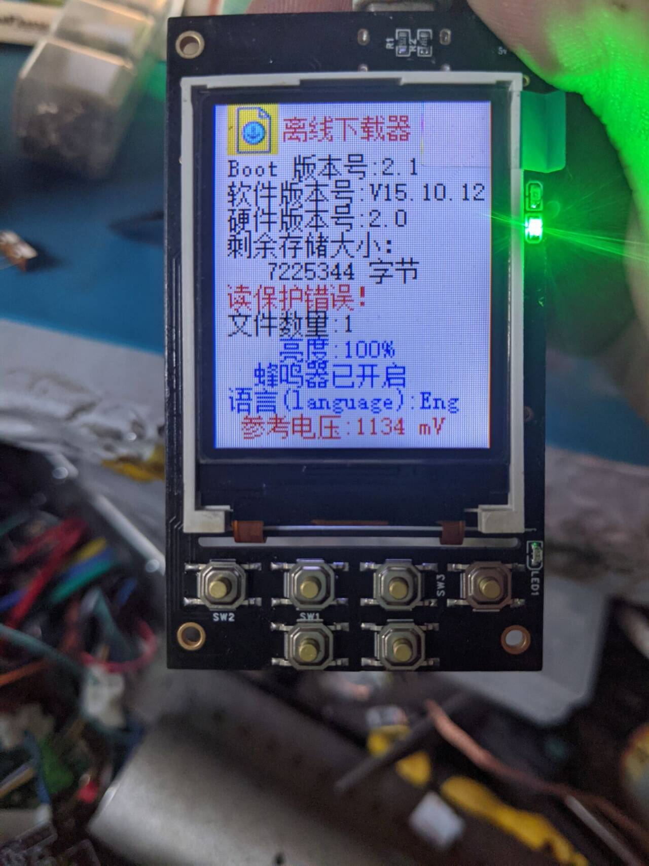
STM32 offline downloader. Both are the same; one is an optimized version, changed to a 4-layer board, some components removed, and the charging IC replaced with a TP4057
. All tests show normal operation. The main controller is an STM32F103RET6, and the screen is an ST7735. The total cost is estimated to be around 50 RMB. Screen link: https://m.tb.cn/h.gbvIYAtu7MRMbDj?tk=mQ1OWsNXQ1I
For questions, join group 320628128.
OfflineDownloader.hex
QQ Video 20240513124417.mp4
HID_OFD-V4.3.2-2021.02.22.exe
PDF Offline Downloader.zip
Altium Offline Downloader.zip
PADS_Offline Downloader.zip
BOM_Offline Downloader.xlsx
94740
Based on the [LCSC Taishanpai Development Board] small mobile phone project
This project replicates the "Fat Girl Mobile Phone" training camp from Taishan School. In the process, you can learn how to set up a Linux virtual machine environment, commonly used Linux commands, SDK compilation, device trees, and MIPI screen debugging.
1. Project Introduction
This project introduces the replication process of the Taishanpai development board project "Fat Girl Phone," providing assistance to those who also want to replicate it.
2. Project Materials
The project materials include official documents and video tutorials provided by LCSC development board. The materials detail the environment setup and device tree parameter modification process, and provide code patches and assembly tutorials in Chapter 7, the comprehensive mobile phone project.
Documentation Tutorials: "Fat Girl Phone" Practical Project Materials
Video Tutorials: Collection · "Taishanpai Training Camp" LCSC · Taishanpai RK3566 Linux Development Board
3. Schematic Diagram Explanation
The adapter board's function is to connect a 3.1-inch screen to the Taishanpai and provide backlight voltage to the screen. The schematic diagram includes: MIPI interface, touch interface, backlight circuit, and audio interface.
Detailed schematic diagram explanation Refer to the document: Circuit Principle Analysis
1. MIPI Interface
Since the MIPI interface type and wiring sequence of the 3.1-inch screen and the Taishanpai development board are inconsistent, an adapter is required. 1. **Adapter Board:** Connects the 3.1-inch screen to the Taishanpai's MIPI interface. The type and wiring sequence of the adapter board's interface are determined by the screen and the Taishanpai's MIPI interface.
2. **Touch Interface:** The adapter board
connects the screen's touch interface to the Taishanpai's touch interface.
3. **Backlight Circuit:** The
backlight circuit mainly consists of a backlight selection circuit, a backlight drive circuit, and a backlight adjustment circuit. Note that components marked NC in the schematic do not need to be soldered.
4. **Audio Interface:**
The audio interface consists of a speaker and microphone jack.
4. Replication Process
Computer Configuration:
Laptop Model: Acer Swift 3 RTX3050
CPU: AMD Ryzen 7 5800U with Radeon Graphics 1.90 GHz
Memory: 16GB
Hard Drive: Reserved 500GB SSD
4.1 Environment Setup
Reference Documents: Environment Setup
Step 1: Install Ubuntu virtual machine using VirtualBox, refer to 【VirtualBox】Ubuntu Compilation Environment Setup
Step 2: Set up Samba, refer to Samba Setup
4.2 SDK Compilation
Reference Documents: Android 11 SDK
Step 1: Download SDK
Step 2: Complete verification, decompression, code synchronization, and compilation environment installation
Step 3: Full compilation of Android 11
During the compilation process in step 3, the following two errors occurred
: ninja failed with: exit status 137
ninja failed with: exit status 1
Refer to the following materials to solve the errors:
Reference 1: Common Problem Solutions for Compiling Android 4/5/6/7/8/9/10/11 System Source Code on Ubuntu 18.04/20.04 Virtual Machine
Reference 2: ninja failed with: exit status The steps to resolve issue 137
are as follows:
1. In VirtualBox, set the installed virtual machine's memory to 12GB and the processor to 8 cores
. 2. Set JavacHeapSize to 6GB, following the solution in Reference 1.
3. Set swap to 32GB, following the solution in Reference 2.
4. Recompile using `make j-4`. The compilation should take approximately 6 hours. The steps are:
`cd u-boot && ./make.sh rk3566 && cd ../kernel && make clean && make distclean && make ARCH=arm64 tspi_defconfig rk356x_evb.config android-11.config && make ARCH=arm64 tspi-rk3566-user-v10.img -j4 && cd .. && source build/envsetup.sh && lunch rk3566_tspi-userdebug && make installclean -j4 && make -j4 && ./mkimage.sh`
4.3 Applying the code patch and completing kernel compilation:
Step 1: Download the complete patch, 1.4.5 complete code patch (3.1-inch screen touch driver patch.zip).
Step 2: After decompression, find the following files and replace the compiled files using Samba
: "tspi-rk3566-dsi-v10.dtsi" and "tspi-rk3566-user-v10.dts" in the rockchip folder
; "Makefile" and "my_touch" in the touchscreen folder
; "Makefile" and "my_gp7101_bl" in the backlight folder.
Note that line 54 of the "Makefile" in the provided touchscreen folder needs to be modified.
The original file should be:
obj-$(CONFIG_TOUCHSCREEN_GSL3673) += gsl3673-ts.o
obj-y += my_touch/
Modify it to:
obj-$(CONFIG_TOUCHSCREEN_GSL3673) += Step
3
: Compile the kernel separately, refer to Compiling the Kernel Separately with Android 11 SDK (only suitable for versions with eMMC).
4.4 PCB fabrication, purchasing components, soldering, 3D printing the shell, assembly.
Reference: VII. Comprehensive Mobile Phone Project (3. Free PCB Prototyping, 4. PCB Soldering Practice, IV. Shell)
4.5 Flashing
Step 1: Download Rockchip Development Tool v2.92, Chapter 7. [LCSC·Taishanpai RK3566] Development Tool
Step 2: Import the configuration "Android_All_Config.cfg" into the Rockchip Development Tool, refer to Compiling Android 11.
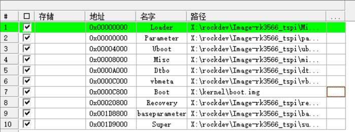
Step 3: Select all and choose the path, except for boot.The image file is located in the kernel folder, while the others are located in the rockdevImage-rk3566_tspi folder.
Step 4: Burn the program.
Demo.mp4
PDF_Based on the [LCSC Taishanpai Development Board] Small Mobile Phone Project.zip
Altium-based small mobile phone project using the LCSC Taishanpai development board. (zip file)
PADS_Based on the [LCSC Taishanpai Development Board] Small Mobile Phone Project.zip
BOM_Based on the [LCSC Taishanpai Development Board] Small Mobile Phone Project.xlsx
94741
[Based on Taishanpai - Fat Girl's Little Phone] 7394266A
Based on the Taishanpai development board and expansion board launched by JLCPCB, along with a series of live broadcasts, recorded videos, and document tutorials, we guide electronics enthusiasts and open source supporters to quickly get started with Linux, understand the Linux project development process, work on projects together, and have fun together.
I. Project Introduction
Following this training camp was my first step into Linux. Through this project, I learned the basic Linux framework, development environment setup, commonly used Linux commands, simple driver debugging, device tree concepts, and I also learned to draw PCB diagrams and debug driver code, gaining a preliminary framework for debugging a product.
II. Project Materials
Please refer to the official documentation:
【胖妞手机】泰山派RK3566 Development Board - JLCPCB EDA Open Source Hardware Platform (oshwhub.com)
https://www.bilibili.com/video/BV1gF4m1u7n3/?spm_id_from=333.999.0.0
III. Project Showcase
https://t.bilibili.com/930539449669910578?share_source=pc_native

WeChat_20240513134321.mp4
PDF_【Based on Taishanpai - Chubby Girl's Little Phone】7394266A.zip
Altium_【Based on Taishanpai - Chubby Girl's Little Phone】7394266A.zip
PADS_【Based on Taishanpai - Chubby Girl's Little Phone】7394266A.zip
BOM_【Based on Taishanpai - Chubby Girl's Little Phone】7394266A.xlsx
94742
Example Project - Quick Start
Quick Start Demo Project
Quick Start Demo Project
PDF_Sample Project_Quickstart.zip
Altium Sample Projects Quickstart.zip
PADS Sample Projects Quick Start.zip
BOM_Sample Project_Quickstart.xlsx
94744
air001 serial motor driver v0.2
Serial port control of 4-channel motor drivers (with speed measurement)
The onboard MCU and 4-channel driver chip RZ7899 enable driving four DC motors and measuring their speed via serial port commands.
It specifically solves the problems of cumbersome 4WD smart car driver development, excessive I/O port usage, and high MCU resource consumption. Only one serial port is needed to replace the original 8-channel PWM and 4-channel input capture (speed measurement).
Detailed specifications: http://120.78.94.15/
Direct purchase: https://item.taobao.com/item.htm?ft=t&id=794770186843&skuId=5426543657912&spm=a21dvs.23580594.0.0.1d293d0dPLQAUq
PDF_air001 Serial Motor Driver v0.2.zip
Altium_air001 serial motor driver v0.2.zip
PADS_air001 serial motor driver v0.2.zip
BOM_air001 Serial Motor Driver v0.2.xlsx
94745
Exhibition board sand table
Life needs to discover creativity and beauty.
This is the first open-source project I've created at LCSC, and it serves as a starting point.
This project involves custom exhibition panels, available in various sizes (from sand table and roll-up banners to A4 paper), with options for single-color and multi-color programmable control light strips, etc.; AI voice functionality can also be added on top of these panels; and the project can be adapted for practical use.
Top view.png
Half top view.png
Rear view.png
LED_GD32_SCH.pdf
test.mp4
firmware.hex
PDF_Exhibition Board Sand Table.zip
Altium_Exhibition Board Sand Table.zip
PADS_Exhibition Board Sand Table.zip
BOM_Exhibition Board Sand Table.xlsx
94746
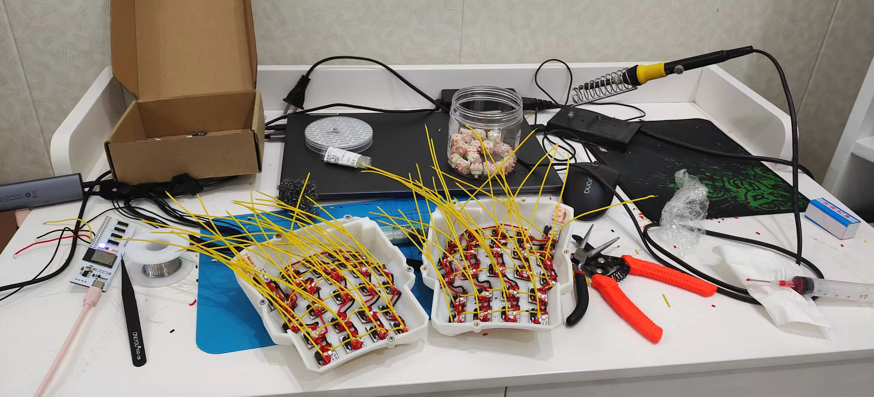
Dactyl-HelloWord Ergonomic Keyboard ESP32
This is a Dactyl ergonomic keyboard using the HelloWord firmware, with an ESP32S3 controller. The author was mainly responsible for copying and pasting.
I. Introduction
My old keyboard was worn smooth from use, and I was planning to buy a new one. Then a colleague suggested I look into custom keyboards.
I was shocked by the price – four figures! Forget it!
Since I don't have the money, I'll have to make one myself.
II. Acknowledgements & References
https://oshwhub.com/pengzhihui/b11afae464c54a3e8d0f77e1f92dc7b7
【Hanwen】HelloWord-Keyboard
https://oshwhub.com/dimsmary/dactyl-helloworld
Dactyl-HelloWord Ergonomic Keyboard
https://www.thingiverse.com/thing:3403277
dactyl Case
III. Design Summary
I stumbled upon Zhihui's HelloWord-Keyboard and was immediately impressed. I wanted one, but the sheer amount of components and the price were a huge barrier. I was outside that barrier, while A-Key was inside.
Then I looked for a low-end option, and luckily, the name "Dactyl-HelloWord Ergonomic Keyboard" was a popular choice. While any keyword like that would be a drain on your wallet, this project offered good value. After trying it out online, I found that typing without a numeric keypad was too cumbersome and didn't suit my needs, so I decided to DIY (copy and paste).
In the design, I used an ESP32 as the main controller, since I only knew how to use it. I eliminated the FPC cable and used flying wires to reduce costs and soldering requirements. The PCB design for the switches was the same.
Both left and right sides used the same PCB, with software controlling which controller was the main controller. Communication between the left and right sides used ESP-NOW. Later, I discovered that the ESP's power consumption was too high in the Bluetooth wireless version, so I didn't add a built-in battery; battery life depends on the size of your power bank.
Printing cost 120 yuan, the two main controllers cost about 50 yuan, the switches were cheap (0.6 yuan each), and the keycaps cost 21 yuan, for a total cost of 300 yuan. Actually, the left and right connections could have been designed according to the "Dactyl-HelloWord Ergonomic Keyboard" design, which would have saved even more money.
Gitee: https://gitee.com/lyj0329l/keyboard-dactyl
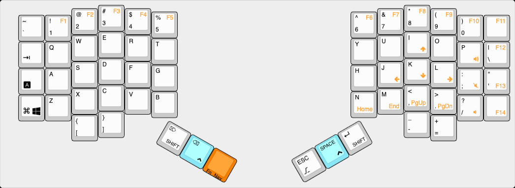
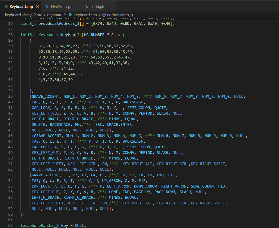
IV. Key mapping is defined
in two layers: a basic layer and a function key and navigation key layer.
V. Physical demonstration

PDF_Dactyl-HelloWord Ergonomic Keyboard ESP32.zip
Altium_Dactyl-HelloWord Ergonomic Keyboard ESP32.zip
PADS_Dactyl-HelloWord Ergonomic Keyboard ESP32.zip
BOM_Dactyl-HelloWord Ergonomic Keyboard ESP32.xlsx
94747
Temperature alarm
The most basic 51 microcontroller (STC89C52RC) is equipped with a DS18B20 and a buzzer (either passive or passive) and uses an LCD1602 display.
Features
include the ability to use modular DS18B20 and DS18B20 transistors
to support high-precision temperature detection (four decimal places).
The alarm device uses a buzzer, which is inexpensive and practical.
Important notes:
Pay attention to chip soldering and component orientation
. Passive
buzzers have
a lower volume, while active buzzers have a higher volume. The source
code is included in the compressed package.
The set temperature is 15 degrees Celsius
and can be changed in the main function of the source code.
If using a DS18B20
transistor instead of a DS18B20 module, a 10K pull-up resistor must be connected to the P37 port of the chip.
Temperature alarm.zip
PDF_Temperature Alarm.zip
Altium_TemperatureAlarm.zip
PADS_Temperature Alarm.zip
BOM_Temperature Alarm.xlsx
94748
electronic


 京公网安备 11010802033920号

 19S10N-40ML5


