I. Design Background
An ADC (Analog-to-Digital Converter) is an indispensable key component in electronic systems. It converts continuous analog signals into digital signals, enabling digital processing and analysis. ADCs play a crucial role in signal conversion, measurement and data acquisition, control system input, and communication and signal processing. Their widespread application promotes the intelligent and precise control of electronic equipment across various industries, and is one of the key factors driving modern technological progress. Digital voltmeters and ammeters combine ADC technology with circuit measurement principles, accurately converting analog voltage and current signals into digital displays for easy reading and analysis by electronic engineers. This device not only improves the accuracy and efficiency of circuit measurements but also helps engineers better understand circuit behavior, serving as a powerful assistant in electronic design and troubleshooting, and playing a vital supporting role in the work of electronic engineers. In product applications, digital voltmeters ensure the accuracy and safety of circuit design, while also providing strong support for product quality control and subsequent maintenance. Learning to design and build a digital voltmeter and ammeter
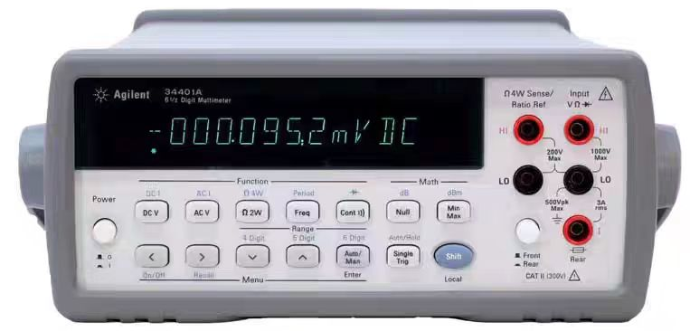
using a benchtop digital multimeter (Agilent 34401A)
is highly beneficial for improving one's professional skills. This digital voltmeter and ammeter project covers multiple aspects, including microcontroller circuit design and implementation, signal acquisition and processing circuit design, user interface development and optimization, and product appearance design. It integrates knowledge from multiple fields such as electronics, microcontroller programming, circuit design, and industrial design. Considering the learning pace and knowledge absorption capacity of beginners, we have specially launched this introductory-level digital voltmeter and ammeter project, which is very suitable for beginners in electronics and those who want to learn more about microcontroller applications. This project has the following highlights:
it adopts a core board plus expansion board design concept and uses plug-in components, making learning simpler and exploration more in-depth;
the core board uses the domestic Wuhan Xinyuan Semiconductor CW32 as the main controller, while also being compatible with other similar development boards; however, the CW32 has advantages.
The project is highly comprehensive and practical, and after completion, it can be used as a desktop instrument;
the project has abundant learning materials, including circuit design tutorials, PCB design, code programming learning, and training for engineers' debugging skills.
II. Hardware Design
1. Voltage Sampling Circuit
The voltage divider resistor in this project is 220K+10K, so the voltage division ratio is 22:1 (ADC_IN11).
The voltage divider resistor is
selected to measure the maximum voltage. For safety reasons, this project uses 30V (the actual maximum can be displayed as 99.9V or 100V).
The ADC reference voltage is 1.5V in this project, and this reference voltage can be configured through the program.
To reduce the power consumption of the sampling circuit, the low-side resistor (R7) is usually chosen as 10K based on experience.
Then, the high-side resistance of the voltage divider resistor can be calculated using the above parameters.
The required voltage division ratio is calculated, i.e., the ADC reference voltage. The input voltage is designed; using known parameters, 1.5V/30V = 0.05 can be calculated.
The high-side resistance is calculated as the low-side resistance/voltage division ratio; using known parameters, 10K/0.05 = 200K can be calculated.
A standard resistor is selected: a resistor slightly higher than the calculated value of 200K is chosen. We usually choose E24 series resistors; therefore, in this project, 220K, which is greater than 200K and closest to the calculated value, is selected.
If, in actual use, the voltage to be measured is lower than 2/3 of the module's design voltage (66V), the voltage divider resistor can be replaced and the program modified to improve measurement accuracy. The following example illustrates this:
Assuming the measured voltage is no higher than 24V and other parameters remain unchanged,
calculations show 1.5V/24V = 0.0625, 10K/0.0625 = 160K. 160K is a standard E24 resistor and can be directly selected, or a higher value 180K can be chosen with some redundancy.
If, in actual use, the voltage to be measured is higher than the module's 99V design voltage, a different resistor can be selected. To achieve a wider voltage measurement range, one can choose to replace the voltage divider resistor or modify the reference voltage. The following example illustrates this:
Assuming the measured voltage is 160V, the solution is to increase the voltage reference to expand the range.
Given that the voltage division ratio of the selected resistor is 0.0145, we can calculate 160V * 0.0145 = 2.32V using the formula. Therefore, we can choose a 2.5V voltage reference to expand the range (increasing the range will reduce accuracy).
Considering the potential fluctuations in the measured power supply, a 10nF filter capacitor is connected in parallel with the low-side voltage divider resistor to improve measurement stability.
Range switching:
In this project, an additional voltage sampling circuit was added. Therefore, we can discuss the significance of range switching for improving measurement accuracy. Multimeters often have multiple range settings for more accurate measurements. By adjusting different ranges, the optimal measurement accuracy of the measured point within the corresponding range can be obtained.
This project requires a combination of hardware and software to achieve this function. When we first use the ADC_IN11 channel mentioned earlier to measure voltages below 30V... If the measured voltage is within 0~3V, then the ADC_IN9 channel is used for measurement. In this case, the measurement accuracy is greatly improved due to the reduced voltage division ratio. There are many ways to implement gear shifting, and the development board design provides more design possibilities.


 京公网安备 11010802033920号

 MB90F343E


