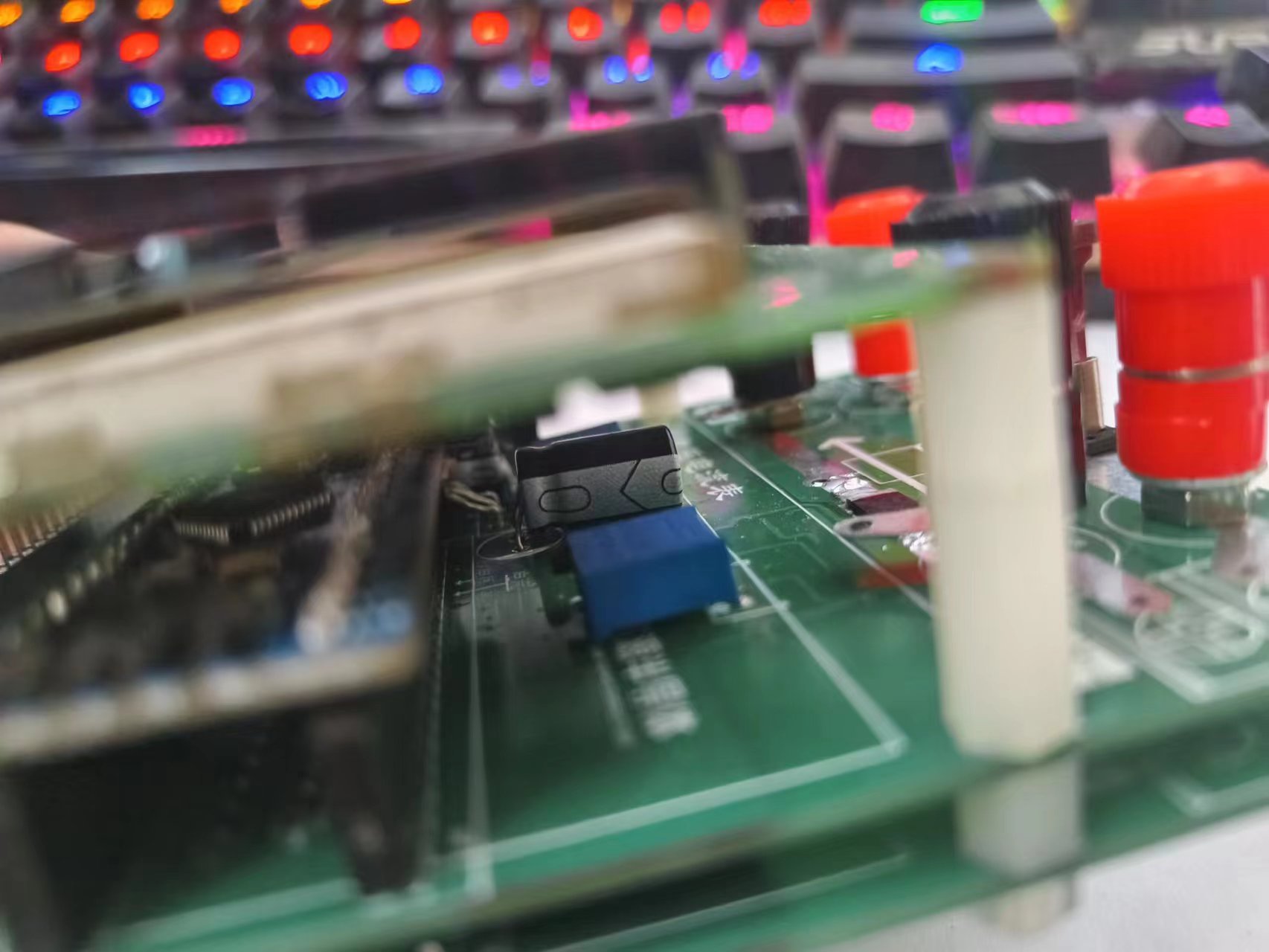
This is a brief description
of a voltage and current meter using the LCSC CW32F030 main controller, with a built-in Bluetooth module. All remaining I/O pins are brought out, allowing for the addition of an electronic load module or a constant voltage/constant current module in the subsequent stages. The schematic design details a 50V voltage divider , measuring in two ranges: 30V and 50V. The divider resistors are 0.1% resistors, calculated as 300kΩ and 15kΩ . R11 and R13 are not soldered; R12 and R14 are shorted to form a current-following circuit. The current section has a maximum current of 8A, measured in 5A and 8A ranges. The amplification factor is 30x . Currently calibrated at 30V and 5A (no power supply greater than 30V 5A is available). Calibration is performed every 1V for voltage and every 0.5A for current. Software Description Code Block: /** 1. Calibration signal originates from Bluetooth ## Clears all calibration information #v1 Calibrates voltage, channel 1. v represents voltage, 1 represents channel #i1 Current, i represents current, 1 represents channel 1 #$ Calculates K and saves multiple sets of k to flash 2. Storage of calibration information Address 0-1 indicates whether calibration information exists, 0xaa indicates calibration information exists, others indicate no calibration information. Occupies 2 bytes, read/write using 16 bits Address 2-5 Stores whether voltage channel n has been calibrated, each channel occupies 1 bit, totaling 4 bytes, read/write using 16 bits Address 6-7 Stores whether current channel n has been calibrated, totaling 2 bytes, read/write using 16 bits Address 8-207 Calibration data for 50 voltages, 50*4 = 200 bytes Address 208-291 Calibration data for 16 currents, 16*4 = 84 */ /* Calculate K value */ float ComputeK(uint32_t x1,uint32_t x2,uint16_t delta_y) { float k=0; k = (float)(delta_y)/(float)(x2-x1); return k; } /*Voltage calculation K*/ void ComputeKv(uint32_t *read_results,FloatInUnion *kv) { for(uint8_t i=0;i<50; i++) { (*(kv+i)).kf = (ComputeK(*(read_results+i),*(read_results+i+1),1000)); } } /*Current calculation K*/ void ComputeKi(uint32_t *read_results,FloatInUnion *ki) { for(uint8_t i=0;i<16; i++) { (*(ki+i)).kf= (ComputeK(*(read_results+i),*(read_results+i+1),500)); } } calibrate Bluetooth protocol 1. The calibration signal comes from Bluetooth ## to clear all calibration information #v1 is the calibration voltage 1 channel v represents voltage 1 represents channel #i1 is the current i represents current 1 represents channel #$ to calculate K and save multiple sets of k to flash /*calibrate*/ int8_t calibration(unsigned char *buff) { // used to decode information from Bluetooth char str[2]; str[0] = *(buff+2); str[1] = *(buff+3); int channel = atoi(str); printf("channel is %d ",channel); // used to store the verification value FloatInUnion kv[50]; FloatInUnion ki[16]; if(*(buff+1) == 'v') { read_voltage_results[channel] = get_voltage_val() ; } else if(*(buff+1) == 'i') { read_current_results[channel] = get_current_val() ; } else if(*(buff+1) == '#') { flash_erase(); } else if(*(buff+1) == '$')


{
uint16_t IsCal = 0;
flash_read(0,&IsCal,1);
if(IsCal == 0xaa) // Calibrated
{
}
else // Not calibrated
{
IsCal = 0xaa;
ComputeKi(read_current_results,ki); // Calculate current K 16-channel
flash_write_32(208,(uint32_t *)ki,16); // Save current K to FLASH
ComputeKv(read_voltage_results,kv); // Calculate voltage K 50-channel
flash_write_32(8,(uint32_t *)kv,50); // Save voltage K to FLASH
flash_write(0,&IsCal,1); // Update to calibrated
}
}
else
{
printf("Calibration Error!! Please check!!
");
return 1;
}
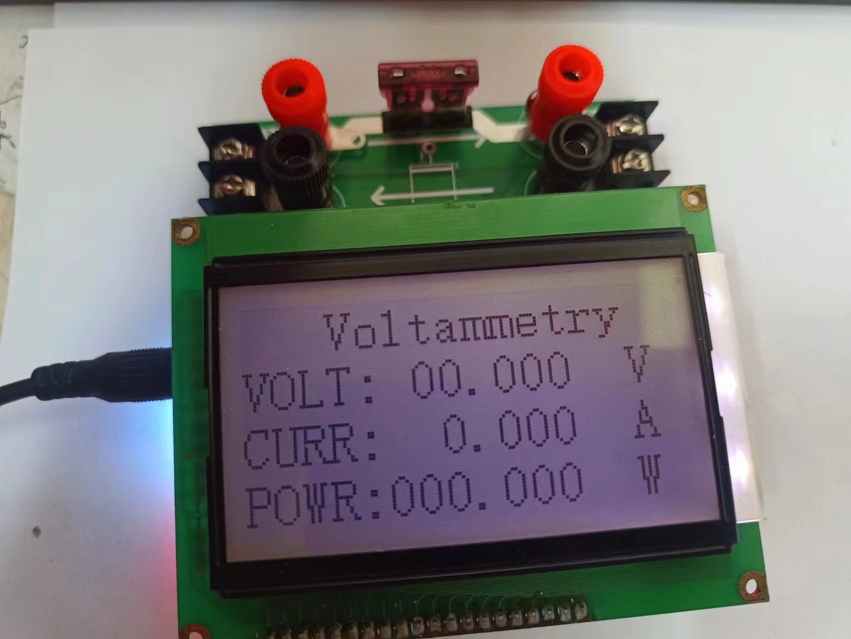
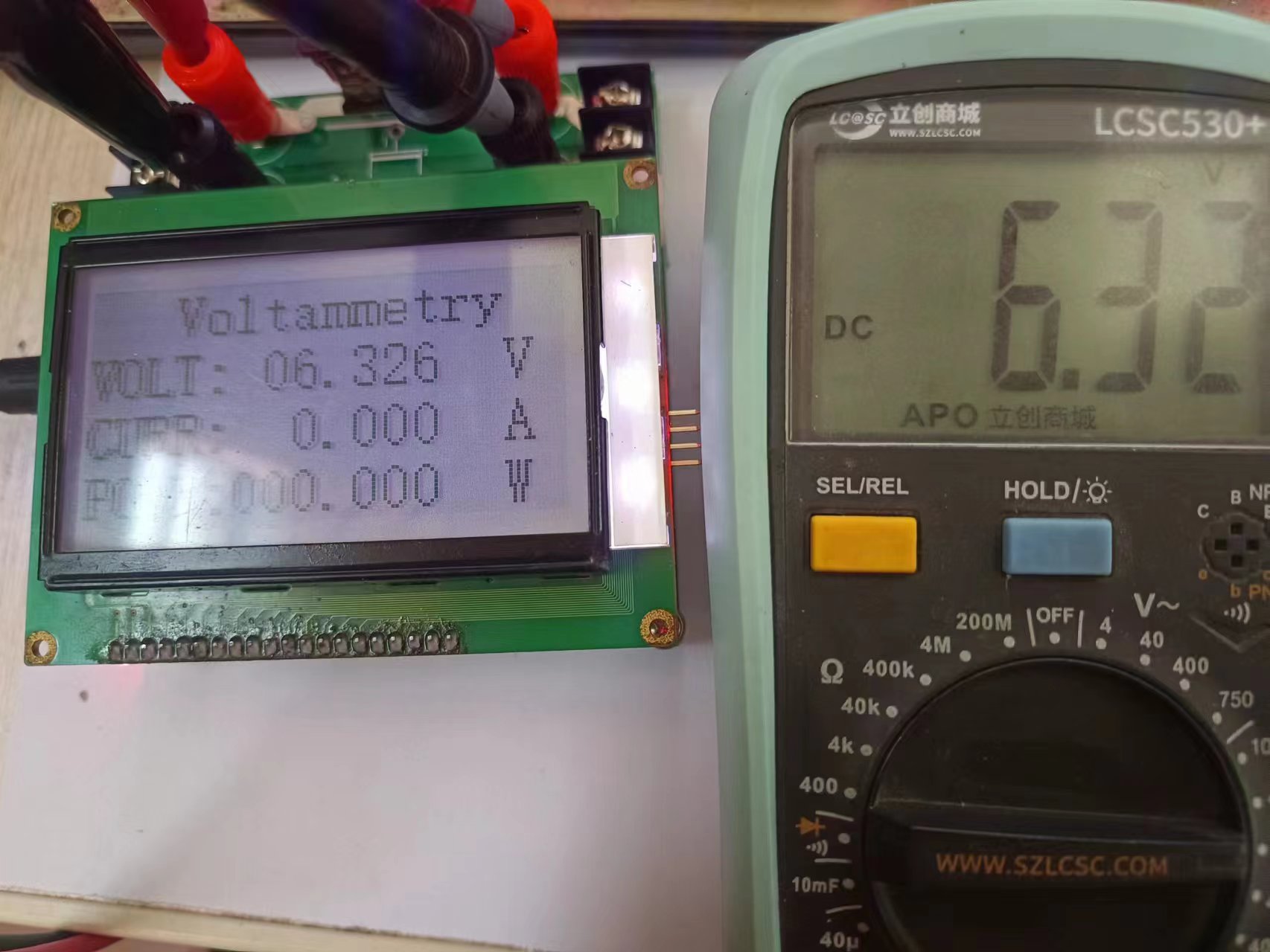
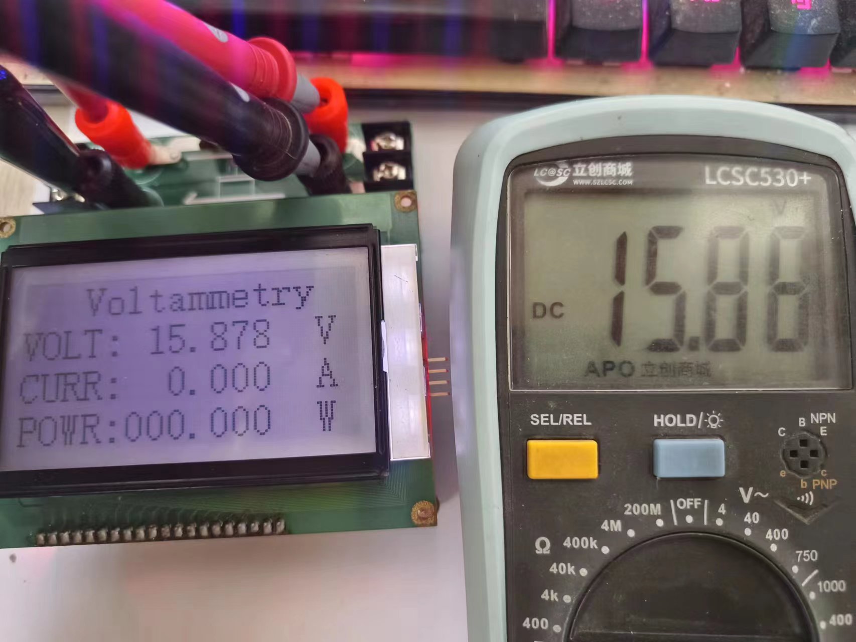
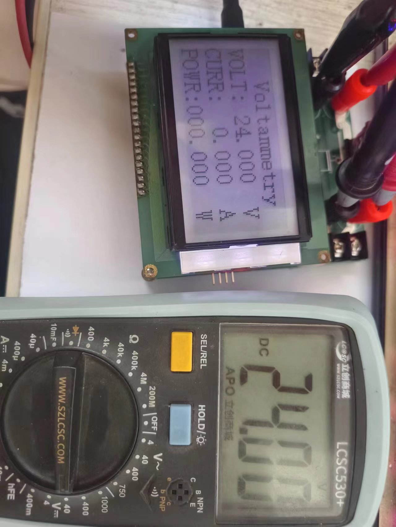
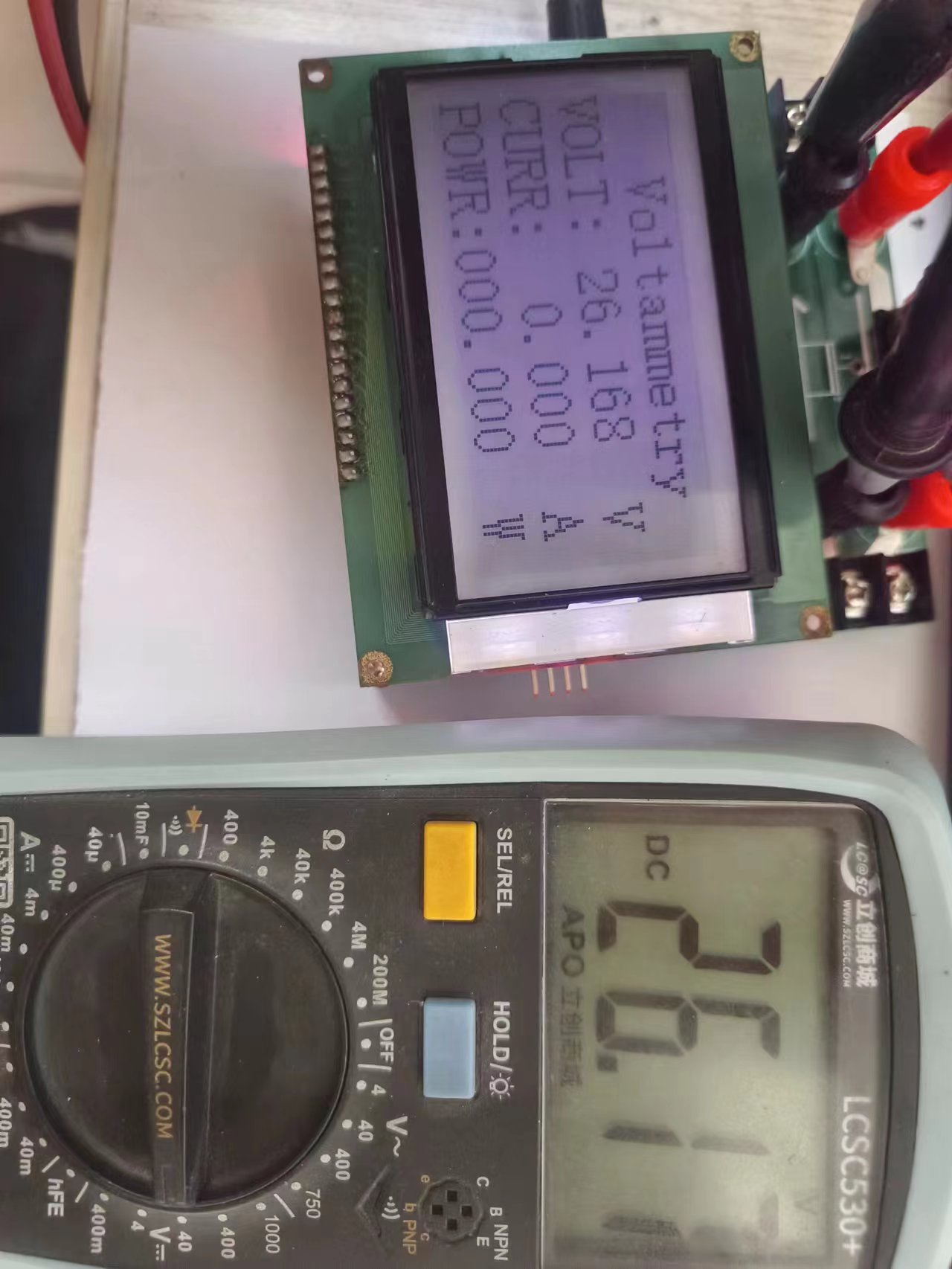
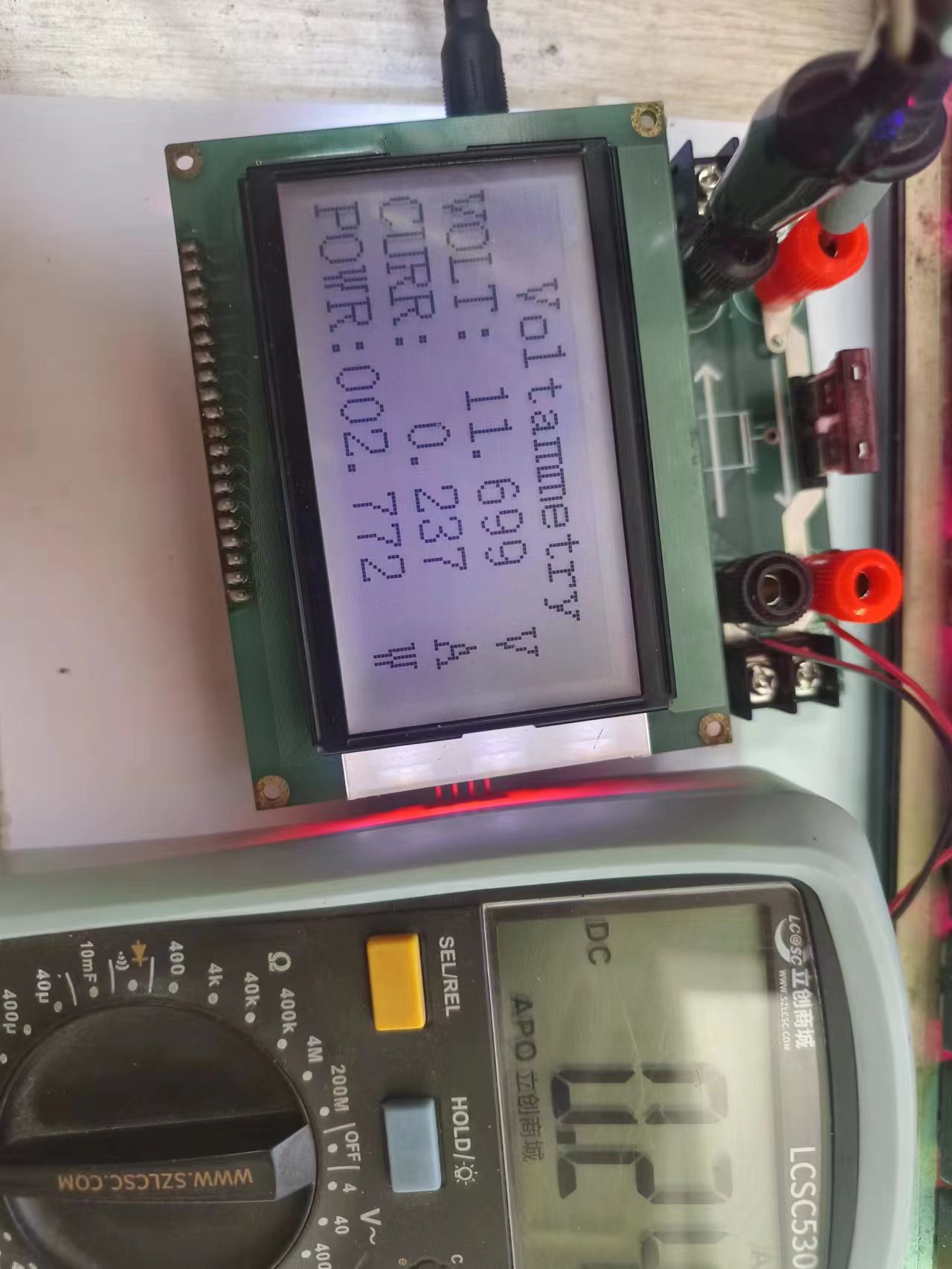
return 0; The physical demonstration shows that voltage measurement is generally okay, but small current testing (with significant fluctuations) is required.
Other notes: During debugging, adjust the potentiometer first to bring the op-amp output to 0. Voltage measurement is good, but current measurement fluctuates significantly, possibly due to incomplete calibration. The electronic load is still a semi-finished product; I only used it for a rough calibration and will calibrate it further. Important note regarding replication: Contact me first if you need a replication; it will greatly help with a successful replication.


 京公网安备 11010802033920号

 C1808Z100K5XAH


