UART: uses two serial ports to interact with the Bluetooth module and voice module respectively;
Bluetooth connects to a mobile phone, allowing users to check temperature and humidity from the comfort of their bed;
the voice module is used to alert users when temperature and humidity reach alarm values
. Additionally, this project uses battery power, and
semi-finished products such as battery charging and discharging circuits are shown.
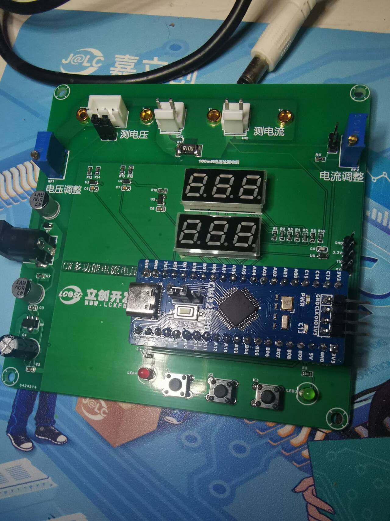
Based on the CW32F030C8T6 simple voltmeter and ammeter, a very useful digital voltmeter and ammeter.
I'd always heard about the high accuracy of the CW32
's ADC, but I'd never had the chance to use it. I even missed the training camp organized by the CW32 ecosystem community. Thanks to LCSC EDA and the CW32 ecosystem community for providing the 1 RMB development board and other coupons, and for organizing this training camp, they taught us how to build a voltage and current meter step-by-step.
On the hardware side
, this voltage and current meter offers two voltage division ratios for measuring voltage,
provides four sockets for comparative testing and calibration with multimeters and other measuring tools,
uses a 100 milliohm resistor for voltage sampling, calculates and measures current,
increases current routing, and supports high current input.
On the software side
, it supports switching ADC sampling pins to change ranges,
switching reference voltages to change accuracy and calibration, and
calibration to adjust measured values .
During the construction process
, I followed the teacher's schematics step-by-step, learning a lot of key technical knowledge and PCB design skills
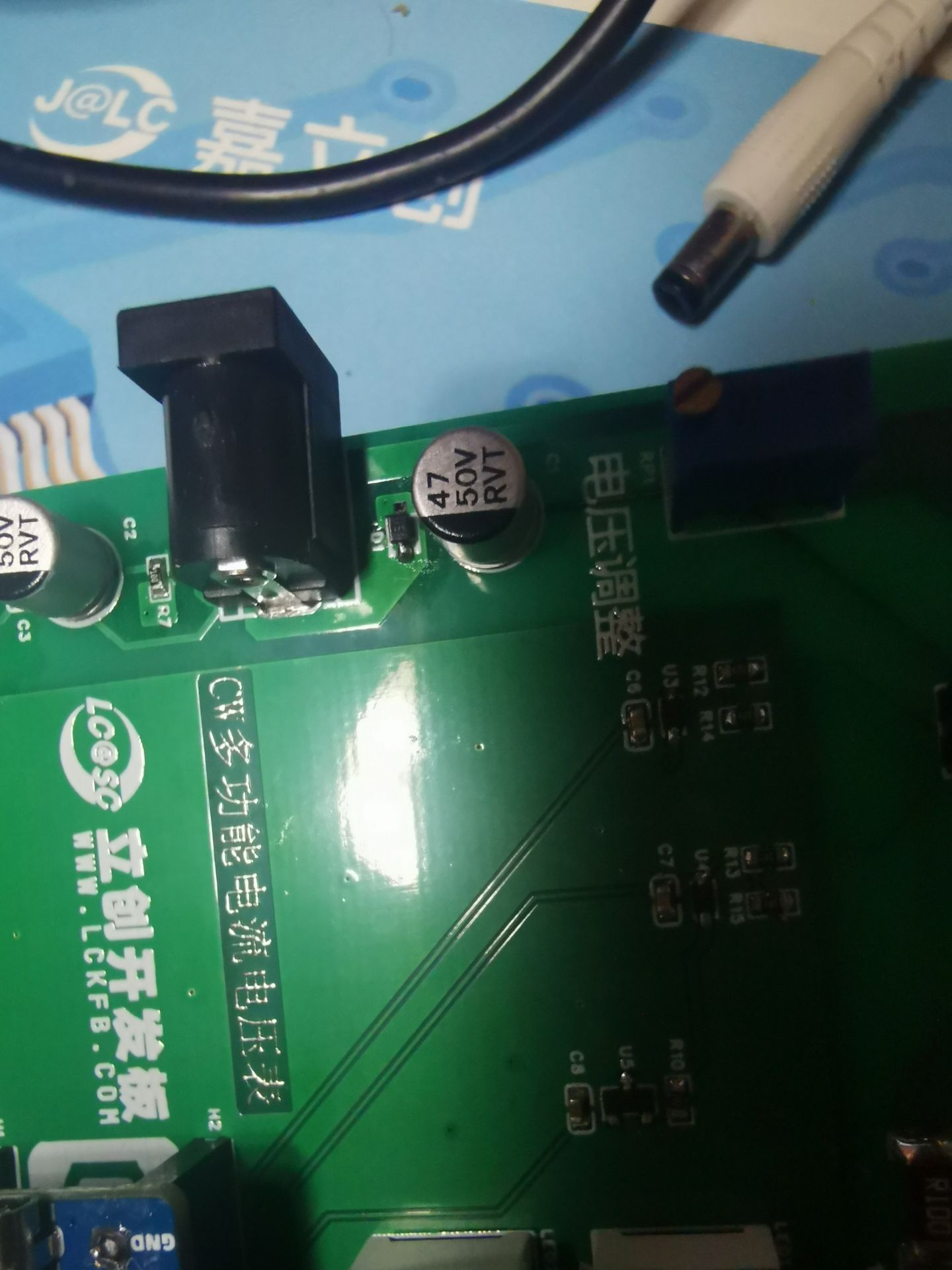
, but I still encountered many pitfalls, including accidentally drawing the board incorrectly. After soldering, the power indicator light didn't turn on when plugged into a DC power supply, but it did work when plugged into a USB port. After much research and testing with a multimeter, I finally found the problem. I had drawn the diode at the DC power input position backwards, preventing power from flowing. I removed the diode, reversed its orientation, and the problem was fixed.
The schematic has also been corrected.

Below is a picture of the actual circuit .

QQ Video 20240814114558.mp4
Digital voltmeter and ammeter.hex
PDF_CW32 Simple Voltage and Current Meter.zip
Altium_CW32 Simple Voltage and Current Meter.zip
PADS_CW32 Simple Voltage and Current Meter.zip
BOM_CW32 Simple Voltage and Current Meter.xlsx
93136
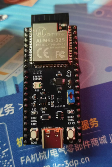
AI_M61-32S Core Board
The core board was designed using the Ai-Thinker AI_M61-32S module, with all pins brought out for easy functional testing.
I previously worked with the Anxinco
AI-M61-32S kit development board for a while, but found some minor flaws. So I designed my own, with pins fully compatible with the AI-M61-32S kit. I added a USB port and used an RS2227 to switch between USB and UART serial ports. It also includes an automatic download circuit.
All resistors, capacitors, and LEDs are 0402 diodes. It has one onboard common-cathode RGB LED, and a jumper cap allows selection between USB and serial ports. A custom-coded 50x50 QR code is included.
The BOM is inaccurate; please refer to the schematic .
(Two attached images are included.)

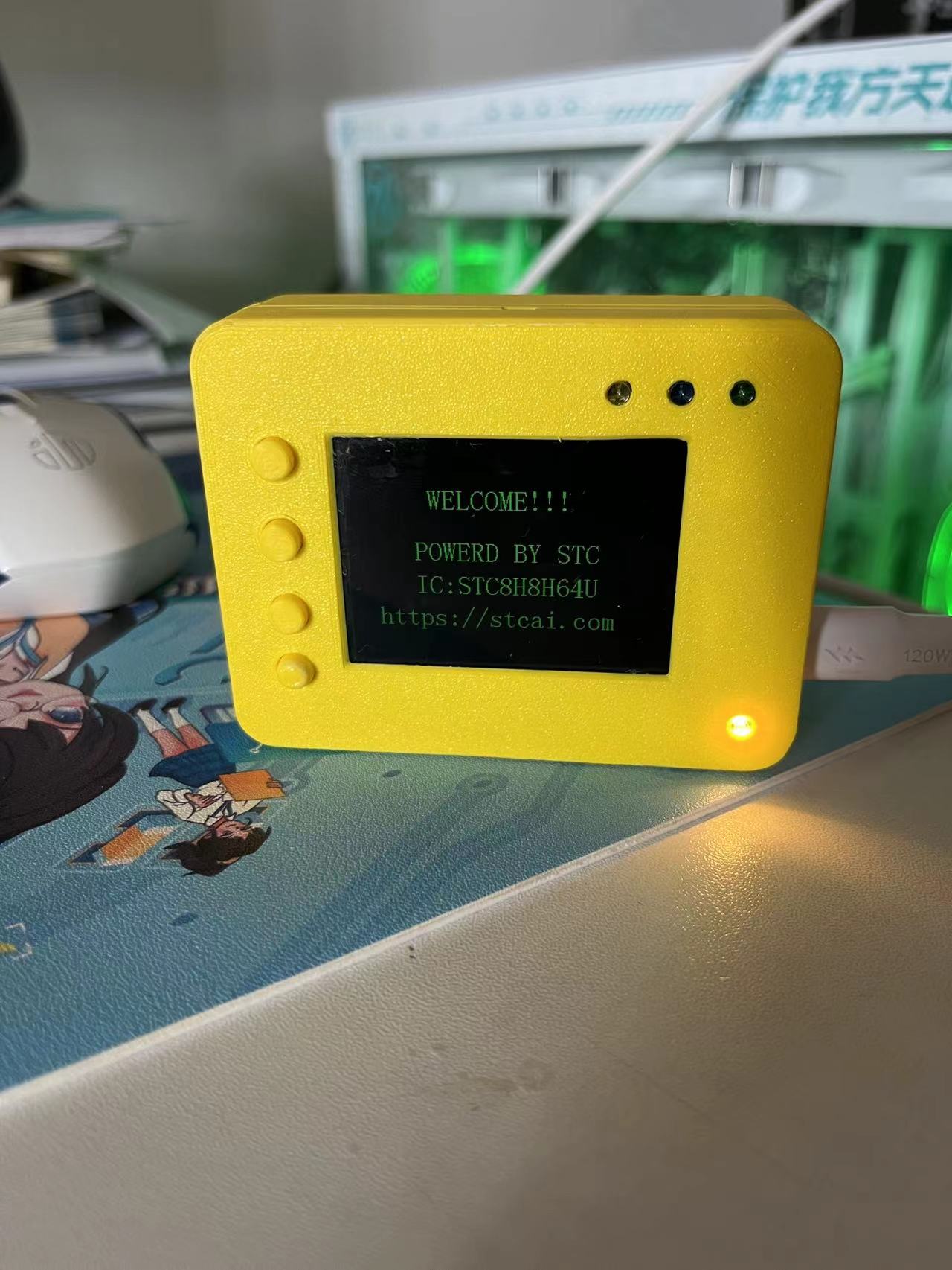
Let's turn on the LED:
input.mp4
PDF_AI_M61-32S Core Board.zip
Altium_AI_M61-32S core board.zip
PADS_AI_M61-32S core board.zip
BOM_AI_M61-32S Core Board.xlsx
93137
electronic


 京公网安备 11010802033920号

 2MA129-330MF


