Introduction
This project is based on the open-source project "P150C Pro-D CNC Electronic Load Battery Capacity Tester" by @CNWANS. For
details of the original open-source project, please refer to: P150C Pro-D CNC Electronic Load Battery Capacity Tester Firmware
Burning Reference: P150C Pro CNC Electronic Load Firmware Download
Inherited from the original open-source project Requirements: Everyone is free to play with this project, but you must not commercialize this project (small-scale production and sales are not a big deal). This project is partially owned by cnwans.com.
The bill of materials generated by the system may have problems. Please check carefully!
Partial Modification Instructions
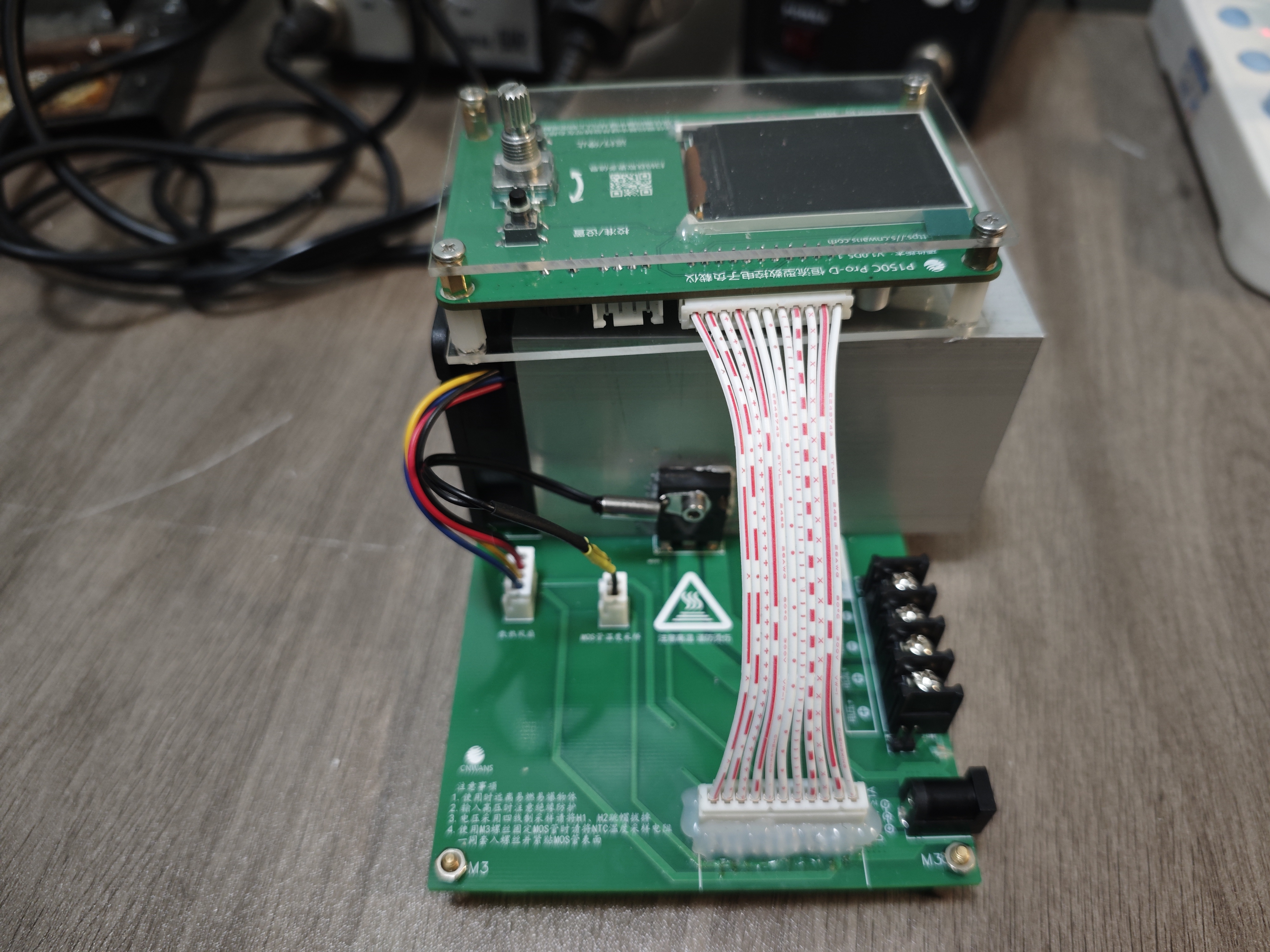
The PCB is divided into two parts: a power board and a control board. The division scheme is based on @Old Li who repairs computers.
(1) Power Board Layout Modification
1. Change the heat dissipation method: Originally, it was CPU fan down-pressure heat dissipation -> Now it is hollow heat pipe surface heat dissipation
2. NTC sampling resistor: Originally, it was a surface-mount resistor placed in the screw hole of the MOS tube -> Now it is a cold-connected terminal fixed to the MOS surface by screws
3. Overall layout modification, schematic diagram reorganization and revision.
(2) Control Board Layout Modification
1. Replace all power supply chips on the control board with ASM1117 series, change the power supply input from 8V to 12V and increase the number of filter capacitors.
2. Separate digital ground from analog ground of ADC sampling and add ferrite bead isolation.
3. Add ferrite bead isolation for ADC sampling and operational amplifier chip power supply.
4. Increase the number of PCB layers from 2 to 4.
5. Optimize component layout, traces and copper pours.
6. Organize and revise schematic diagram.
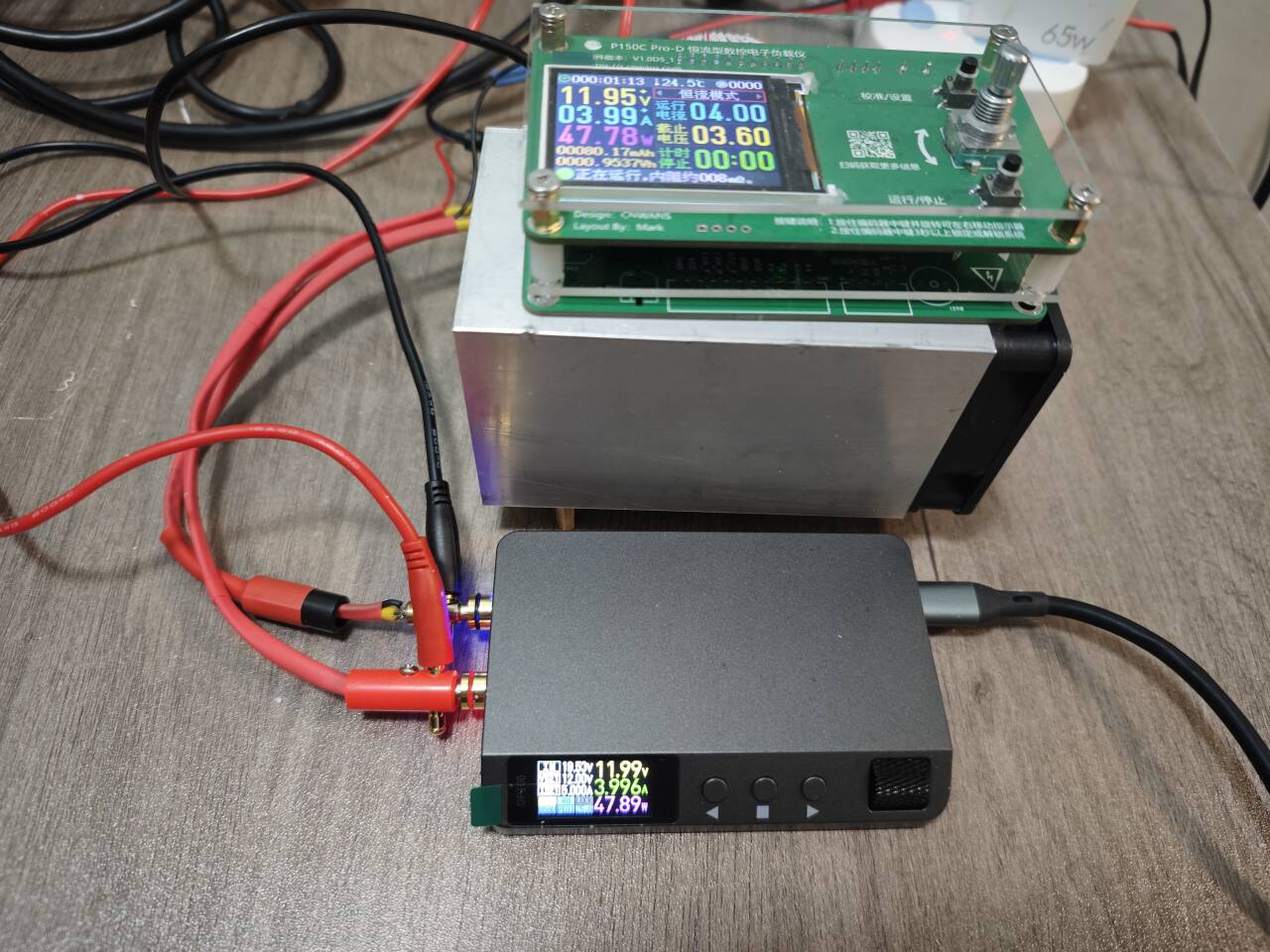
Test Description
The current structure is only tested up to 48W (12V4A). The temperature control starts at 35℃. During long-term testing, the NTC temperature sampling temperature is stable between 40-45℃. The fan maintains about 50% speed (speed feedback is about 2500rpm, and the fan's full speed is 5400rpm). The heat pipe is made of aluminum (60*60*100mm). The MOS is coated with silicone grease and directly attached to the heat pipe surface. A blowing-type heat dissipation method is used. The NTC temperature sampling resistor is close to the MOS package surface.
Version Iteration Notes
2024/3/24 Revision Content
(I) Test Results and Issues Found
1. During testing, a mismatch was found between the wiring terminals of the power board and the control board. The connection shown in the physical diagram is the only way to operate it conveniently. Since the current version will be significantly revised later, this issue will not be fixed.
2. During testing, it was found that the MOSFET was directly pressed against the heatsink, causing the heatsink to be shorted to the positive input terminal, resulting in the heatsink being energized. Please be careful during use; do not directly touch the heatsink or allow the control board's GND to contact the heatsink (the four holes on the control board are shorted to GND).
3. During testing, it was found that the negative input terminal of the power board was incorrectly shorted to GND, leading to abnormal current sampling.
4. The control board's download/communication interface silkscreen is incorrect.
5. The fan spins briefly upon power-on.
(II) Solutions
1. Update the control board and power board versions; update the control board to V1.1 and the power board to V1.1.
2. Revise and adjust the silkscreen on the control board and power board.
3. Power board schematic: CUR- changed to short-circuit with AGND.
4. Power board PCB: Screw holes 1 and 2 were moved upwards to avoid the fan mounting screws.
5. Power board PCB: Current-disconnected from GND at the terminal block; top layer of the wiring from the terminal block to the MOSFET was deleted; current sampling feedback wiring was revised; other wiring was slightly adjusted.
6. Structure: An attempt was made to add an insulating pad between the MOSFET and the aluminum heatsink, but testing revealed extremely poor heat dissipation. It is expected that an alumina ceramic sheet will be tested as an isolation material in V1.2.
Revisions on 2024/3/17:
1. V1.0 version modifications and design completed;
physical images of the board prototype released.


 京公网安备 11010802033920号

 SL2-022-S140/02-95


