Note: External driver board solution cannot solve screen flickering issues.
MiniDP signal input works correctly for both RTX 2070 and 780M. If you encounter display problems, please update your graphics card driver
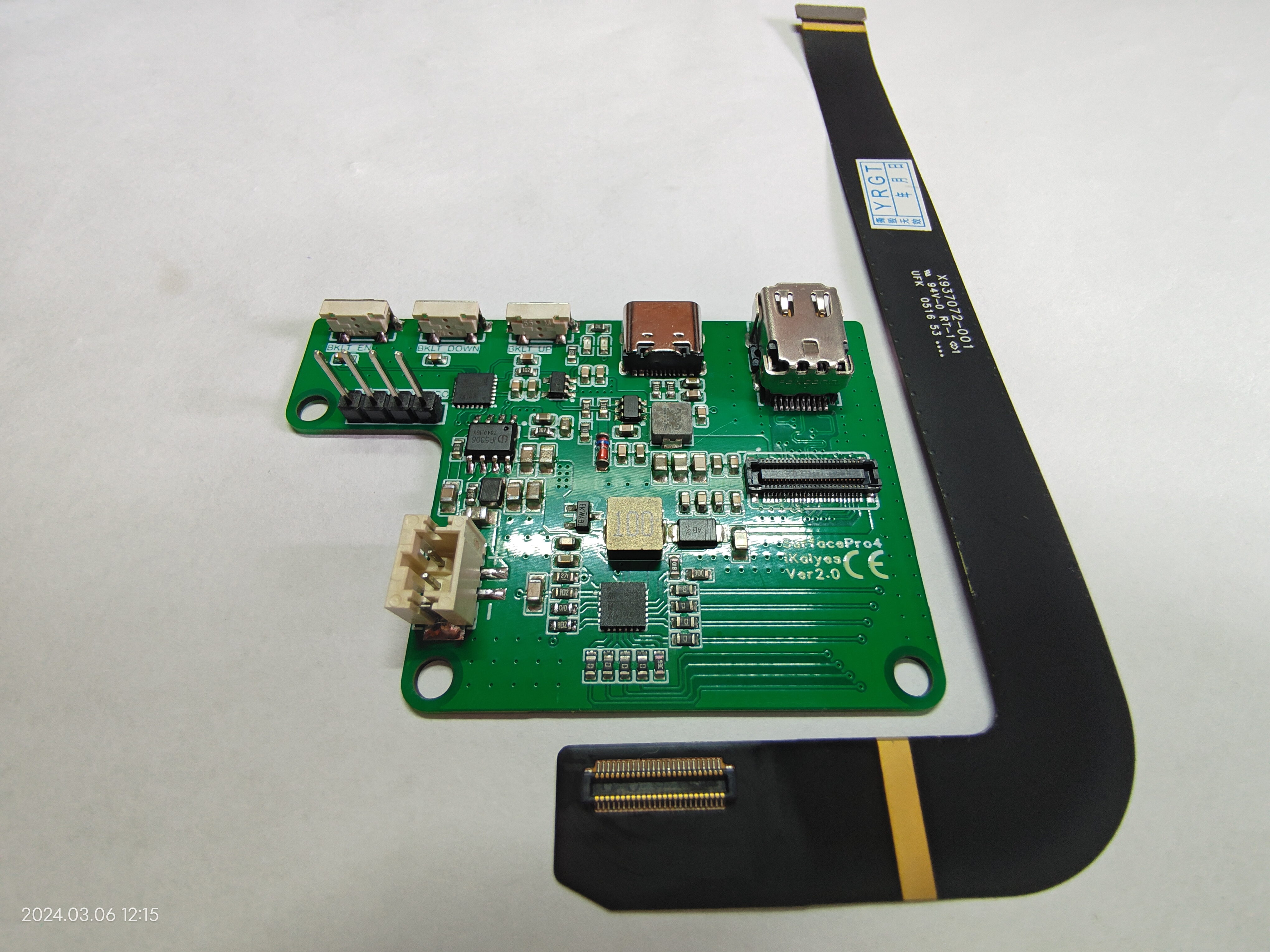
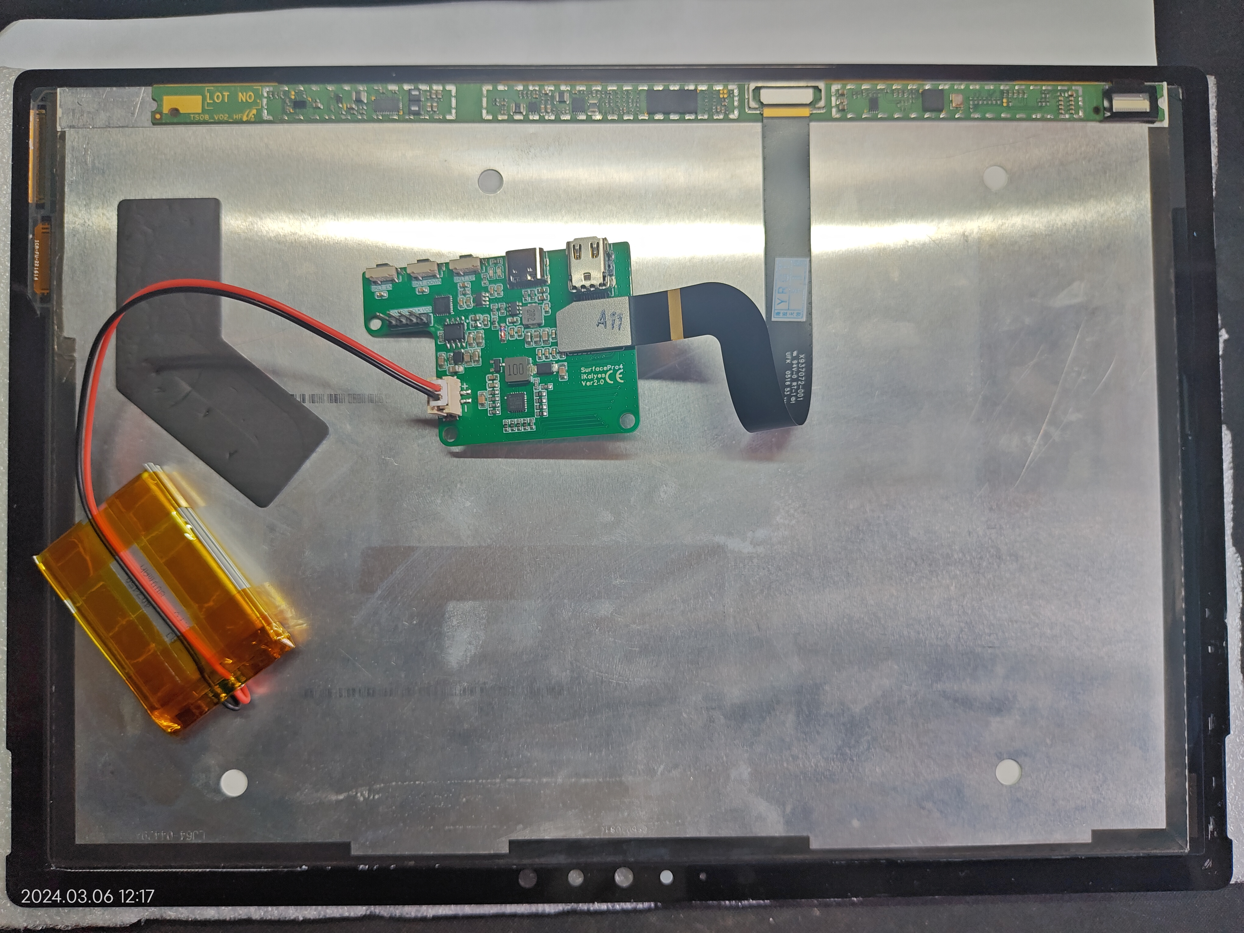
. Screen model: LTL123YL01-005;
Controller chip: STM32G031G8U6;
Backlight chip: MP3388S;
Battery management: IP5306
; DC-DC: TPS563201DDCR
; BTB female connector: Molex 51338-0574

SurfacePro4 (V2 firmware).elf
Surface Pro 4 (Source Code) - CUBEIDE.zip
PDF_SurfacePro4 Screen Driver Board.zip
Altium_SurfacePro4 screen driver board.zip
PADS_SurfacePro4 screen driver board.zip
BOM_SurfacePro4 Screen Driver Board.xlsx
93180
23rd RoboCon R1 Vehicle Circuit Design
The 23rd RoboCon R1 vehicle circuit design. The self-developed main controller, buck converter, and emergency stop system have been open-sourced on the platform.
1. Main Control Board Stack-Up Design:
Our R1 vehicle has a total of 16 motors, 2 DT35 controllers, 1 MID-360 controller, 4 solenoid valves, and various PCB modules. To effectively utilize space, we adopted an integrated stack-up design for the main control board, voltage divider, and CAN bus, as shown below:

We divided the control into two main control units based on the upper and lower layers. This improved our code debugging efficiency; in terms of circuit design, we completely separated the circuits for different mechanisms, which helped us with troubleshooting during the competition.
2. CAN Cable Details:
During our school debugging, we encountered CAN crosstalk issues, which may have been related to the overly dense power and CAN wiring. We finally solved the problem by switching to industrial 485 shielded twisted-pair cables. We carefully stripped the outer adhesive and shielding layer of the 485 twisted-pair cable, soldered the XH2.54 interface wire to the internal battery, and then further twisted the interface wire.

In the wiring, we also tried to separate the CAN wire and power wire as much as possible.
3. Reverse polarity protection, short circuit protection, and electrostatic discharge protection:
Fuse sockets were soldered and fuses were installed on each voltage divider board. A low-side reverse polarity protection circuit built with NMOS was also used. In circuits with many motors, we typically solder several capacitors onto the voltage divider board to ensure relatively stable bus voltage. At the main control interface, we also connected a TVS diode and an RC snubber circuit in parallel.

4. Summary:
The hardware group is a very detail-oriented group. For our hardware group, the biggest task is to ensure the circuit design is sufficiently stable. Seemingly simple layout and wiring actually involve many details. Through practice, we found that the short-circuit protection response speed of fuses is often not as fast as expected. To prevent hardware damage during debugging, we are also verifying an overcurrent protection module with a faster response speed.
PDF_23rd RoboCon R1 Vehicle Circuit Design.zip
Altium_23rd Robocon R1 Vehicle Circuit Design.zip
PADS_23rd Robocon R1 Vehicle Circuit Design.zip
BOM_23rd Robocon R1 Vehicle Circuit Design.xlsx
93181
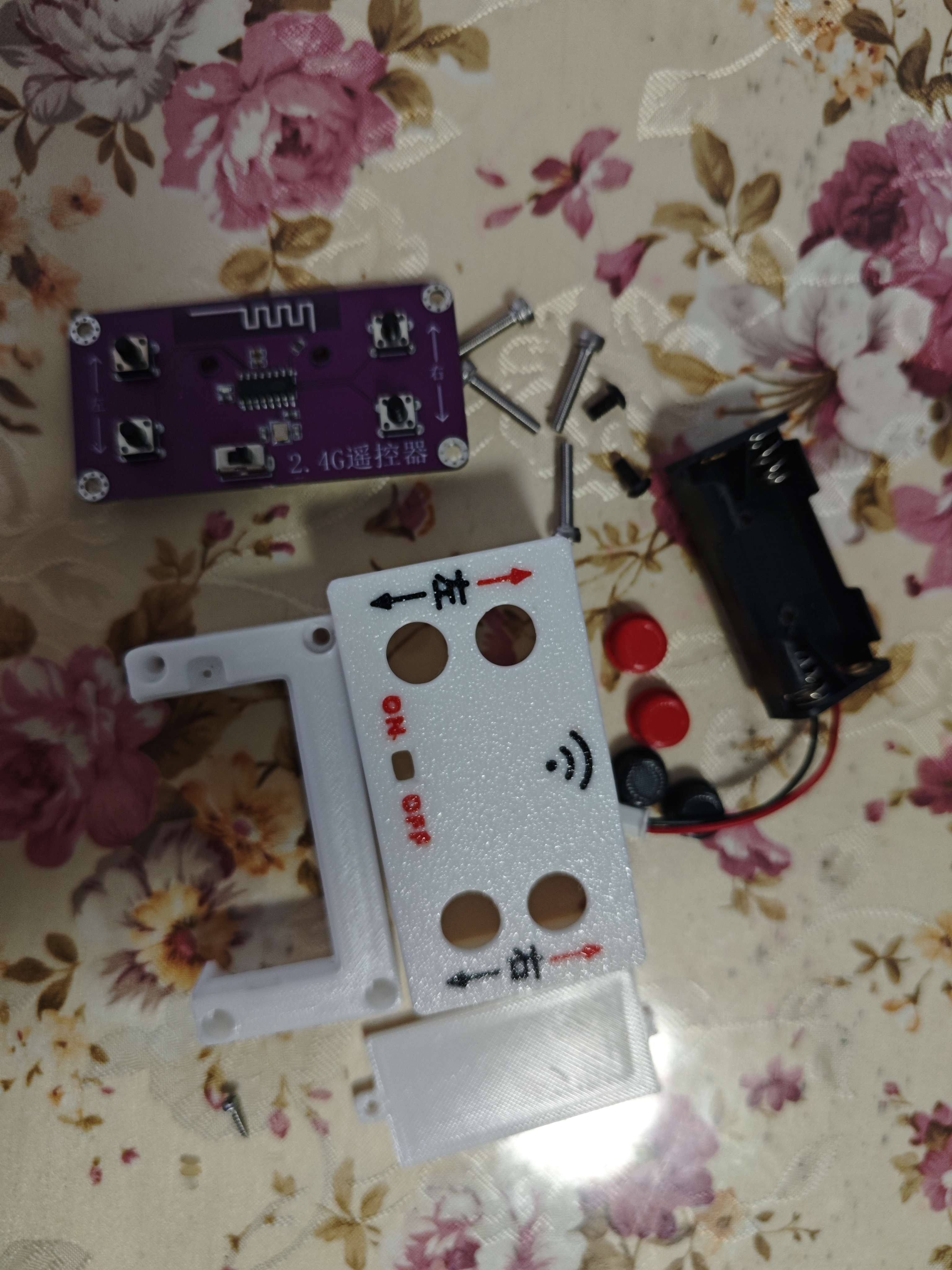
2.4G Four-Channel Remote Control - Transmitter - Receiver
This 2.4G four-channel remote control includes a transmitter and receiver, with four channels capable of controlling two motors. It can be used for simple remote control of small cars, controlling forward, backward, left, and right movement.
There are relatively few components, making soldering simple. The plug-in leads can be shortened for direct soldering on a heated board. The battery connector on the back needs to be soldered separately with a soldering iron. After soldering, the board can be cut open.

Prepare the following: four M3X18 cylindrical head screws, two M3X6 pan head screws, and a AAA battery compartment (2 slots).
Place the four buttons. Place
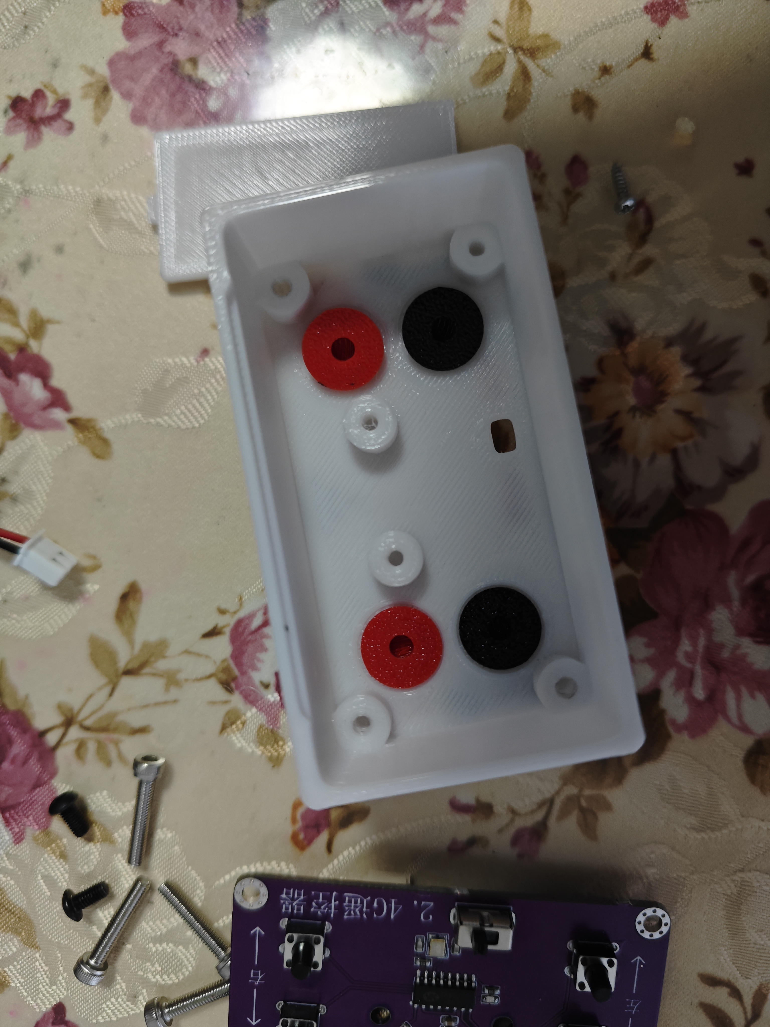
the board

on top. Connect the battery compartment.

Install the middle frame, paying attention to the battery compartment wiring.
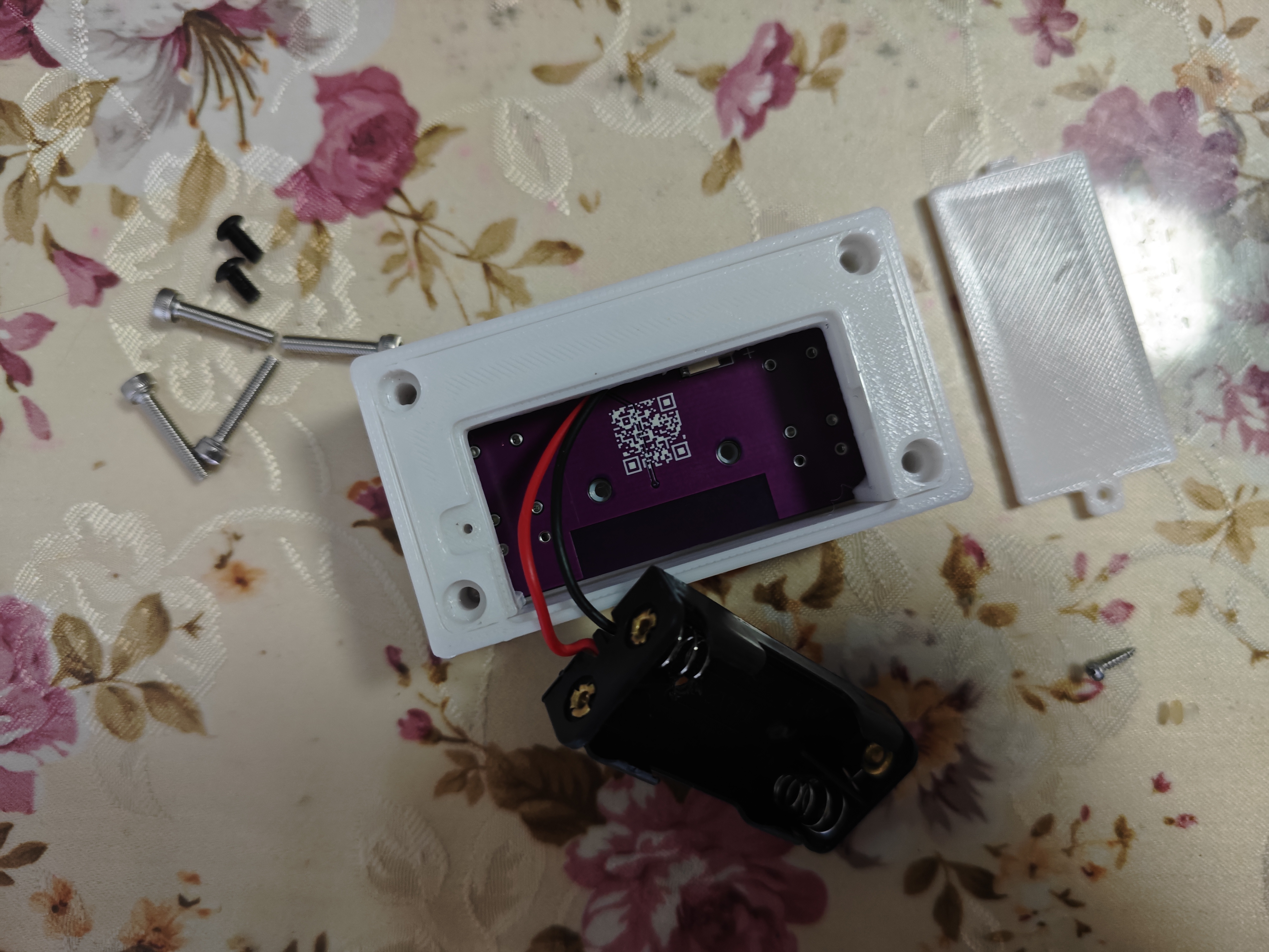
Insert the battery compartment and tighten the screws.
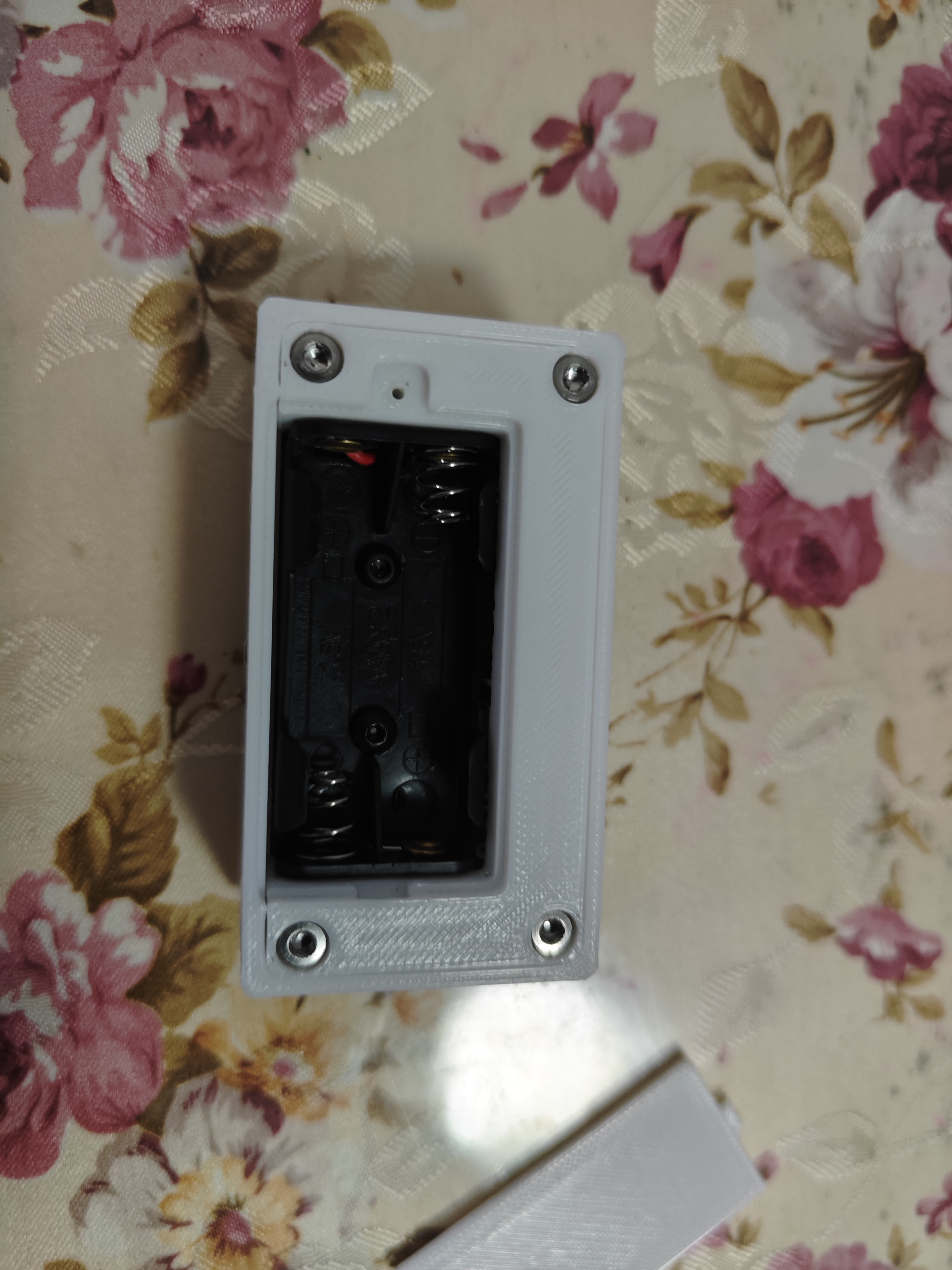
Install two AAA batteries.
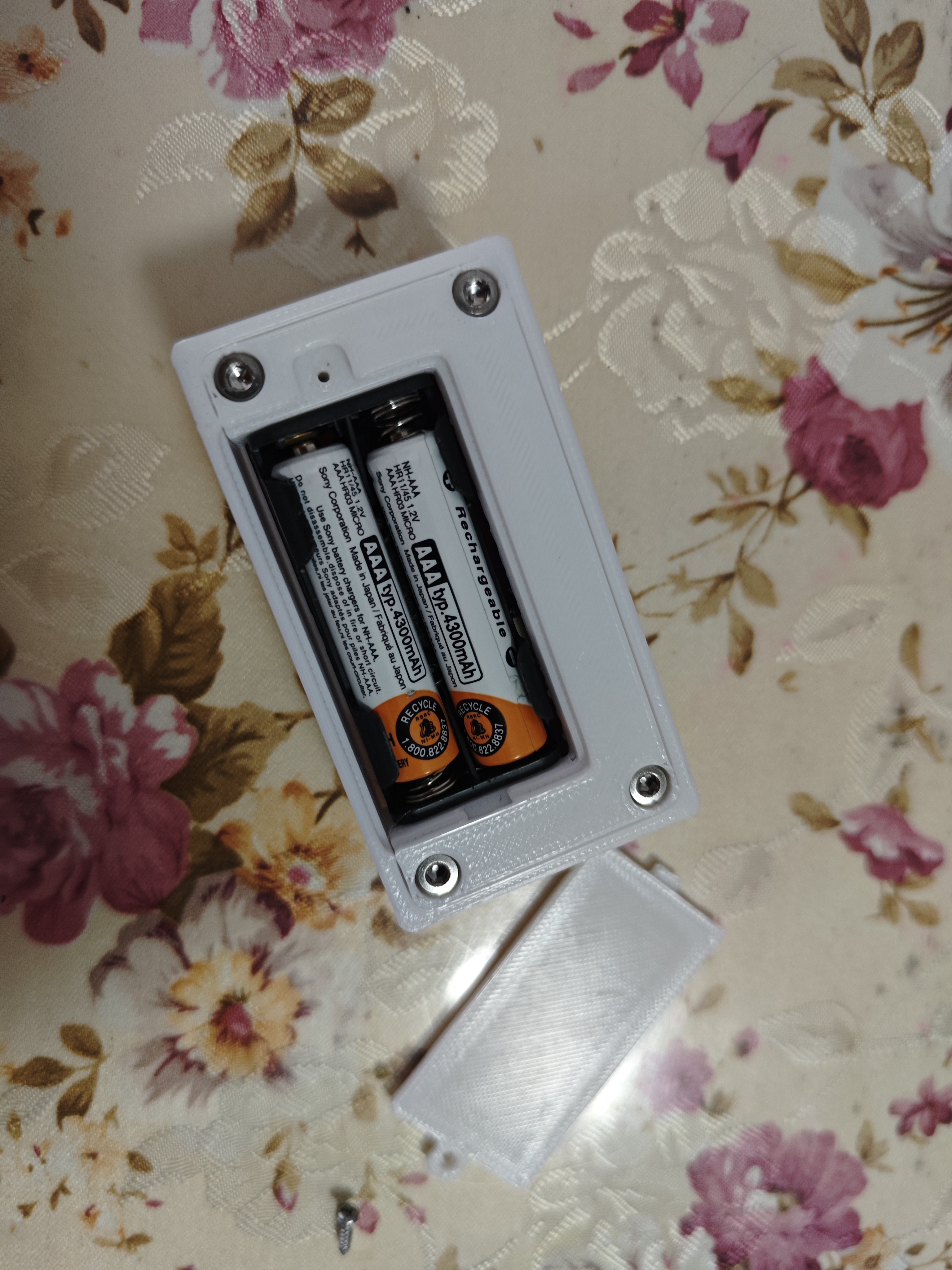
Install the battery cover and tighten the screws.
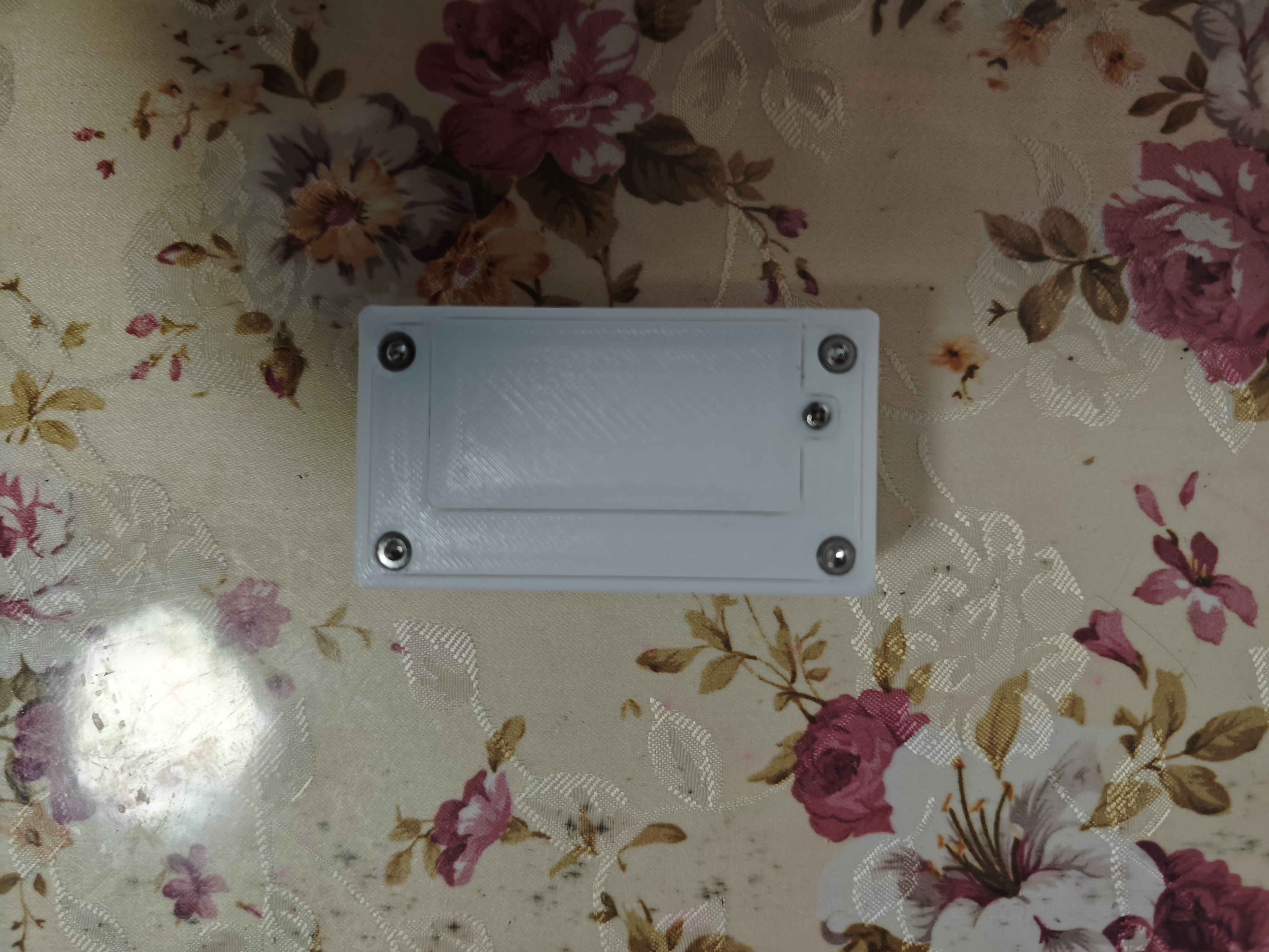
Front view.

PDF_2.4G Four-Channel Remote Control_Transmitter_Receiver.zip
Altium_2.4G Quad-Channel Remote Control_Transmitter_Receiver.zip
PADS_2.4G Quad-Channel Remote Control_Transmitter_Receiver.zip
BOM_2.4G Quad-Channel Remote Control_Transmitter_Receiver.xlsx
93182
electronic


 京公网安备 11010802033920号

 2100-1-218-36


