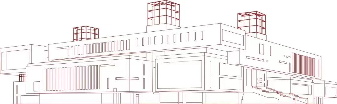
The TTP223E-BA6 touch chip is used to control the LED's illumination to create a light painting. The underlying solder mask layer of the light-transmitting area is exposed, and the light-transmitting area is marked as "no copper pouring on the front." Copper pouring is used on the remaining front part to prevent excessive light transmission. The image below is selected from the representative architecture of Nanjing University of Science and Technology: the Bay and the Yifu Library.

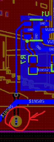
The touch switch button is directly connected to a wire from pin 3 of U1 and then connected to several vias (as indicated by the arrows in the image below). After the final product is powered on, touching those vias will switch the LED on and off.
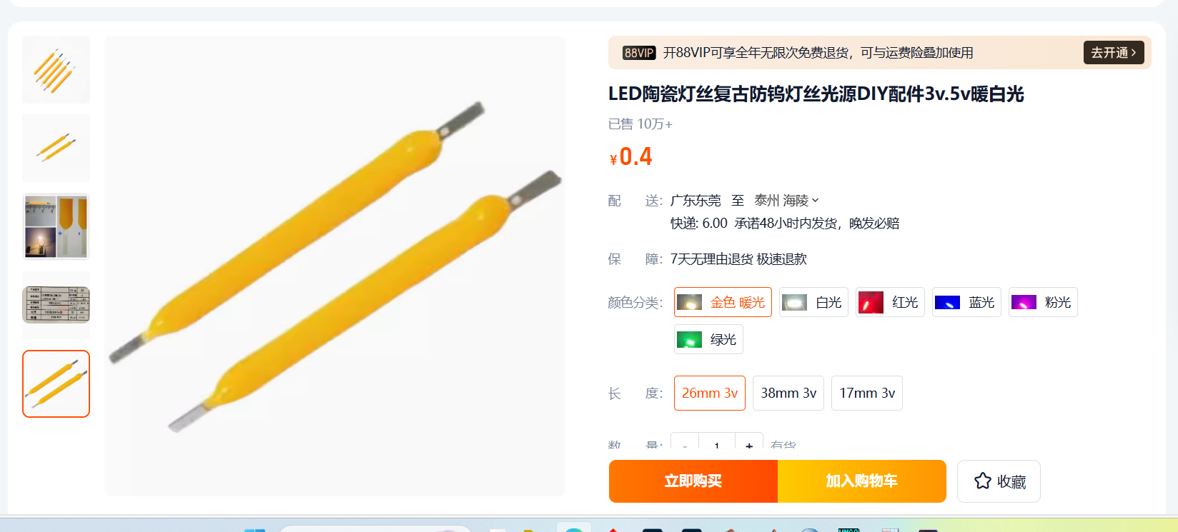
The LED uses a 26mm, 3V LED ceramic filament, and a warm gold light is recommended, as shown in the image below.
VID20240808182637.mp4
PDF_Southern University of Technology Campus Light Paintings.zip
Altium_Southern University of Technology Campus Light Painting.zip
PADS_Southern University of Technology Campus Light Painting.zip
BOM_Southern University of Technology Campus Lighting Painting.xlsx
93232
9th LCSC Electronics Design Contest #Desktop Temperature and Humidity Monitor Type-C Charger 6925297A
Based on LCSC's #Desktop Temperature and Humidity Sensor Training Camp, this design abandons 3V dry batteries and adopts Type-C charging + 18650 lithium batteries.
The original project
used dry cell batteries as its energy source, but in this era dominated by new energy development, it's necessary to respond to the call of the times and abandon traditional dry cell batteries to reduce environmental pollution and lower battery costs.
Advantages include large
rechargeable
battery capacity,
long battery life,
and support for up to 5V 2A charging. Modifications
were made to address the issue of series connection causing charging failures. The battery power supply circuit was changed from series to parallel connection to achieve charging functionality.
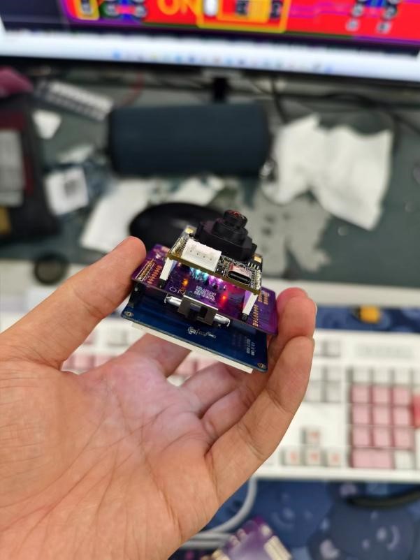
A physical
monitoring device and charging demonstration video are provided.
WeChat_20240808203642.mp4
WeChat image_20240808203706.jpg
WeChat image_20240808204037.jpg
WeChat image_20240808204047.jpg
WeChat image_20240808204054.jpg
PDF_9th LCSC Electronics Design Contest #Desktop Temperature and Humidity Monitor Type-C Charger 6925297A.zip
Altium_9th LCSC Electronics Design Contest #Desktop Temperature and Humidity Monitor Type-C Charger 6925297A.zip
PADS_9th LCSC Electronics Design Contest #Desktop Temperature and Humidity Monitor Type-C Charger 6925297A.zip
BOM_9th LCSC Electronics Design Contest #Desktop Temperature and Humidity Monitor Type-C Charger 6925297A.xlsx
93233
Open ART screen expansion board
An OpenART screen expansion board with battery and charging circuitry.
Utilizing the IP5305T charging chip, it features 1.0A synchronous boost conversion and 1.2A synchronous switching charging, supporting low-power servos. The boost efficiency reaches up to 91%, and the charging efficiency up to 93%. The chip temperature reaches 56.2℃ after 30 minutes of charging
. [Image 5.jpg]

Built-in power path management supports simultaneous charging and discharging without affecting the normal operation of Open ART. It includes a TYPE-C CC pull-down pin, compatible with CC cable charging and
supporting 4.20/4.30/4.35/4.40V batteries. A four-LED power indicator is included
. [Image 6.jpg]
It is compatible with 1.8-inch and 2.0-inch displays
. [Image 1.jpg]

A BOOT pin is brought out for easy debugging, and power can be controlled via a button or a toggle switch.
PDF_Open ART Screen Extension Board.zip
Altium_Open ART Screen Expansion Board.zip
PADS_Open ART Screen Expansion Board.zip
BOM_Open ART Screen Expansion Board.xlsx
93235
JW5033 SMD step-down module
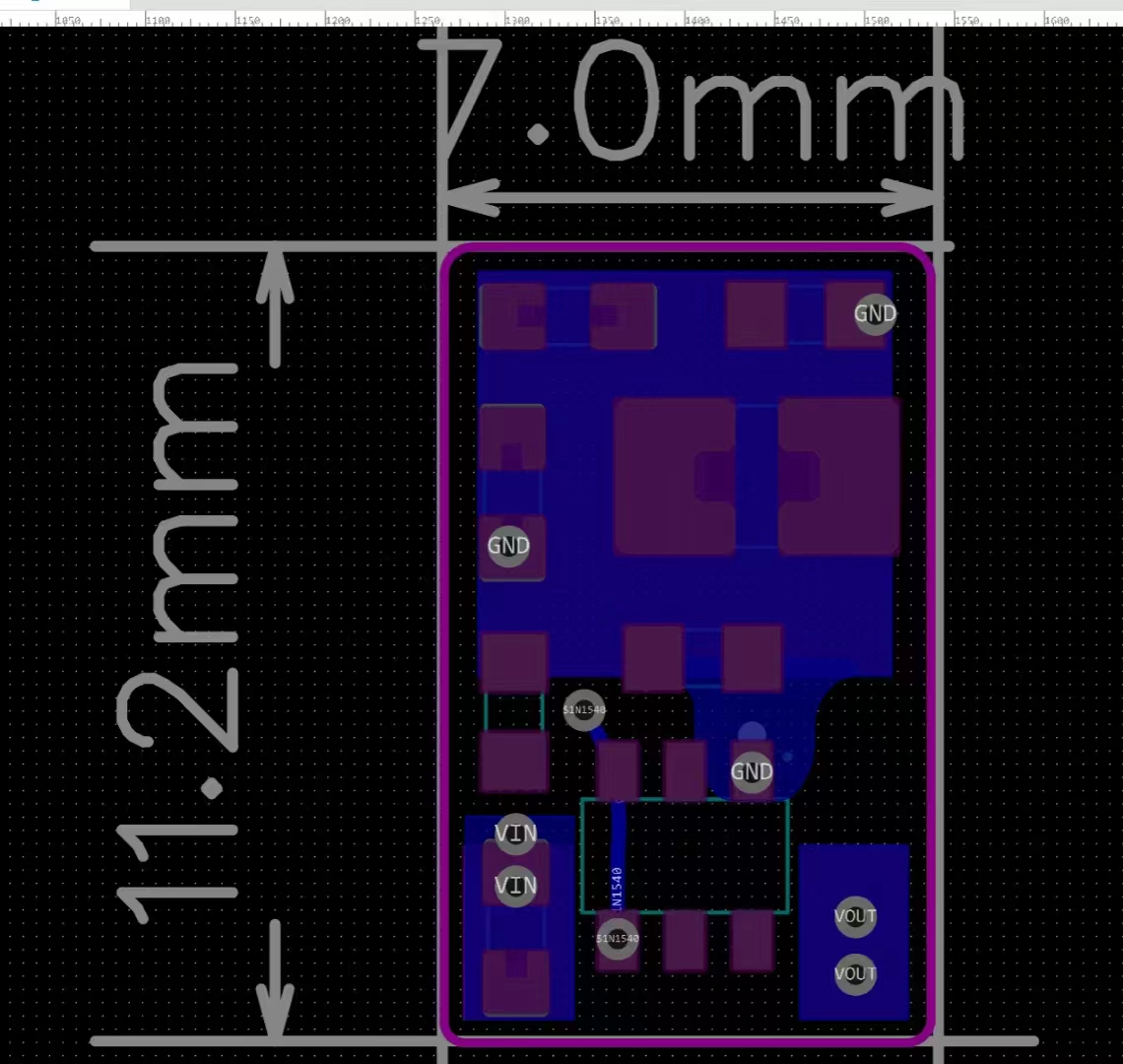
This is a very small DC-DC step-down module based on the JW5033T. Input voltage range: 4.7-18V; output voltage range: 3.3-7V; full load: 0.6A@3.7V;
dimensions: 11.2*7mm; TO-252 compatible.
The JW5033T-based DC-DC step-down module
has an input voltage range of 4.7-18V and an output voltage range of 3.3-7V
. Due to size limitations, the inductor saturates at 0.65A output current. For replication,
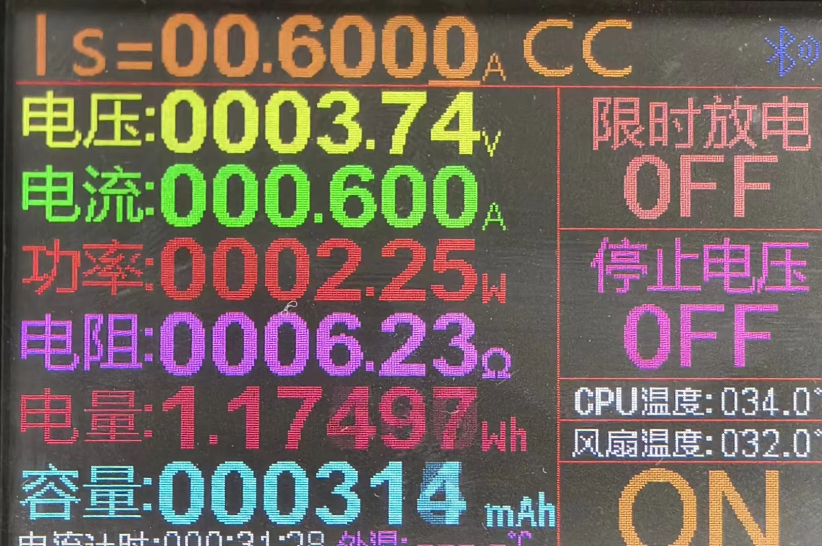
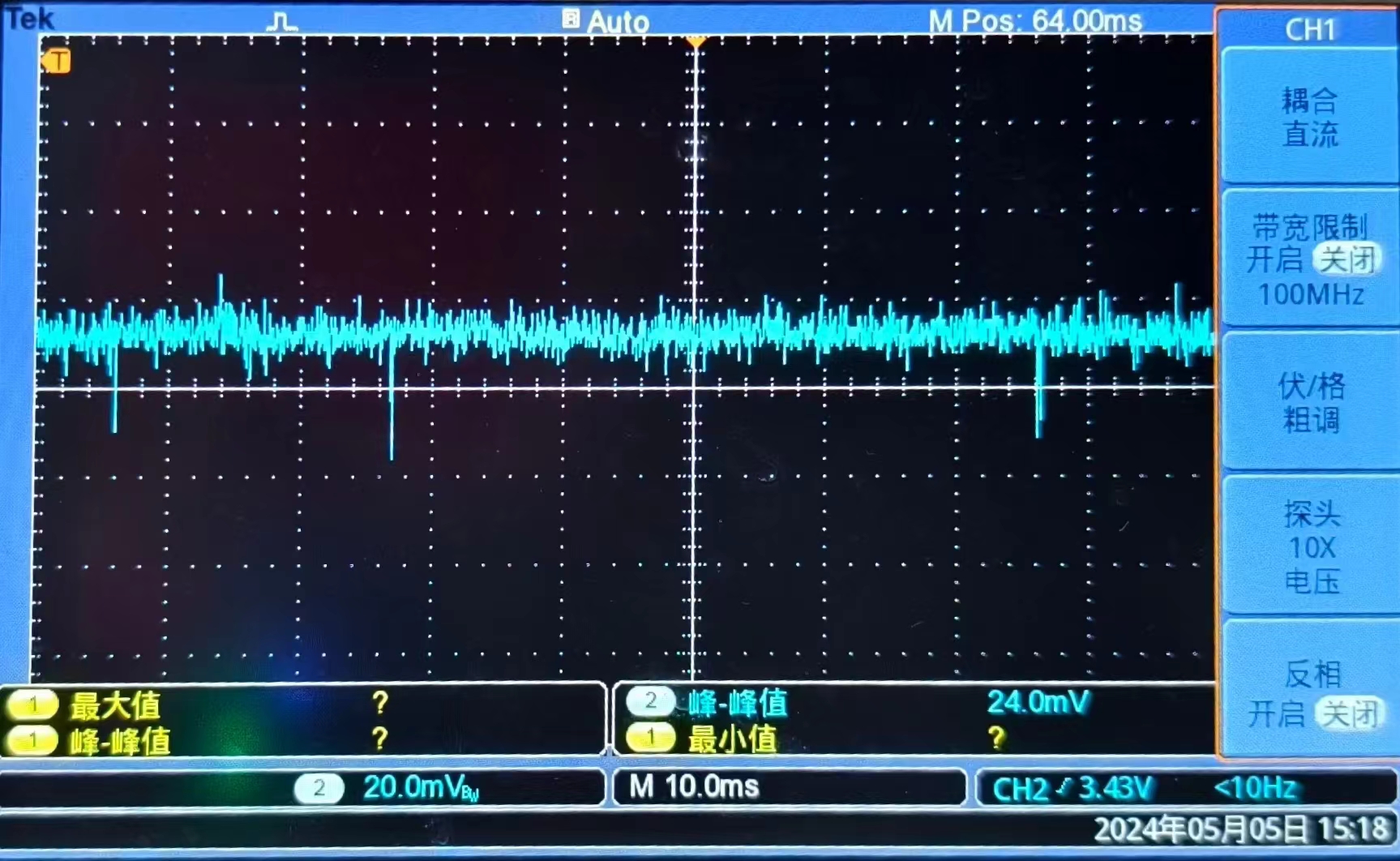
an inductor with a higher saturation current can be replaced. The module is 11.2*7mm in size and compatible with TO-252 packages. The full-load ripple is 24mV. It can directly replace LDO chips such as the 7805. After
30 minutes of full-load operation, the highest temperature reached 67.3℃.

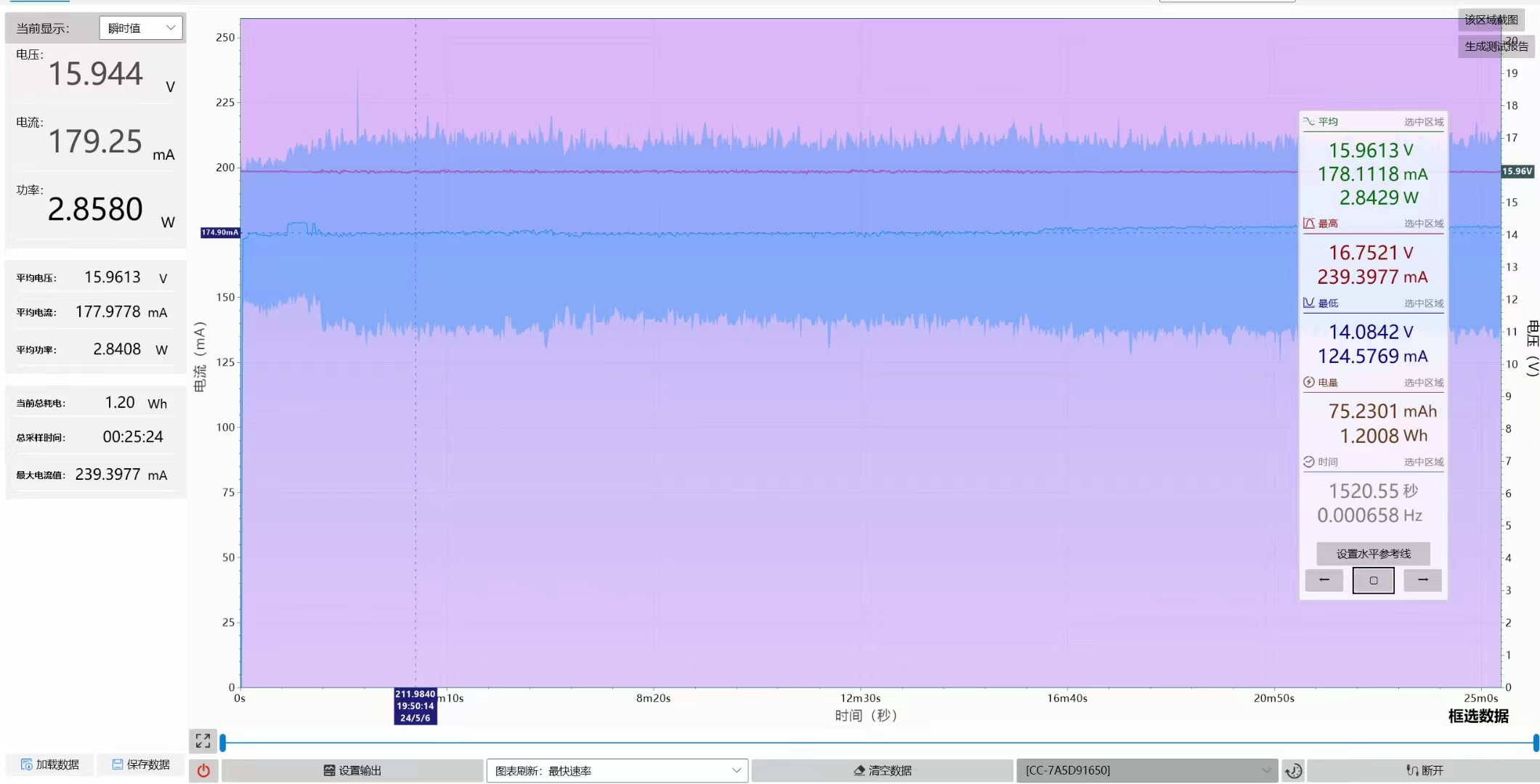
The power conversion efficiency at 0.6A from 16V to 3.75V is 83.6% (including line loss).
The output voltage can be modified by changing the values of resistors R2 and R3; please refer to the chip datasheet for details.

JW5033T_Datasheet (from JWAT).pdf
PDF_JW5033 SMD Step-Down Module.zip
Altium_JW5033 SMD step-down module.zip
PADS_JW5033 SMD step-down module.zip
BOM_JW5033 Surface Mount Step-Down Module.xlsx
93236
NAE12S17 step-down module
A DC-DC step-down circuit based on NAE12S17 has a full-load efficiency of 86.4% (Vin=12.1V, Vout=5.01V, Iout=12A) and can work stably for 6 hours without active heat dissipation when outputting 11.5A.
Product Overview:
This project is a DC-DC power module based on the NAE12S17-B packaged (PSiP) chip.
The input voltage range is 3V-14V, the output voltage range is 0.6-5.5V, the maximum designed output current is 17A, and the measured maximum output current is 12A.
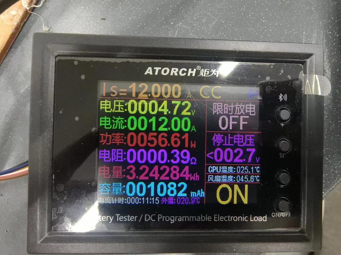
The output can be sustained at full load (12A).
The font color can be changed by modifying the hexadecimal color system.
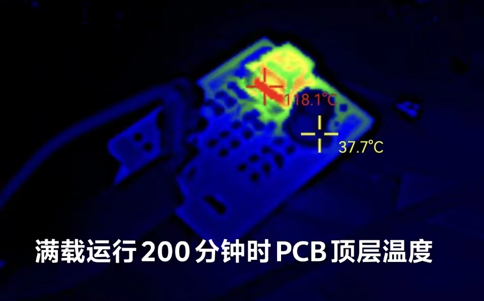
After 200 minutes of full load operation, the highest temperature on the top layer of the PCB was 118.1 degrees Celsius, and the highest temperature on the bottom layer was 135.2 degrees Celsius.

It features input undervoltage protection, output overcurrent protection (hiccup mode), output short-circuit protection (hiccup mode), and overtemperature protection (self-recovery).
The switching frequency can be selected as 600K or 1000KHz by modifying the resistance to ground on the MODE pin.
This module has a relatively high no-load current of approximately 0.14A, and is recommended for use under conditions requiring low voltage and high current. To ensure the normal operation of the module, it is recommended to provide it with a suitable heat dissipation environment.
NAE12S17 Chip Manual (from Huawei Digital Power).pdf
PDF_NAE12S17 step-down module.zip
Altium_NAE12S17 step-down module.zip
PADS_NAE12S17 step-down module.zip
BOM_NAE12S17 step-down module.xlsx
93237
8.14-inch SES4-color price tag driver board
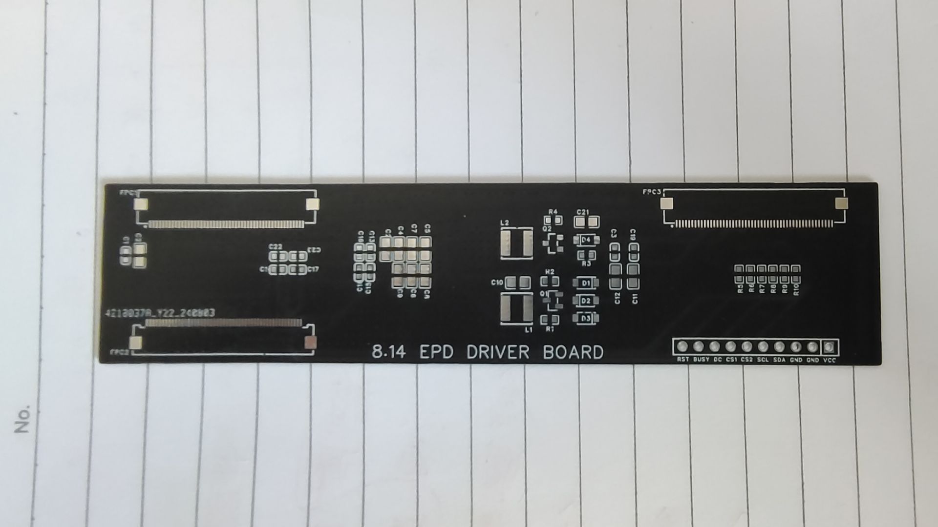
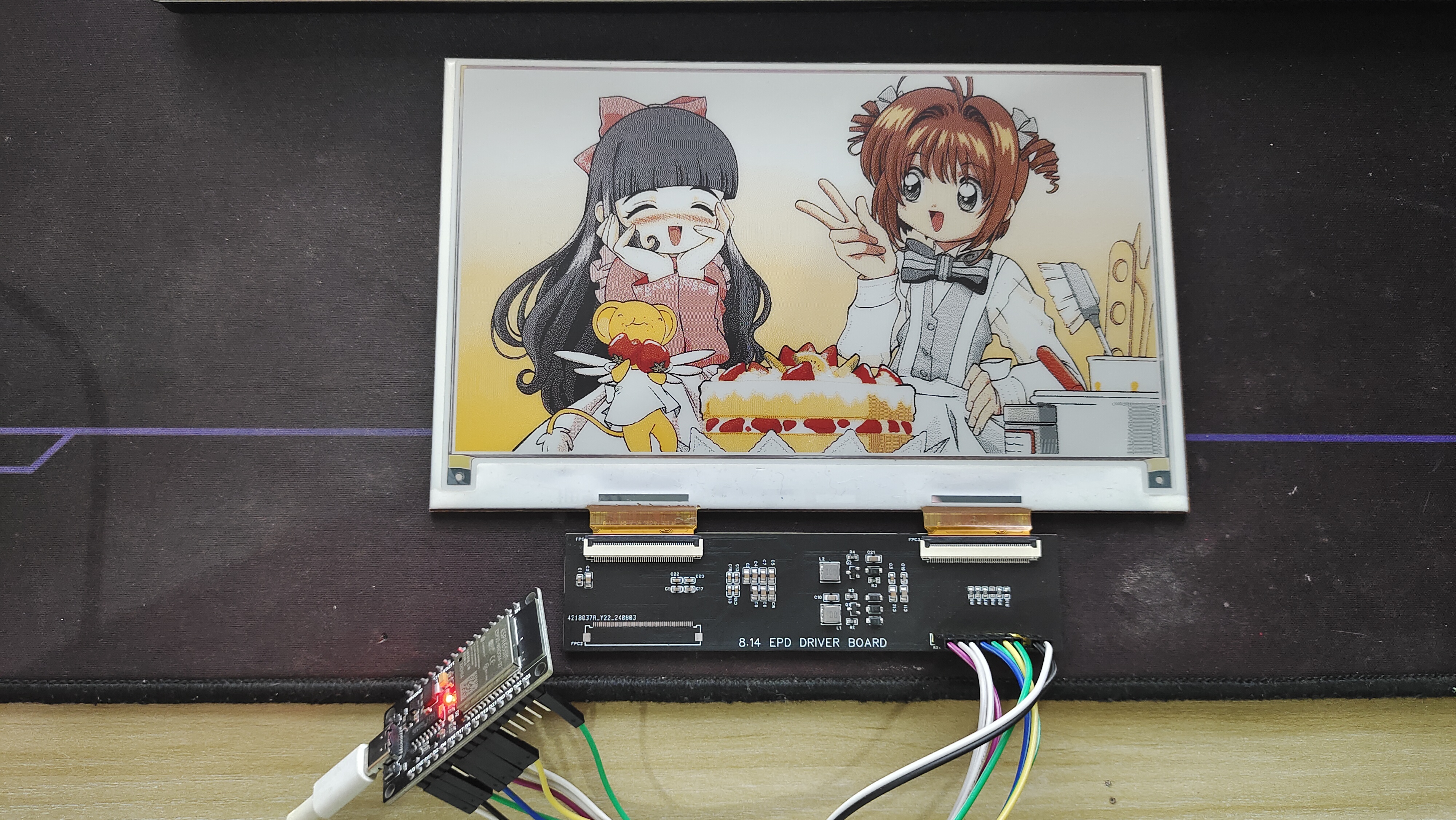
8.14-inch 4-color SES electronic price tag e-ink screen driver board
This is an 8.14-inch 4-color SES electronic shelf label e-ink screen driver board with dual ICs (IC suspected to be JD79686AB) and dual ribbon cables. Theoretically, it can also be used with 6-color boards of the same size. It comes with an adapter FPC, with pins identical to those in the Waveshare 7.3G, where the CS pin of the IC is located on pin 34.
PDF_8.14-inch SES4-color price tag driver board.zip
Altium 8.14-inch SES4-color price tag driver board.zip
PADS 8.14-inch SES4-color price tag driver board.zip
BOM_8.14-inch SES4 color price tag driver board.xlsx
93239
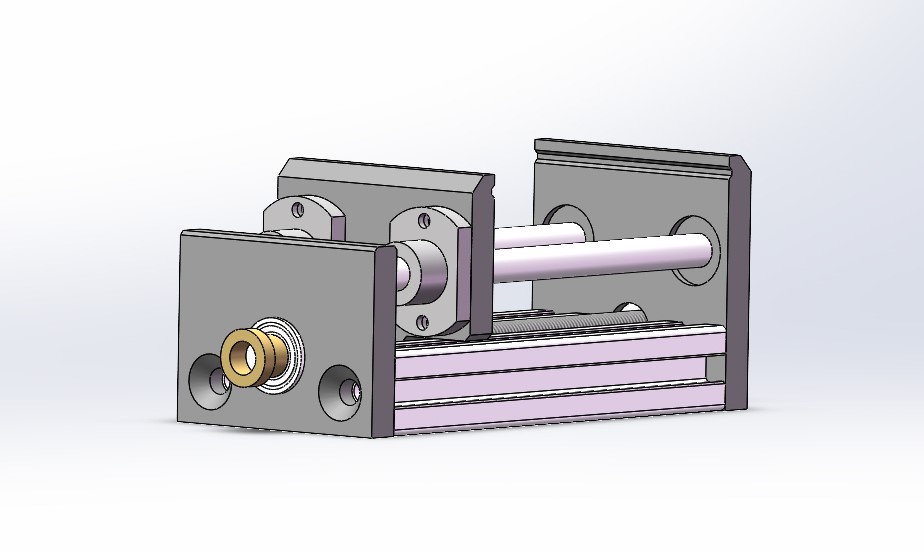
35 Closed-loop stepper motor driver board && vise control board
This project used CNC sheet metal and some mechanical parts to fabricate an electric welding vise. The CNC components were prototyped at JLCPCB's 1 Yuan CNC prototyping event. The drive section uses a closed-loop stepper drive, and the motor drive board is suitable for a 35 stepper motor.
Project Introduction:
This project utilizes CNC sheet metal and some mechanical parts to construct an electric welding vise. The CNC components were prototyped at JLCPCB's 1 Yuan CNC prototyping event. The drive system uses a closed-loop stepper drive, and the motor drive board is compatible with a 35 stepper motor. It can be used in other projects. The plan includes the following functions: closed- loop button setting for
vise position, automatic adjustment of clamping current (to be implemented), long-term automatic sleep mode (to be implemented), external control input (to be implemented), and manual version video demonstration: bilibili. Software open-source address: github. Software part references "Contradictory Aggregator". Hardware open-source address: oshwhub. Hardware part references "HyperStepper" . Bill of Materials : 1. Components required for the circuit board (BOM) are given . 2. Structural part: Item No. Name Quantity Link 1 CNC aluminum plate 3 JLCPCB CNC prototyping 2 2020 aluminum profile 120mm tapped at both ends M6 2 Reference Connection 3 8mm optical shaft 130mm (no burrs at both ends) 2 Reference Connection 4 Double-edged flange linear bearing 8x15x24 2 Reference Connection 5 T8 lead screw 143mm pitch 2 lead 8 1 Reference Connection 6 Miniature flange bearing F688Z (8*18*5) Manual: 2 / Electric: 1 Reference Connection 7 Backlash-free nut T8 lead 8 1 Reference Connection 8 T8 lead screw lead screw nut pitch 2 lead 8 1 (Generally included with the purchase of a lead screw) Reference connection 9 Coupling 5*8 Manual: 0 / Electric: 1 Reference connection 10 M6x14 Screw 4 11 M3*12 *4 (head diameter) Small head screw 10 12 35 Stepper motor Manual: 0 / Electric: 1

model.zip
Demo video.mp4
model modified version.zip
PDF_35 Closed-Loop Stepper Motor Driver Board & Vise Control Board.zip
Altium_35 Closed-Loop Stepper Motor Driver Board & Vise Control Board.zip
PADS_35 Closed-Loop Stepper Motor Driver Board & Vise Control Board.zip
BOM_35 Closed-Loop Stepper Motor Driver Board & Vise Control Board.xlsx
93240
electronic


 京公网安备 11010802033920号

 HF18FF/012-2Z5XXX


