I found an unused chip in the box, but I didn't want it to just sit there, so I made this. Please point out any mistakes *T_T*.
![648a3a9b8885544e459729efefe69a31.jpg]
![b7b78b703738e4e726d373f7b700a6e7.jpg]
PDF_STM32F427 Minimum System Board.zip
Altium_STM32F427 Minimum System Board.zip
PADS_STM32F427 Minimum System Board.zip
93684
STM32F103ZE+ESP32
The STM32F103ZE and ESP32 are drawn on the same circuit board.
The STM32F103ZE and ESP32 are designed on the same circuit board. All resistors and capacitors use 0805 or larger packages for easy DIY soldering.
The STM32 and FPGA are connected via serial port.
The circuit has been verified through actual soldering; please use it with confidence.
PDF_STM32F103ZE+ESP32.zip
Altium_STM32F103ZE+ESP32.zip
PADS_STM32F103ZE+ESP32.zip
BOM_STM32F103ZE+ESP32.xlsx
93685
STC8 Learning Board
This project is an STC8 learning board that integrates running lights, digital tubes, buttons, AD conversion, DA conversion, buzzer, AT24C02 memory, DS18B20 temperature detection, and 12864 and 1602 LCD displays. It is suitable for students who are new to 51 microcontrollers.
As a learning board, its functions are shown in the figure below. It includes essential modules for beginners in 51 microcontrollers.

Here are some points to note in circuit design
: 1. Please select a 10uF decoupling capacitor for CH340 (instead of the 100nF commonly used in many schematics; this may also be a problem with my circuit). Otherwise, the computer will not be able to recognize the USB device.
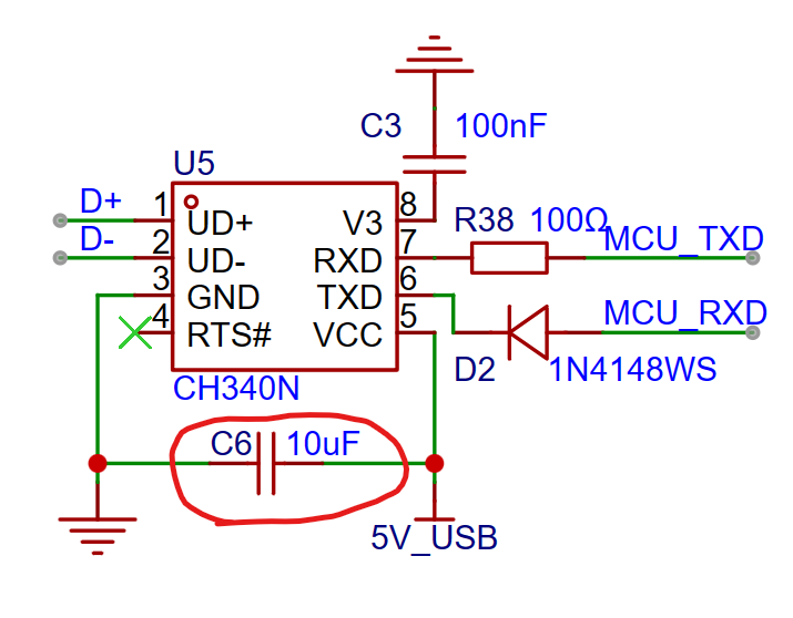
2. CH340's RXD and TXD correspond to the MCU's TXD and RXD. Also, to ensure STC chip cold start, a small resistor needs to be connected in series on the CH340's RXD pin, and a diode in series on the TXD pin. Otherwise, CH340 will supply power to the chip and energize VCC. Actual measurements show that without the resistor and diode, VCC is approximately 3V (power supply is 5V).

3. For the Type-C interface design, please follow the official documentation specifications (CC1 and CC2 must be connected to a 5.1kΩ resistor before grounding, DP and DN must be connected to a 33Ω resistor before connecting to CH340).
Experts in the technical group generally believe that the resistors on CC, DP, and DN are unimportant in low-speed circuits, but should be included in high-speed circuits. However, I once saw a Bilibili user say, "Type-C can still be used without a resistor connected to the CC pin; that's a blessing from Type-C." This shows that you still have to follow the official documentation, otherwise you might make mistakes.

Some points to note in my circuit design
: 1. Since the STC8H8K64U chip does not have P1.2, I used P5.2 as P1.2. When writing the program, pay attention to this.
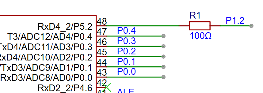
Taking the AD conversion code as an example, the following code can be used to read data:
adval=P1&(0xFB|P5);
2. When using port P3.6, set it to weak pull-up, and P4.2 to high impedance input; when using port P4.2, set it to weak pull-up, and P3.6 to high impedance input; when using port P3.7, set it to weak pull-up, and P4.4 to high impedance input; when using port P4.4, set it to weak pull-up, and P3.7 to high impedance input.
3. To ensure the buzzer power, the GPIO controlling the active buzzer should be set to push-pull output. The default quasi-bidirectional port's drive capability is insufficient.
The port operating mode configuration is as follows:
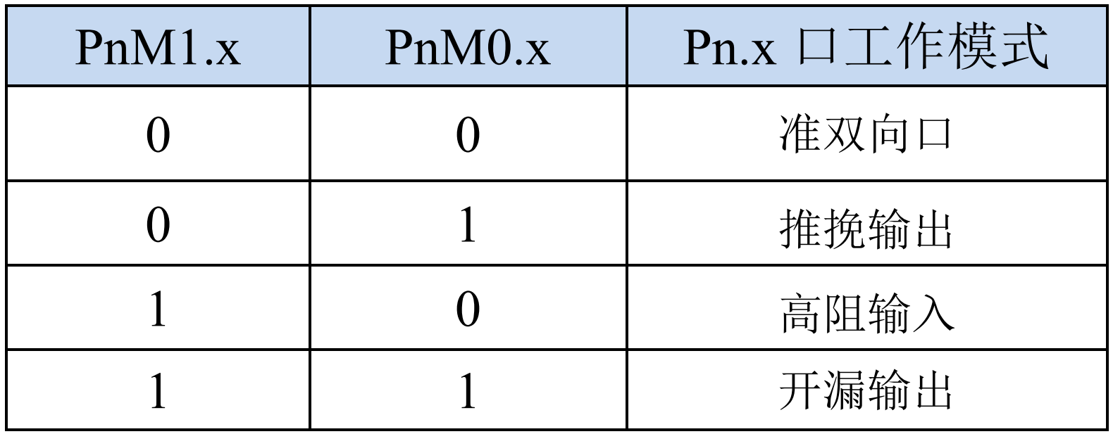
4. The DAC0832 outputs current. To observe the change in output current, please use a red LED. Do not use green or blue LEDs, as these require a larger current to light, and the DAC0832 may not be able to drive them.
5. Program Download: With the chip powered off, import the generated hex file into the STC program download software, click "Download/Programming," and then power on the chip. The chip will complete the program download while powered on.
Some attached
instructions include: Sample Program.rar; Partial Case Program I wrote;
STC8H8K64U-STC89-DEMO-CODE-20230116.rar; Official STC-Dog-Beating Stick Series Core Experiment Board Case Program
Basic Module Program.rar; Guo Tianxiang 51 Microcontroller Learning Board Accompanying Case Program;
STC8 Introduction Manual.pdf; STC8 Series Microcontroller Technical Reference Manual. For
demonstration videos, please refer to the Bilibili video: [STC8 Learning Board Case Demonstration]. https://www.bilibili.com/video/BV1z7bCeHEuM/?share_source=copy_web&vd_source=1cc6752786a7dd940c6c809a85212bba
Finally, I sincerely request that all experts leave their valuable opinions.
Sample Program.rar
STC8H8K64U-STC89-DEMO-CODE-20230116.rar
Basic Module Program.rar
STC8 Introduction Manual.pdf
PDF_STC8 Learning Board.zip
Altium_STC8 Learning Board.zip
PADS_STC8 Learning Board.zip
BOM_STC8 Learning Board.xlsx
93686
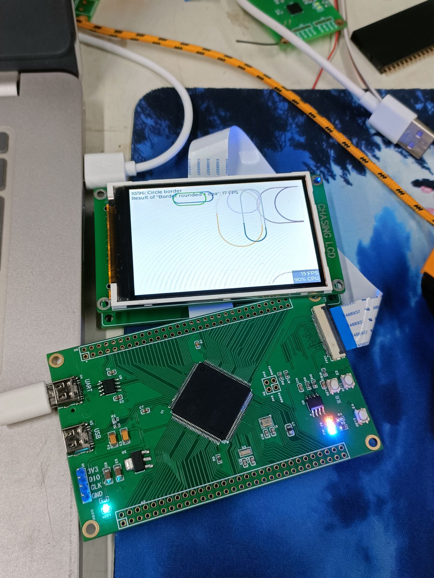
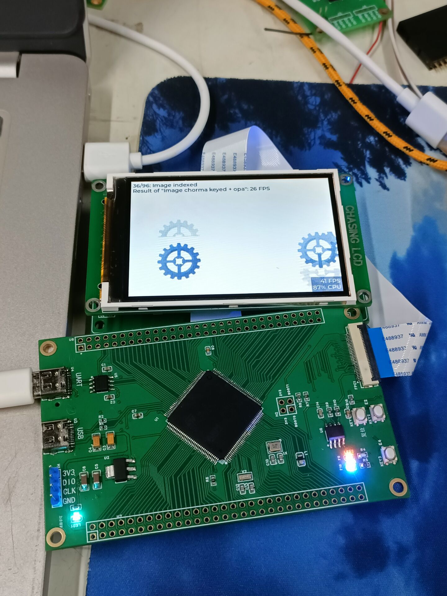
STC32 Development Board - Can use Puzhong Development Board as a hardware expansion tool
STC32 core board
I bought this development board when I was learning 51 microcontrollers, and it's been gathering dust for a long time. I can finally use it to learn STC32.
It integrates a minimum system, USB download, NTC temperature measurement, and serial screen communication.
It can be directly plugged into a 51 development board.
aeefd98eabbc5776bead0faeb5411091.mp4
PDF_STC32 Development Board - Can use Puzhong development board as hardware expansion.zip
Altium STC32 Development Board - Can be used as a hardware expansion tool with Puzhong Development Board. (zip)
PADS_STC32 Development Board - Can be used as a hardware expansion tool with Puzhong development board. (zip)
BOM_STC32 Development Board - Can use Puzhong development board as hardware expansion.xlsx
93687
#Bootcamp# Simple Digital Oscilloscope Project Based on STM32 - 1777544A
Design a beginner-level digital oscilloscope project using an STM32F103C8T6.
This project is a beginner's guide to designing a digital oscilloscope using the STM32F103C8T6. Following the steps-by-step instructions from JLCPCB instructors, the project was successfully completed, and all functions were implemented.
Simple Oscilloscope STM32 Version.rar
WeChat_20240402202836.mp4
PDF_#Bootcamp#Simple Digital Oscilloscope Project Based on STM32 - 1777544A.zip
Altium_#bootcamp#Simple Digital Oscilloscope Project Based on STM32 - 1777544A.zip
PADS_#Training Camp# Simple Digital Oscilloscope Project Based on STM32 - 1777544A.zip
BOM_#Training Camp# Simple Digital Oscilloscope Project Based on STM32 - 1777544A.xlsx
93688
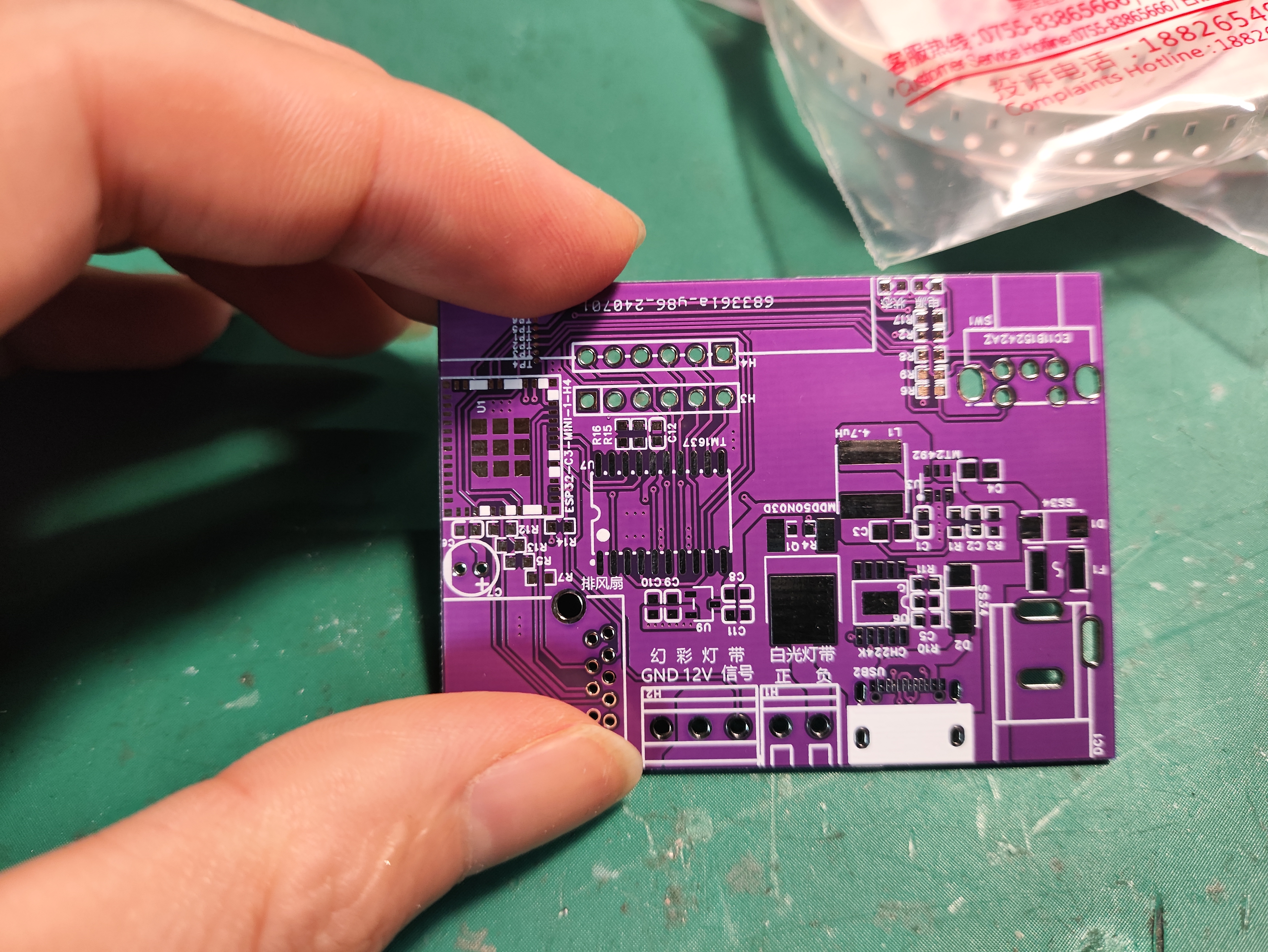
[Smart Home] ESPHOME Welded Exhaust Fan and Desktop Ambient Light Controller: A Frankenstein's Monster
A Frankenstein's monster based on the ESP32-c3-mini.
I previously bought a high-performance fan to use as a welding exhaust fan; it was incredibly fast when turned on. The fan supports PWM signal speed control, but I hadn't bought a speed control module yet. Recently, I wanted to add RGB lighting to my desk. So, I thought I'd just combine the controls for these two components. Here's the approach: I used an ESP32-C3-MINI I already had as the main controller, and I needed an EC11 rotary encoder for operation. Considering the installation method, I used a horizontal mounting. I also needed a display. I initially planned to use an SSD1306 screen, but considering the need for clear visual feedback and the fact that 1306 screens aren't easy to mount, I opted for a 4-digit LED display. I used the TM1637 chip, which is directly supported by ESPhome. The fan is 12V, and the LED strip I'll be connecting later will also be 12V, so I used a DC power supply. For programming, I used a Type-C connection directly to the C3's USB-JTAG. Since I was using Type-C, adding a PD power receiver seemed reasonable, so I copied a CH224K circuit. The TM1637 requires 5V power, while the ESP requires 3.3V. Therefore, voltage conversion is essential. After browsing open-source forums, I chose the MT2492 DC-DC chip to 5V, and then used the ME6210A for 5V to 3.3V conversion. I initially planned to use a KF128 connector for the fan connection, similar to the LED strip, but then I considered adding an encoder directly to the fan. This would require at least six wires, which isn't ideal with terminal blocks. Finally, I found a spare USB 3.0 cable and decided to use it to connect the exhaust fan.
Here's a video of me soldering an ESPhome exhaust fan and desktop ambient light controller on Bilibili.
Regarding the ESPhome firmware features:
1: Rotating the knob on the exhaust fan directly turns it on and adjusts the speed; pressing it toggles the switch. The digital display directly switches to the exhaust fan speed. It initially displays the speed value (F). When off, it displays FOFF.
2. Onboard rotary encoder: Double-click to switch devices, single-click to switch the corresponding switch, and rotate to adjust.
3. Digital tube: Displays idle time. Displays the corresponding status when controlling the corresponding device; time is obtained via SNTP.
4. The current board directly controls one exhaust fan, white LED strip, and RGB LED strip. Additional external lights and fans can be linked and controlled in two HAs via the program selector. These can be added or removed as needed in the configuration file.
The configuration includes these two parts; the complete configuration is in the attachment.
select: # Define selector
- platform: template
name: "1 Device"
id: mode
optimistic: true
initial_option: white light
restore_value: true
options:
- colored light
- external fan 1
- external light 1
- fan
- white light
binary_sensor: # Define binary sensor
# The following is used for button switch
- platform: gpio ## Encoder button on the motherboard
pin:
number: 9
mode: INPUT_PULLUP
inverted: True
id: button1
filters:
- delayed_on: 50ms
- delayed_off: 50ms
- delayed_on_off: 50ms # Delay switch: Only send an on or off value if the binary sensor remains in the same state for at least the specified time period. The following code snippet is used to debounce the binary switch : `
on_multi_click:
` - `timing:` # Single click
- ON for at most 1s
- OFF for at least 0.3s
then:
- `switch.turn_on: ec11_state` # Enable operation state
- `number.to_min:` # Reset the last operation time
id: number1
- `if:` # Determine the mode selection; switch light1 when it's white, switch light2 when it's colored, otherwise send a single click signal to HA. `
condition:
` - `lambda:` |- `
return id(mode).state == "white";`
then:
- `light.toggle: light1`
else:
- `if:
condition:
` - `lambda:` |- `
return id(mode).state == "colored";`
then:
- `light.toggle: light2`
else:
- `if:
condition:
` - `lambda:` |-
return id(mode).state == "Fan";
then:
- fan.toggle: dc_fan
else:
- lambda: |-
id(key1_button).publish_state("single_clicked");
- delay: 1s
- lambda: |-
id(key1_button).publish_state("none");
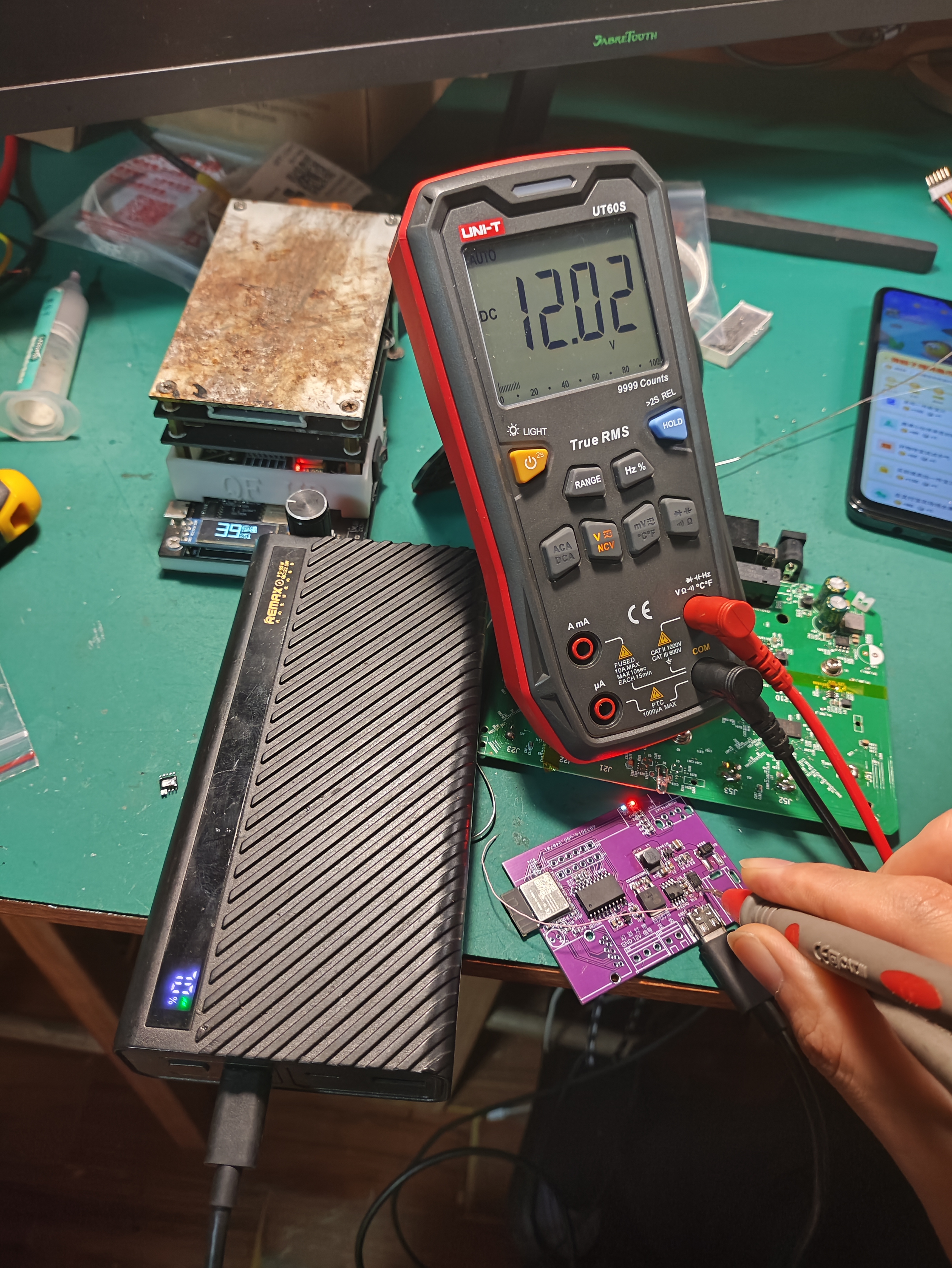
The board arrived,
the soldered

PD is working normally,
ESPHOME injected the soul, the firmware configuration

in the physical accessories of the device in HA

is configured, the hotspot password is hlhkhlhk, the API password to connect to HA is 7758258, let 's leave
it like this for now.
ESPHOME configuration file.yaml
desk-rgb.factory.bin
PDF_【Smart Home】ESPHOME Welded Exhaust Fan and Desktop Ambient Light Controller (Frankenstein's Monster) .zip
Altium_【Smart Home】ESPHOME Welded Exhaust Fan and Desktop Ambient Light Controller (Frankenstein's Monster) .zip
PADS_【Smart Home】ESPHOME Welded Exhaust Fan and Desktop Ambient Light Controller (Frankenstein's Monster) .zip
BOM_【Smart Home】ESPHOME Welded Exhaust Fan and Desktop Ambient Light Controller (Frankenstein's Monster) .xlsx
93689
Arduino Nano Expansion Board
Arduino Nano Expansion Board: This multi-purpose expansion board is a sensor expansion board specifically designed for Nano boards.
The Arduino Nano expansion board is a multi-purpose expansion board specifically designed for Nano boards.
Simply solder the headers on both sides of the Nano board and plug it into this expansion board. This solves the wiring mess when connecting multiple sensors on a Nano board, making it a powerful tool for your development projects. Features
include: 1. Exposing all digital and analog I/O ports, each with standard positive and negative power connectors;
2. Exposing the I/O pins on the motherboard for easy communication with I/O devices;
3. Adding a DC power supply interface. The USB ports on this board
only provide 50mA of power, which is
insufficient . The DC power supply interface provides an external power source to ensure stable device operation;
4. Providing VCC power switching, allowing you to switch all VCC power supplies to 3.3V or 5V;
5. Onboard test LEDs and test buttons for easy board testing.
PDF_arduino nano expansion board.zip
Altium_arduino nano expansion board.zip
PADS_arduino nano expansion board.zip
BOM_arduino nano expansion board.xlsx
93690
51 Multifunctional Timer Development Board
The 89c52 development board can detect temperature and humidity, and features a countdown timer and calendar, making it suitable for beginners learning projects.
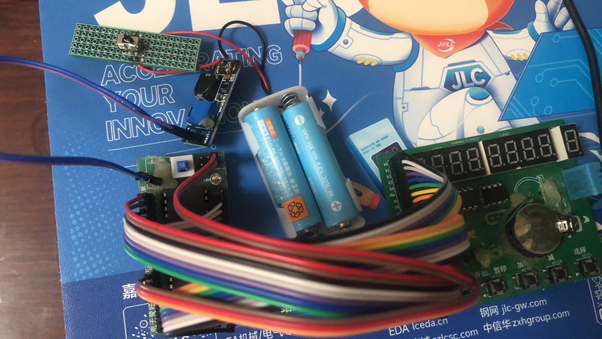
This does not include the microcontroller and minimum system! I am currently designing the complete development board. I have connected the minimum system board, battery box, and boost module
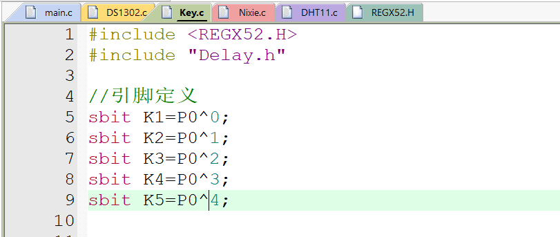
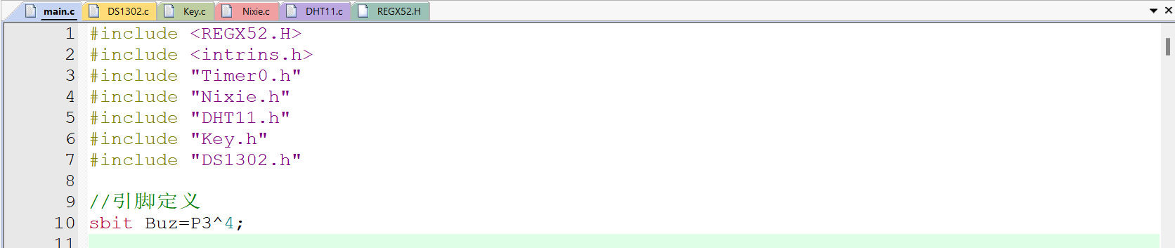
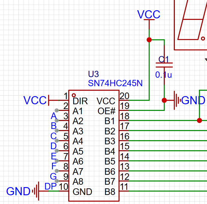
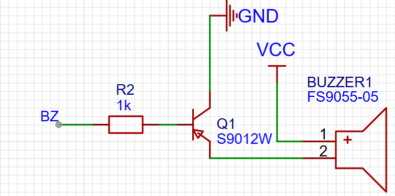
. The microcontroller can be freely replaced. Some library functions are from Jiangxie Technology on Bilibili. I recommend watching his 51 tutorial, which is very detailed. 51 Microcontroller Introductory Tutorial - 2020 Edition. The entire program is hand-typed from scratch. I am a second-year junior high school student. This is a work from two years ago. Now I am open-sourcing it and asking for a fee. This is my first time making one, and many packages were drawn incorrectly (now corrected), and many lines were missing. The system uses automatic routing, which may have some minor issues, but it doesn't affect usability. The schematic and PCB were poorly drawn at the time, and I'm too lazy to fix them. Functions: [Mode Key] Switches between the following modes in sequence: 1. Automatic temperature and humidity display; 2. Countdown: [Start/Pause Key] Starts/pauses the countdown; [Select Key] Resets; 3. Clock: Year, month , day, weekday, hour, minute, and second alternately displayed, saves settings after power failure ; [Start/Pause Key] Enters/exits setting mode, the date to be set flashes; [Increase Key] [Decrease Key] Sets the data (the program has an out-of-bounds detection, e.g., seconds can only be set from 0 to 59); [Select Key] Sets the next data (e.g., when setting the year, press to set the month), the order is year-month-day-hour-minute-second-weekday, default is 24-hour format; 4. Countdown: [Select Key] Starts setting, press again to set the next data (e.g., when setting seconds, press to set the minute), the order is seconds-minute-hour-a fraction of a second; [Increase Key] [Decrease Key] Sets the data (the program has an out-of-bounds detection, e.g., seconds can only be set from 0 to 59). [Start/Pause Buttons] Start/Pause: After the countdown ends, the screen flashes and the buzzer sounds. Press any key (except [Mode]) to turn it off. II. If the buzzer is too loud, comment out lines 368, 382, 383, 400, and 401 in main.c. Pin definitions are in the .c file. III. Burning: The attachment contains source code and a HEX file. For specific instructions, please refer to Jiangxie Technology's 51 video on Bilibili. I used STC-ISP: USB to TTL: IV. Partial Code and Schematic Diagram 4.1 Simple Explanation of the Code: The corresponding module code has been encapsulated into corresponding library functions, modified based on Jiangxi University of Science and Technology's work, so it will not be explained here. It is recommended to watch his 51 video. The complete source code and hex file are in the attachment. Use KeyFlag as the mode flag. Use the switch statement in the main function to switch between different functions. Note: 1. I encountered a pitfall while writing the code. The single-bus communication of DHT11 is asynchronous, and there is strict control over the high and low level times. Therefore, when obtaining temperature and humidity, the timer for scanning the digital tube needs to be paused, which is also the reason for the flickering of the digital tube in temperature and humidity mode. The flickering of the digital tube is not due to the camera; in fact, it's visible to the human eye. A solution hasn't been found yet. 2. It seems to be due to excessive statements in the timing function, causing a 0.1-second timing cycle to execute every 89 milliseconds. A solution hasn't been found yet either. Most repetitive work is done in the timer interrupt function, avoiding excessive delay interrupts in the main function. 4.2 Simple explanation of the schematic : Because the GPIO output current of the 51 microcontroller is too small to drive the digital tube, a tri-state gate is added to light it up. The digital tube is 0.36 inches with a common anode. The 0.36-inch size is to allow the board to be used within a 10*10 area. The buzzer is a passive buzzer, driven by a transistor.


Final version of the program.rar
project.hex
Demo video.mp4
PDF_51 Multifunctional Timer Development Board.zip
Altium_51 Multifunction Timer Development Board.zip
PADS_51 Multifunction Timer Development Board.zip
BOM_51 Multifunctional Timer Development Board.xlsx
93693
electronic


 京公网安备 11010802033920号

 RM462-196-843-9624


