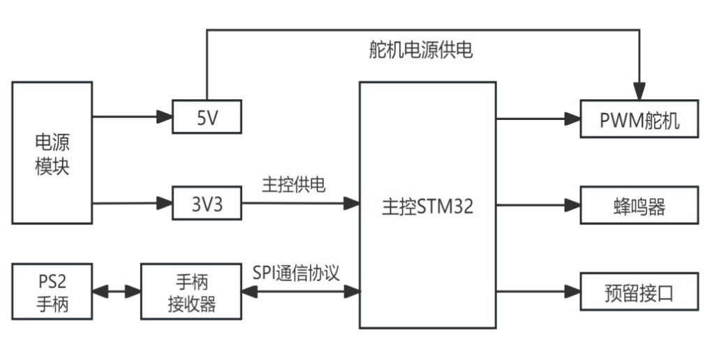
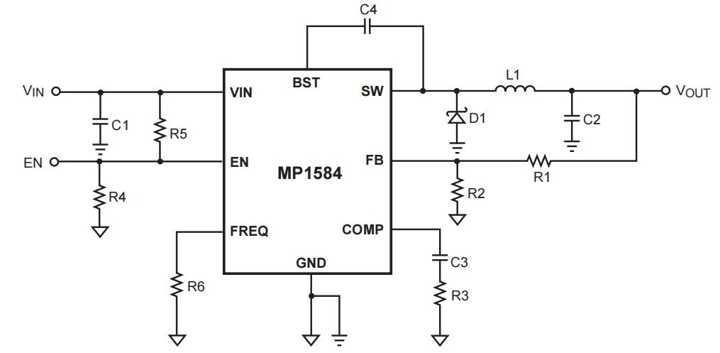
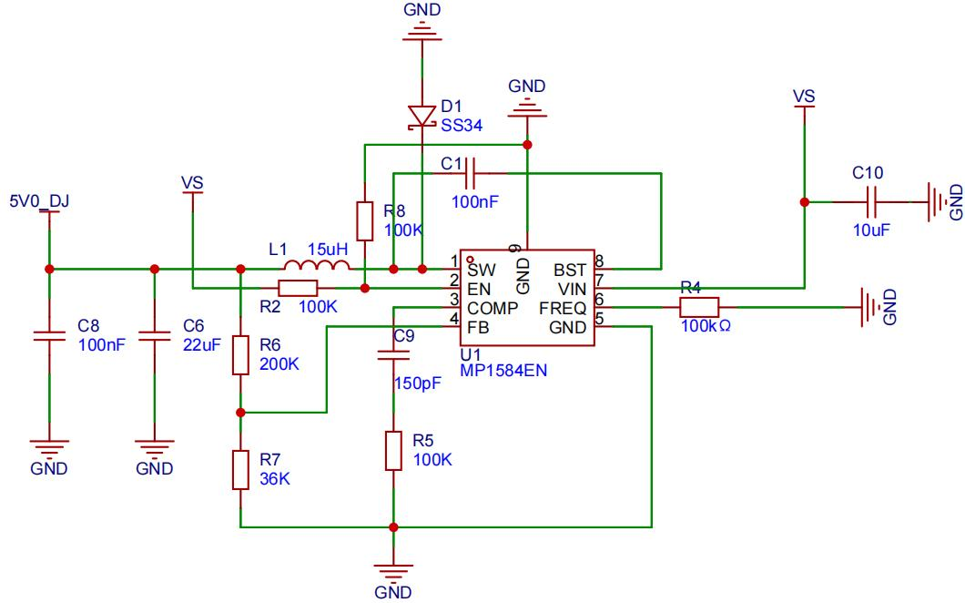
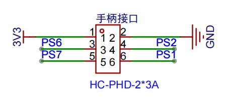
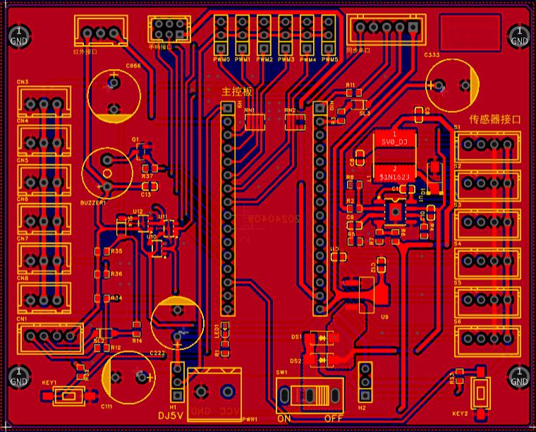
 , and the XC6206P332MR-G voltage regulator outputs a stable 3.3V as the main power supply for the driver chip. The other path provides external power through the baseboard's power adapter, which provides 8.4V. After conversion by the servo power chip, it outputs 5V as the main power supply for the servo motor. The schematic design is described below. The main control board uses the KPZ32 system control board, and the main control chip is STM32F103C8T6. This design uses a combination of the main control board and the base control board, which not only saves space but also facilitates troubleshooting. GPIO_PB13 enables SPI2 by multiplexing the SPI switch. The PWM servo pin configuration is: DJ0-PB3, DJ1-PB8, DJ2-PB9, DJ3-PB6, DJ4-PB7, DJ5-PB4. The buzzer pin configuration is: BEEP - PB5. The button pin configuration is: KEY1-PA8, KEY2-PA11. Two button channels are reserved. Detailed functions are executed according to a specific program. The baseboard schematic diagram includes the servo power interface, power module, voltage regulator circuit, handle interface, buzzer circuit, PWM servo interface, buzzer circuit, synchronous serial port interface, and power selection circuit. The baseboard's main circuitry is divided into two parts: one is the servo power supply circuit. In the initial design, when considering the filter capacitor, C10 was directly connected to the VIN input port via VS. Because the capacitor passes AC and blocks DC, and the baseboard uses an 8.4V/3A power adapter, the input voltage was also DC, causing the servo power supply to malfunction. In the previous V1.0 circuit board, C10 was directly connected in parallel to VIN using a flying wire. This bug was fixed in the V1.1 version of the baseboard design. The second part is the controller receiver interface. There was a problem with the component selection and PCB wiring sequence in V1.0. The base is packaged as a PHD 2*3 2.0mm male-female connector, but because the wiring sequence of the controller receiver interface and the baseboard interface is incorrect, a new double-female connector needs to be made. However, the PHD2.0 female connector requires an HC-PHD-T crimp terminal, not the usual 2.0mm crimp terminal. The MP1584 servo power module has an input voltage range of 4.5-28V and a nominal output current of 3A. In actual testing, it generated heat at 2A without any issues; any higher and the heat became excessive. Therefore, the PCB design should pay attention to heat dissipation on the exposed copper base. It is estimated that it can be used safely within 2A. The output voltage range is 0.8V~25V. The input voltage needs to be at least 3V higher than the output voltage for stability. The servo circuit schematic shows a PWM servo interface. The servo is connected to a six-pin header on the baseboard via DuPont wires. Each header has three pins: pin 1 connects to the servo signal, pin 2 connects to VCC_SERVERO (the servo's operating voltage), and pin 3 connects to GND. The six servo pins are controlled as follows: DJ0-PB3, DJ1-PB8, DJ2-PB9, DJ3-PB6, DJ4-PB7, and DJ5-PB4. VCC_SERVERO selects the servo power supply output voltage to 5V via a selection circuit. 3. PS2 Controller Interface: The controller interface has 6 ports. The controller receiver is directly fixed to the bottom of the base plate with screws and connected to the microcontroller using 6 silicone wires. The base uses HC-PHD-2*3A, which is more stable and greatly avoids poor contact caused by plugging and unplugging. Pin 1 connects to VCC to power the controller receiver. Pin 2 connects to GND to form a circuit. Pin 3 connects to PS6 on the base, and PS6 connects to PA14 of the main control chip, which is the CMD function of the controller receiver. Pin 4 connects to PS2, whose receiver function is ATT, and connects to PA13 of the main control chip. Pin 4 connects to PS7, whose receiver function is CLK, and connects to PA12 of the main control chip. Pin 6 connects to PS1, whose receiver function is DAT, and connects to PA15 of the main control chip. 4. Buzzer: The working principle of a self-excited buzzer is as follows: The DC power input is amplified and sampled by the oscillation system, and a sound signal is generated under the action of the resonant device. Its BEEP pin connects to the PB5 pin on the main control board, controlling the active buzzer's sound via a transistor. When the base is high, the transistor is cut off, and the buzzer does not sound; conversely, when the output is low, the buzzer sounds. PCB Design Notes : This section provides some PCB design instructions. For PCB layout, consider preventing reverse connections and using filter capacitors when distributing power supplies. Place them as close to the power input as possible. Avoid placing components below the servo power chip to prevent them from affecting heat dissipation. Place the PWM servo header in a location convenient for servo wiring. Keep normal signal routing as short as possible, avoiding sharp angles. If space is limited, use right angles at three-way junctions. Power lines should be at least 30mil. I used direct copper plating at the power input. Keep servo inductor routing as clean as possible, avoiding signal lines in the gaps below. The spacing between each component should be at least 10mil, and the copper plating spacing should be approximately 20mil. Software description code block: void loop_nled(void) { static u32 time_count=0; static u8 flag = 0; if(millis()-time_count > 1000) { time_count = millis(); if(flag) { nled_on(); } else { nled_off(); } flag= ~flag; } } // Serial port data reception and processing void loop_uart(void) { if(uart1_get_ok) { if(uart1_mode == 1) { // Command mode parse_group_cmd(uart_receive_buf); parse_cmd(uart_receive_buf); } else if(uart1_mode == 2) { // Single servo debugging parse_action(uart_receive_buf); } else if(uart1_mode == 3) { // Multi-servo debugging parse_action(uart_receive_buf);
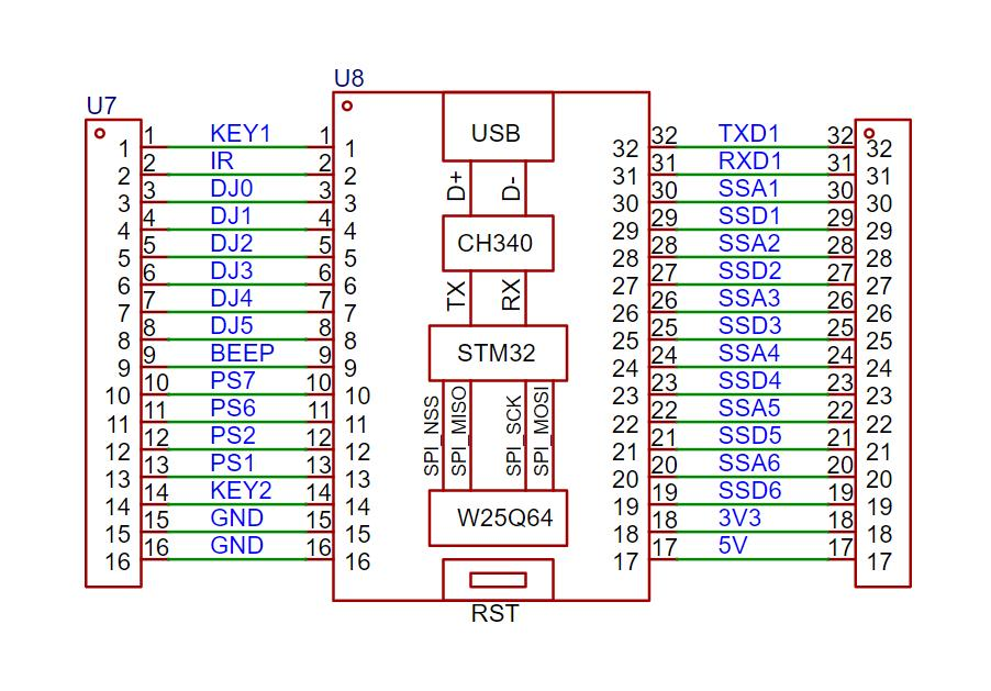


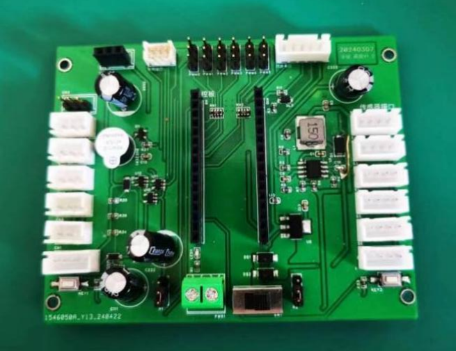 Physical display instructions
 Demonstration video
All reference designs on this site are sourced from major semiconductor manufacturers or collected online for learning and research. The copyright belongs to the semiconductor manufacturer or the original author. If you believe that the reference design of this site infringes upon your relevant rights and interests, please send us a rights notice. As a neutral platform service provider, we will take measures to delete the relevant content in accordance with relevant laws after receiving the relevant notice from the rights holder. Please send relevant notifications to email: bbs_service@eeworld.com.cn.
It is your responsibility to test the circuit yourself and determine its suitability for you. EEWorld will not be liable for direct, indirect, special, incidental, consequential or punitive damages arising from any cause or anything connected to any reference design used.
Supported by EEWorld Datasheet
EEWorld
subscription
account

EEWorld
service
account

Automotive
development
community

Robot
development
community

About Us Customer Service Contact Information Datasheet Sitemap LatestNews


Room 1530, 15th Floor, Building B,
No.18 Zhongguancun Street,
Haidian District,
Beijing, Postal Code: 100190
China
Telephone: 008610 8235 0740
 京公网安备 11010802033920号

 1N5948UR-1E3


