Project Description:
This is a Class A/B HiFi 2.0 amplifier. The input stage uses general-purpose operational amplifiers. The main components are the dual-channel audio amplifier circuit (with temperature compensation circuitry, which is crucial; improper adjustment will result in a Class A amplifier), speaker protection circuitry, and Bluetooth functionality. It is an
open- source project under
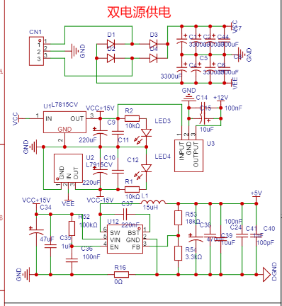
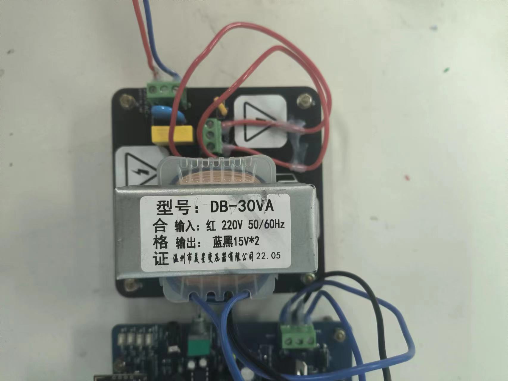
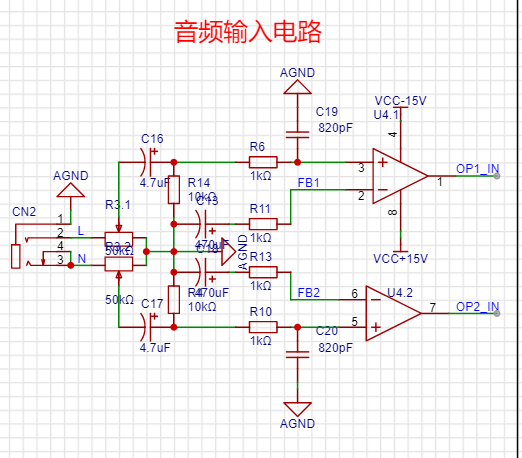
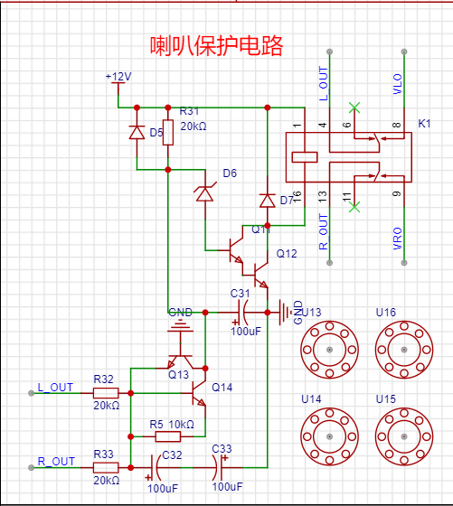
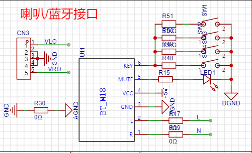
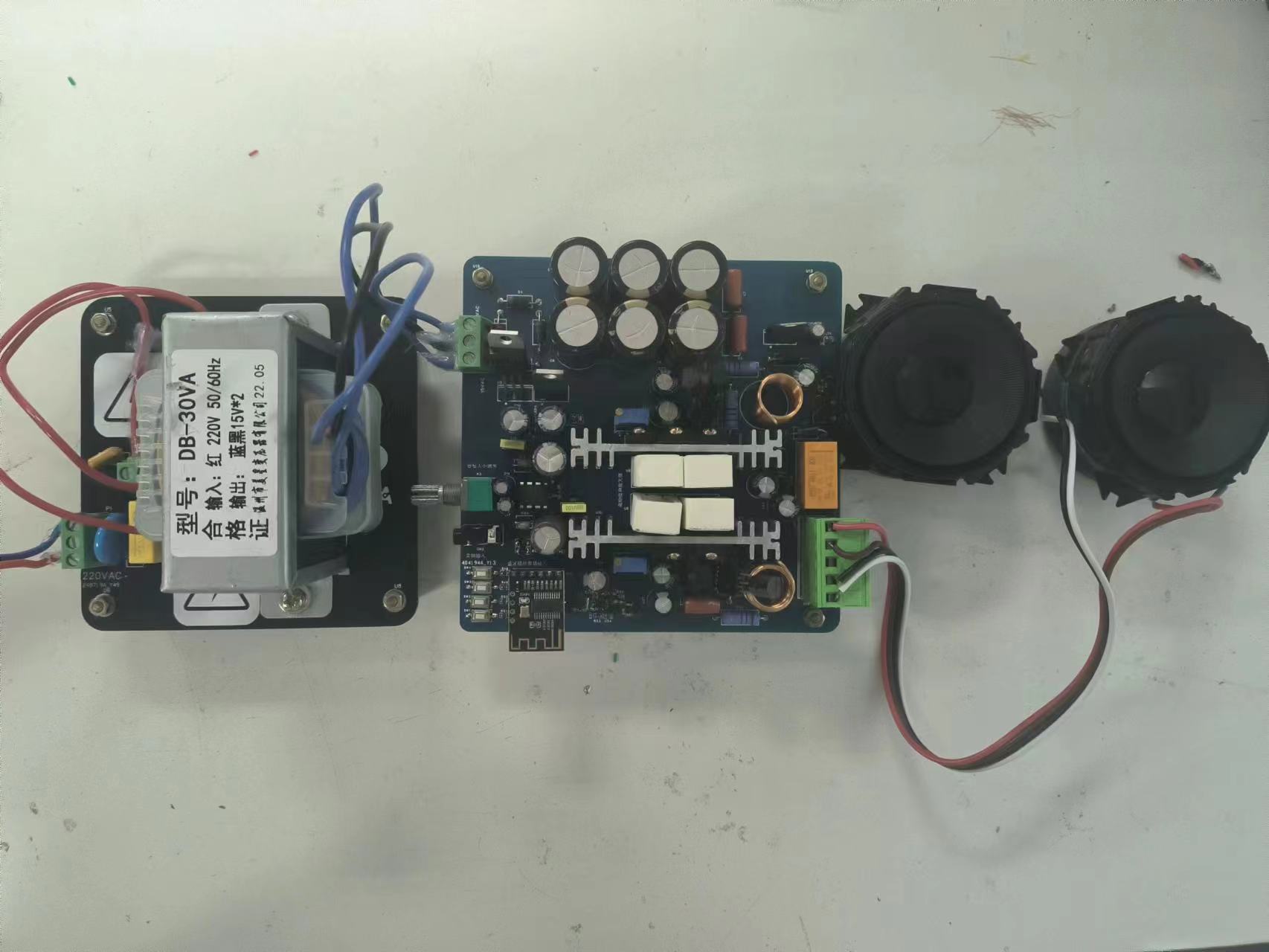
GPL 3.0 . This project is partially original and is being publicly released for the first time; it has not won any awards. Project Progress : The schematic and PCB layout are complete, and the physical prototype has been verified. Design Principles : This project consists of five main parts: 1. Power Supply: Implemented using an isolated toroidal transformer and several LDOs for positive and negative power supply circuits. The Bluetooth module uses a DC-DC converter (though LDOs are preferable for less interference). See the physical prototype below . 2. Input Stage: Implemented using general-purpose operational amplifiers. An 8-pin connector will be soldered in later to test operational amplifiers from different manufacturers and compare their performance. The audio input incorporates a frequency selection circuit, based on the human ear's audible frequency range of 20Hz~200000Hz, with f = 1/2πRC (see schematic for specific calculations). This extends downwards to approximately 5Hz and upwards by about ten times (25000Hz), essentially acting as a low-pass and high-pass filter. 3. Left and Right Channel Amplification Circuit (with Temperature Compensation): This circuit features two stages of amplification: one for voltage and one for current. A VBE multiplier circuit (temperature compensation) is added, along with negative feedback to ensure a more stable Q-point for the transistors. A Thiele network and a Joubert network are also included to absorb high-frequency spikes, prevent high-frequency self-oscillation, and provide capacitive and inductive compensation. 4. Speaker Protection Circuit: A power-on delay start-up circuit is added to the speaker to prevent damage from power-on shocks and DC components. 5. Bluetooth: This is a general-purpose Bluetooth module with a 0-ohm resistor for output isolation. Software Description: Implemented using analog circuitry; no software is required. Design Considerations for Physical Demonstration : 1. Before debugging, ensure the electrolytic capacitors are not reversed, otherwise the explosion sound will be quite loud. During actual debugging, many transistors in the two-stage amplification were damaged. The voltage of the VBE multiplier circuit was not properly adjusted, and the ones purchased from Taobao were also defective. One 7819 transistor was also broken, which was discovered through infrared thermal imaging (debugging is difficult without the right tools). I specifically soldered a socket for the transistors for easy insertion and replacement. 2. Pay attention to the temperature compensation of the VBE multiplier circuit. The three transistors should be arranged on a heatsink to ensure that their temperatures are as close as possible. 3. The voltage of the VBE multiplier circuit should be between 1.8V and 2.2V. 4. Due to the large current required for the last stage negative feedback, the resistance value should be between 0.1 and 0.33Ω (other values can be tried, but should not be too large). Use a high-power cement resistor. Other videos uploaded to bilibili: https://www.bilibili.com/video/BV1X34y1c7Du/?vd_source=53ac66056f5b386058aaf9d8b37d962e


 京公网安备 11010802033920号

 AFL27012SX-CH


