Physical Description: Hardware

:
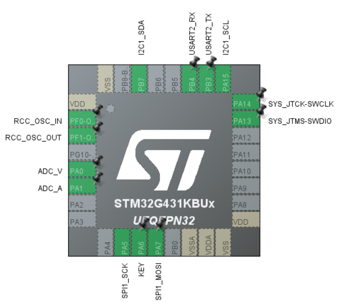
1. Main Controller: The main
controller is an STM32G431KBU3, which provides access to OLED, UART, and WS2812 (LED) for easy display and interaction
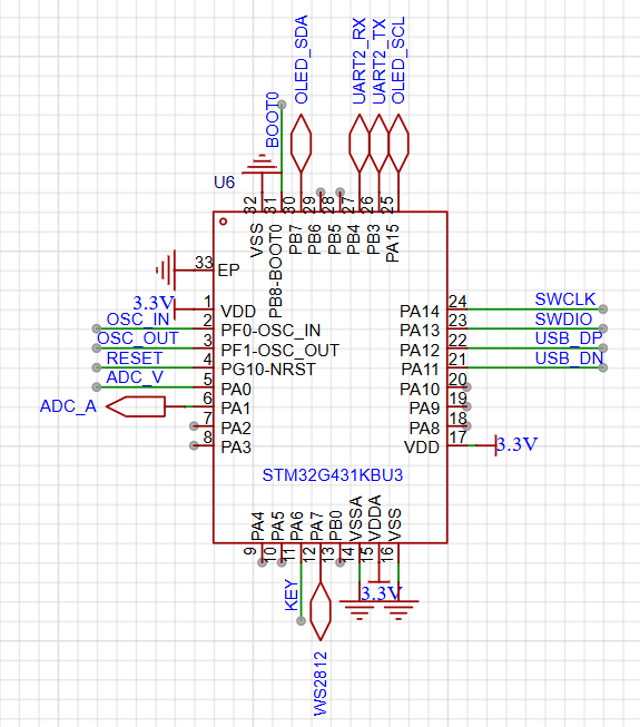
. 2. Current Detection:
The current detection circuit uses an ultra-precision current-sensing amplifier INA240. It differentially samples the voltage across the sampling resistor, amplifies it, and then filters it through an RC low-pass filter before feeding it to the microcontroller's ADC. The gain of the INA240 varies depending on the model; for example, the INA240A2 datasheet shows a gain of 20x for 50V/V.


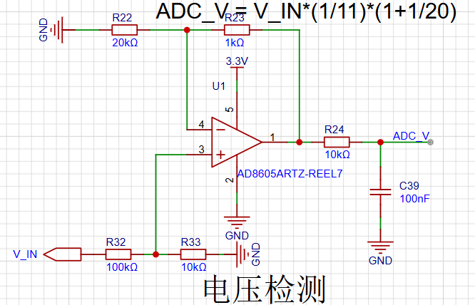
3. Voltage Detection:
Voltage detection uses a resistor divider, followed by voltage following using an AD8605 operational amplifier, and then filtering through an RC low-pass filter before feeding it to the microcontroller's ADC.
Software:
1. STM32CUBEMX Full Configuration:
2. ADC Configuration:
ADC1 and ADC2 are used to sample current and voltage respectively through separate channels. To improve sampling accuracy, the ADC is triggered by a timer using DMA. The configuration file and code will be attached.
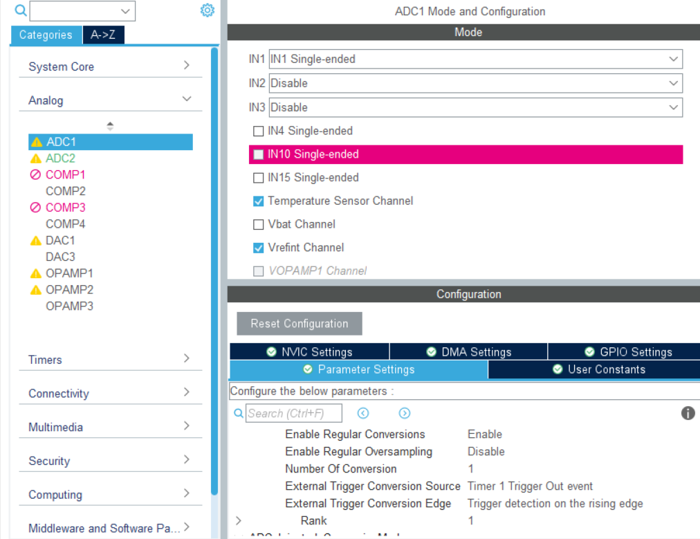
3. The specific
ADC code requires self-calibration to be enabled; otherwise, the sampling will be inaccurate.
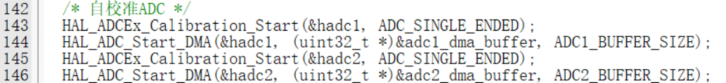
The actual voltage and current calculation formulas are given in the schematic diagram. The DC bias parameter of the current (1.662 in the figure below) needs to be slightly adjusted.

datasheet (INA240).pdf
program.zip
PDF_High-precision power meter based on STM32G431.zip
Altium - High-precision power meter based on STM32G431.zip
PADS_High-precision power meter based on STM32G431.zip
BOM_High-precision power meter based on STM32G431.xlsx
94174
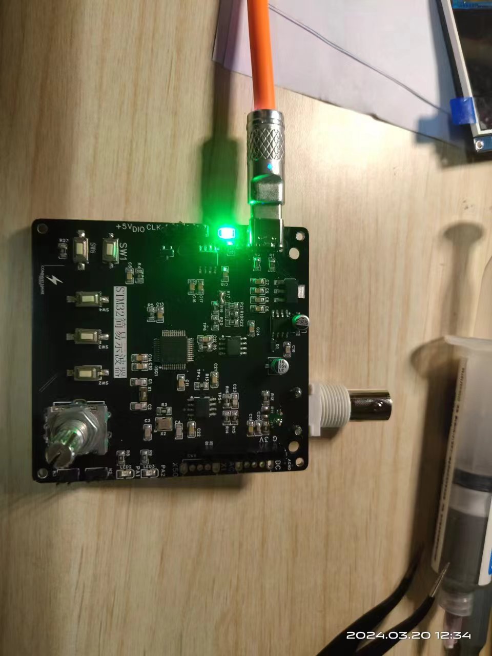
#Training Camp# Simple STM32 Oscilloscope
A Simple Digital Oscilloscope Based on STM32F103C8T6
This is a simple STM32 oscilloscope built following the JLCPCB training camp
. Circuit components: 1.
STM32 minimum system, integrating CH340 serial port download and Type-C reset one-key download function;
2. A 5V negative voltage generation circuit composed of XL7660 provides the negative power supply for the amplifier;
3. Input front-end amplification is performed by TL072IDR, amplifying the input signal and outputting a follower to the ADC and frequency capture circuit;
4. Frequency calculation is performed by an LM393 voltage comparator, which the MCU counts to obtain the input frequency;
5. Peripherals include two customizable LED indicators (current-limiting resistors can be selected according to LED color to prevent excessively dim or bright LEDs); three function buttons (PWM switch, duty cycle, frequency);
a rotary encoder (for waveform amplification and pause); and a PWM output interface;
6. Output display uses a 1.8-inch TFT full-color screen;
7. Includes an AC/DC coupling switch and an X1 and X50 multiplier switch, with multiplier switching obtained by resistor voltage division.
8. The circuit is powered by a 5V Type-C input, and the AMS1117-3V3 powers the MCU.
II. Code Section:
Based on the official example code, the hardware has been ported.
1. The ADC converts and prints the waveform point position. The external interrupt `EXTI` detects the button presses. A PWM waveform is output using the TM2 channel, and the TM3 channel captures the input frequency to obtain the frequency of the input waveform. (Some bugs in the code have not been fixed.)
2. Integrated CH340N serial port download, providing one-click Type-C serial port download and SWD download modes, which is convenient and fast. Only a Type-C cable capable of transmitting data is needed to download the program. (Compiled using KEIL5 MDK; FlyMCU is recommended for serial port download.)
3. Added a PWM output indicator LED, and another user-customizable one.
III. Shell:
A simple shell was made using SW (Steel Works) for easy one-handed grip, greatly improving portability. The grooved back reduces printing filament consumption and increases heat dissipation. The printing from JLCPCB is quite good. If the screws are not secure enough, a small amount of solder can be applied to the PCB positioning holes, and M2 screws can be used for fixing.
IV. Physical Product Demonstration:

Part 1.STL
c6fbfa027532a87be60fcc224d556d15.mp4
Simple Oscilloscope STM32 Version.zip
BH-F103.hex
PDF_#Training Camp#STM32 Simple Oscilloscope.zip
Altium_#Training Camp#STM32 Simple Oscilloscope.zip
PADS_#Training Camp#STM32 Simple Oscilloscope.zip
BOM_#Training Camp#STM32 Simple Oscilloscope.xlsx
94175
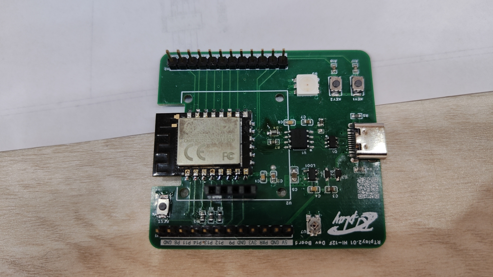
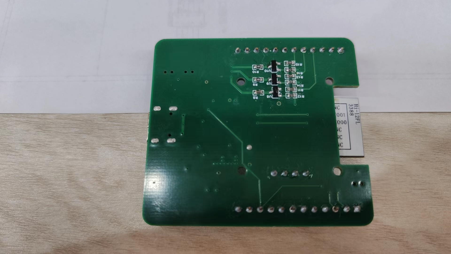
[HI-12F] Development board based on the Ai-Thinker hi-12f module
The development board based on the Anxinke hi-12f module integrates two buttons, a tri-color LED, a sliding rheostat, and can be connected to an external 0.96-inch LCD screen.
This development board, based on the Anxinke hi-12f module, integrates two buttons, a tri-color LED, and a sliding rheostat. It can connect to an external 0.96-inch LCD screen. ( The tutorial in
the CSDN blog post
"Hi3861 OpenHarmony Embedded Application Introduction - HarmonyOS Development Environment Setup"
will be gradually improved.)
PDF_【HI-12F】Development board based on Aisinco hi-12f module.zip
Altium_【HI-12F】Development board based on Aisinco hi-12f module.zip
PADS_【HI-12F】Development board based on Aisinco hi-12f module.zip
BOM_【HI-12F】Development board based on Aisinco hi-12f module.xlsx
94176
Summer mini fan
Speed-adjusting fan based on FM5012D chip
This product uses the FM5012D as the main control chip. This chip has two LED driver ports; the button port can simultaneously drive LEDs as a status indicator for the fan being on, and the LEDR port drives an LED indicating the charging status. The FM5012D features multiple protection designs, including overcurrent protection, soft-start protection, input overvoltage protection, output short-circuit protection, and chip temperature protection. The chip ports also incorporate high-performance ESD protection circuitry, giving this chip extremely high reliability. It features three fan speed settings and uses a standard coreless motor, making it simple to manufacture.
WeChat_20240618180722.mp4
PDF_Summer Mini Fan.zip
Altium_Summer Mini Fan.zip
PADS_Summer Mini Fan.zip
BOM_Summer Mini Fan.xlsx
94177
electronic


 京公网安备 11010802033920号

 12266A-2VX408


