Source address: https://github.com/tanaes/whopping_Voron_mods/tree/main/pcb_klicky (PCB_KLICKY)
It's said that three magnets are more stable and have a larger PCB area, allowing for more components to be stored, hence this project.
Magnets: https://item.taobao.com/item.htm?_u=p2jk0vj0a7ad&id=564130787836&spm=a1z09.2.0.0.540b2e8dMfFrdb
Direct 6mm thickness 3 inner holes 2
screws: https://detail.tmall.com/item.htm?_u=p2jk0vj0194a&id=643310565481&spm=a1z09.2.0.0.16262e8dEh5N6N
M2X8 3mm
Zener Transistor: https://item.taobao.com/item.htm?_u=p2jk0vj0be85&id=643357241091&spm=a1z09.2.0.0.16262e8dEh5N6N
SOT23 package, 5V output voltage is sufficient.
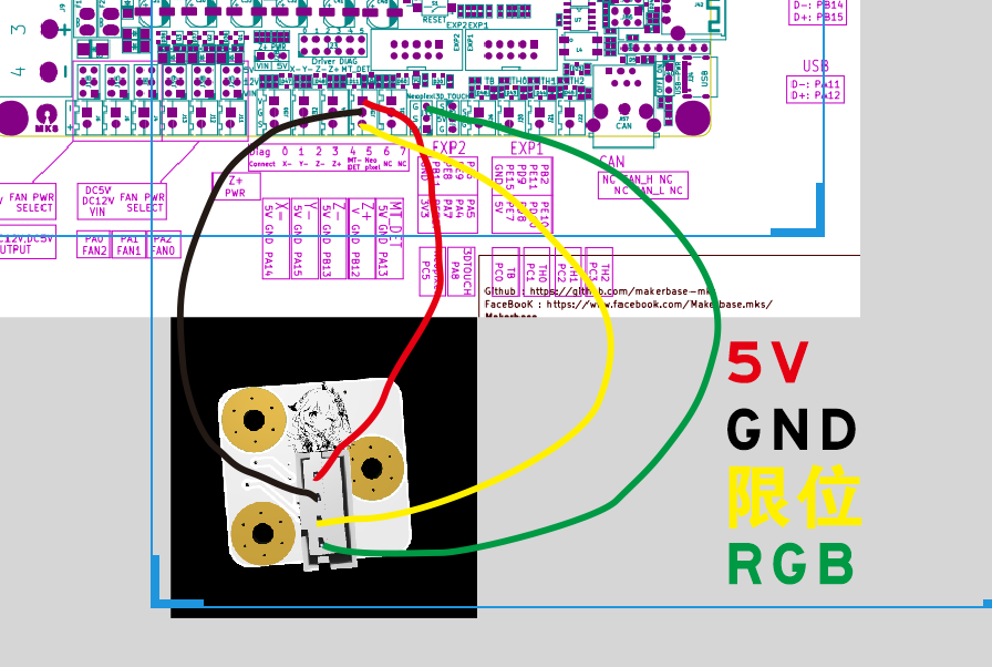
RGB LED: https://item.taobao.com/item.htm?_u=p2jk0vj003af&id=675654937526&spm=a1z09.2.0.0.16262e8dEh5N6N&skuId=4860297433766
The 5050 size and pin definitions are the same.
On the PCB, O represents normally open and I represents normally closed. For normally lit and micro-switch triggered lighting, join
QQ group: 701827620 (this is just a regular 3D printed AC adapter (with many modems)).
Please indicate the open-source address when selling.


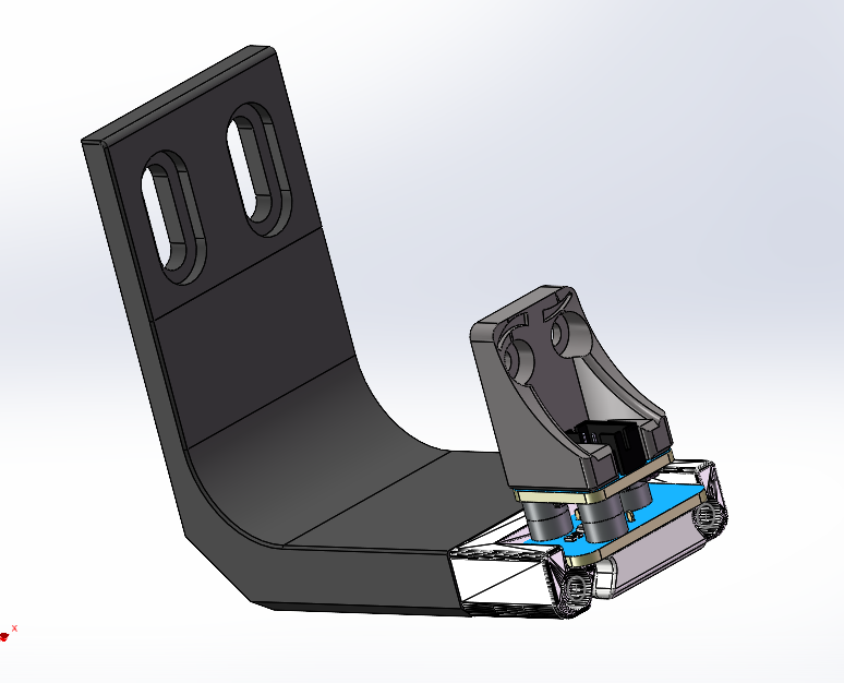
Three-magnet Klicky v1.5.STEP
V1.5 Welding Fixture.STEP
Bracket V1.6.zip
klicky Three Magnets V1.5 BOM Table.xlsx
PDF_klicky 3D Printer Magnetic Probe with 3 Magnets and RGB Version.zip
Altium_klicky 3D printer magnetic probe with 3 magnets and RGB version.zip
PADS_klicky 3D printer magnetic probe with 3 magnets and RGB version.zip
BOM_klicky 3D Printer Magnetic Probe with 3 Magnets and RGB Version.xlsx
95328
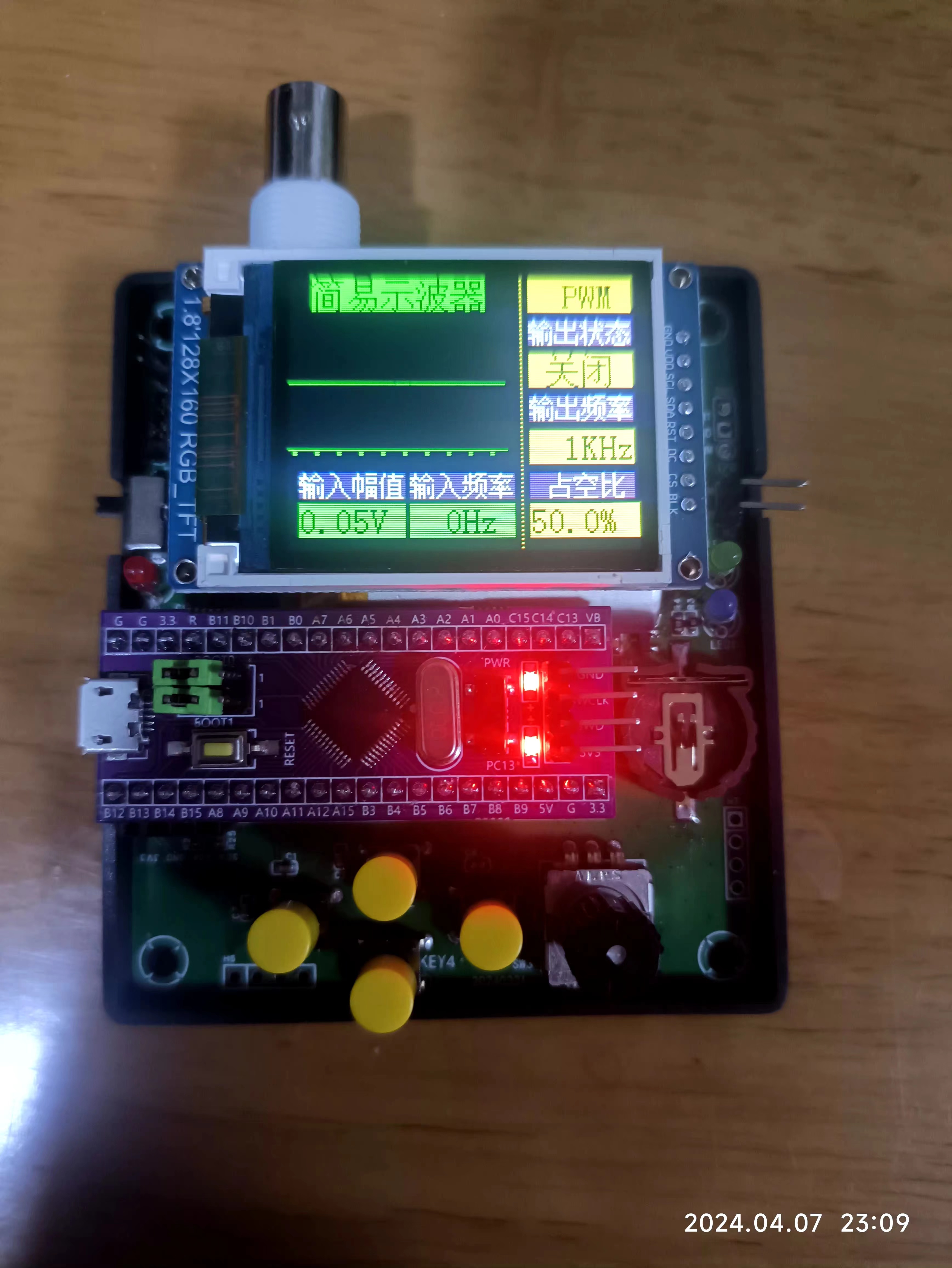
#Training Camp# Multifunctional Oscilloscope Based on STM32/GD32
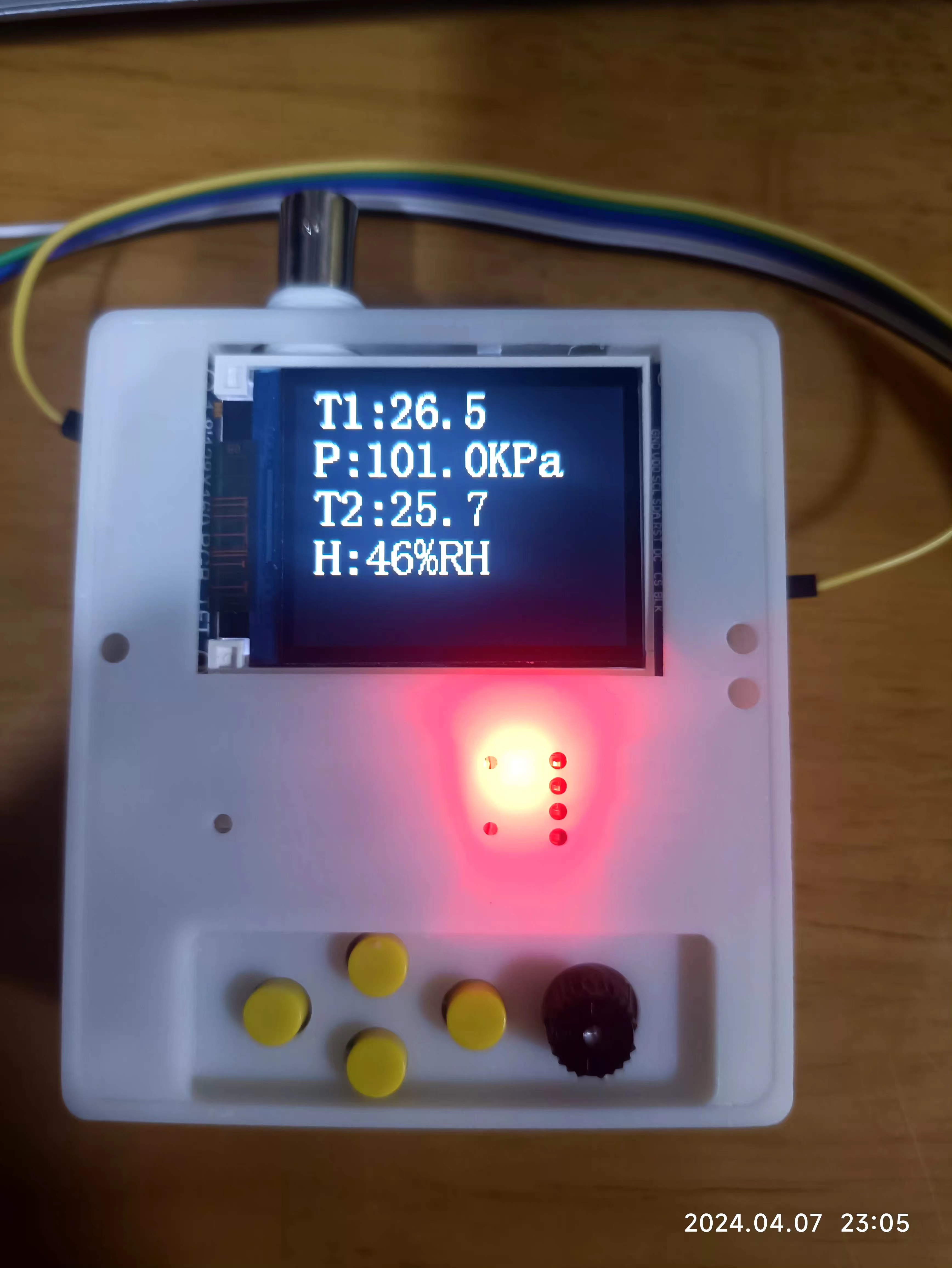
This multi-functional oscilloscope, based on the STM32/GD32 core board, integrates a simple oscilloscope, a desktop display (calendar/clock/alarm clock), environmental monitoring (temperature, humidity, and pressure), and a game (Tetris), and supports Type-C charging. It is compact and portable, and allows for easy switching between various modes with a single click.
Foreword:
I signed up for this training camp on a whim as soon as I saw it. I thought oscilloscopes were such high-end stuff, I had to learn them properly. Little did I know I'd get hooked so quickly, and there was no stopping me.
I made three versions of the board, starting with a replica, then struggling to find components and researching various alternatives, and finally, after verification, I succeeded on the first try! Thinking it would be a waste to just make a toy oscilloscope with this hardware,
I decided to add features. Adding features meant adjusting the pins (and rewriting the drivers – pure tears!). Sensors, RTC, buttons – I filled it up first.
For the second version, I added a casing, and it looked decent enough, but I thought there was still room for improvement, so I made two more casing versions. Luckily, the panel didn't make it in time, otherwise I would have had to make two more versions. In fact, it's practically two versions already.
I've been tinkering with the GD32, and then I got the urge to try the STM32. As of now (April 7th, 2024, 22:44:25), I'm still rushing to submit my assignment! I really don't want to miss the award! Then, I just got the STM32F103C8T6 working as an oscilloscope when I broke it. I urgently replaced it with the STM32F103C6T, but there's no time to do any more porting.
It's all the fault of the LCSC training camp! My costs! I'm hooked, and there's no way out.
In conclusion,
making a good product is really not easy; cherish every step. Thanks to this training camp for getting me into this rabbit hole, encountering all sorts of problems, and training myself in every way. Even now, I'm still typing out my assignment. Sigh, it's all tears.
My learning outcomes are as follows:
A - Based on GD32 core board:
1. Hardware design, material substitution, and verification are all OK.
2. Software implementation includes oscilloscope, sensor driver, clock/calendar/alarm clock, and a game (Tetris). Due to resource issues, it is not fully integrated yet, but individual tests are OK.
B - Based on STM32 core board
: 1. Hardware is the same as above
. 2. Software currently implements oscilloscope functionality; other functions are still being ported. Today is the last day, so I need to submit my assignment first.
C - 3D design:
1. Learning always comes at a price; I must print a physical prototype.
2. LCEDA is simple, easy to learn, and easy to use.
D - Panel design :
1. There are many videos on Bilibili; creative inspiration is needed.
2. Product thinking is required; design and experiment more.
Results presentation:
Show the effects of each. Two regrettable points: multiple functions could not be optimized and integrated together, and the panel design assignment was not submitted in time. Demo
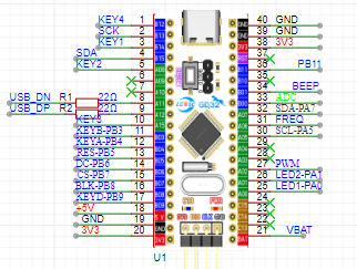
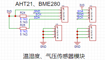
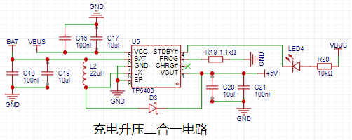
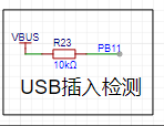
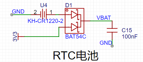
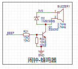
based on GD2 core board (Bilibili link) : https://www.bilibili.com/video/BV1gt421H7dW/?vd_source=24f1befd6441a33d7b240715cb07c7b5 Demo based on STM32 core board (Bilibili link) : https://www.bilibili.com/video/BV1QA4m1F77N/?vd_source=24f1befd6441a33d7b240715cb07c7b5 Hardware Design Description : This section focuses on the differences between the hardware design and the official design from the training camp. The official description of the similarities is still the best and most detailed; kudos to LCSC for this! MCU Design: To ensure compatibility with STM32 and GD32, some I/O adjustments were made, as shown below: 1- An additional button; 2- An additional USB detection I/O - PB1 3- Bring out PA9 and PA10 of the STM32; this can be used as a virtual serial port, utilizing the USB CDC function. 4- BEEP is used as the control pin for a passive buzzer. 5- The ADC is replaced with PB0, i.e., 8 channels. 6- Add one IIC channel for reading and writing sensors. 7- Bring out VBAT for use in the RTC circuit. 8- Leave an LSE pin for an external crystal oscillator to improve RTC accuracy. 9- A minor issue with the LED control pin replacement: the battery power detection I/O is not reserved. The sensor interface here features IIC interfaces for AHT21 and BMP280/BME280 for easy connection. It can be used as a smart home monitoring product. The lithium battery charging and discharging design uses the mature 5400 chip, as follows: The lithium battery charging interface uses microUSB, mainly for cost and USB pin convenience for STM32 development. The design is as follows: USB insertion detection confirms charging status. The voltage is unstable during charging; use during charging is not recommended. If using external power, it can be directly connected to the core board's USB interface. A 2.54mm pin header is provided for the lithium battery connection ; straight pins are soldered internally, and bent pins can be used if not connected. The RTC interface is designed to prevent the calendar from resetting due to power loss, and a CR1220 button battery is provided. A passive buzzer is included for convenient music playback, alarm reminders, etc. The lithium battery switch uses a physical shutdown circuit to control power consumption. Other differences : 1- All components have been changed to surface-mount materials, such as resistors, capacitors, and ICs . 2- The core IC has been replaced, as follows: 3- A button has been added , and the PCB design has been re-routed, so it will definitely be different from the official layout. However, the official layout is still referenced. The design uses LCEDA. It's free and open source. The casing design uses LCEDA. It's free and open source. Two versions were made; please refer to the design drawings and the previous physical photos for details. The panel design uses LCEDA. It's free and open source. Two versions were made, but they haven't been put into production yet; they are for reference only. The software design uses MDK, and the oscilloscope part references the official architecture and code. Thank you very much! One thing to note is that the interrupt line segmentation is the same for STM32 and GD32, so the interrupt functions and handling require special attention. Since the code isn't yet fully optimized, I won't post it here. Contact me if you need it. I'll share the code after I've improved the product. Now, you must submit your work!


Completed at 23:59:43 on April 7, 2024.
PDF_#Training Camp# Multifunctional Oscilloscope Based on STM32-GD32.zip
Altium_#Training Camp# Multifunctional Oscilloscope Based on STM32_GD32.zip
PADS_#Training Camp# Multifunctional Oscilloscope Based on STM32_GD32.zip
95329
#Training Camp# Simple Oscilloscope Based on GD32 - Simple Digital Oscilloscope
The LCSC training camp's simple oscilloscope based on the GD32 is a high-performance oscilloscope manufactured using a series of technologies including data acquisition, A/D conversion, and software programming.
This GD32-based digital oscilloscope operates on the principle of analog signal digitization and signal processing technology. When the signal under test is input to the oscilloscope, it is first sampled by an analog signal sampler, converting the analog signal into a digital signal. The higher the sampling frequency, the higher the digitization accuracy; therefore, the digital oscilloscope has higher resolution and more accurate waveform display.
The digitized signal is stored in memory and can be processed and analyzed by a processor. The oscilloscope's processor can perform various digital signal processing operations and can also transmit data to a computer for further processing and analysis via a computer interface.
The advantages of a digital oscilloscope lie in its high precision, high speed, and rich functionality. Digital oscilloscopes can acquire high-speed signals, a requirement that analog oscilloscopes cannot meet. Digital oscilloscopes can also perform more precise waveform analysis and processing, thus playing an important role in electronic design and debugging. This GD32-based digital oscilloscope also features programmability and automated testing capabilities, which can greatly improve testing efficiency and accuracy.
Video 1.mp4
video2.mp4
PDF_#Training Camp# Simple Oscilloscope Based on GD32 Simple Digital Oscilloscope.zip
Altium_#Training Camp# Simple Oscilloscope Based on GD32 Simple Digital Oscilloscope.zip
PADS_#Training Camp# Simple Oscilloscope Based on GD32 Simple Digital Oscilloscope.zip
BOM_#Training Camp# Simple Oscilloscope Based on GD32: Simple Digital Oscilloscope.xlsx
95330
#Training Camp#Simple_OSC
Simple Digital Oscilloscope
Design Background:
This training camp focuses on designing and building a simple digital oscilloscope, which is highly beneficial for developing comprehensive abilities. Participants in this digital oscilloscope project will not only learn microcontroller circuit design and development, but also signal conditioning circuit calculations, human-computer interaction design, and enclosure model design, integrating knowledge of analog circuits, microcontroller design, circuit and PCB design, and enclosure design.
Function Description:
Basic Functions:
1. Signal Measurement
: Range 1: Measures input signal amplitude from -1.6V to 5V.
1/50 Range: Measures input signal amplitude from -80V to 250V.
Note: Can test AC or DC.
2. Signal Frequency Measurement
: Measures signal frequencies up to 100kHz; tested successfully.
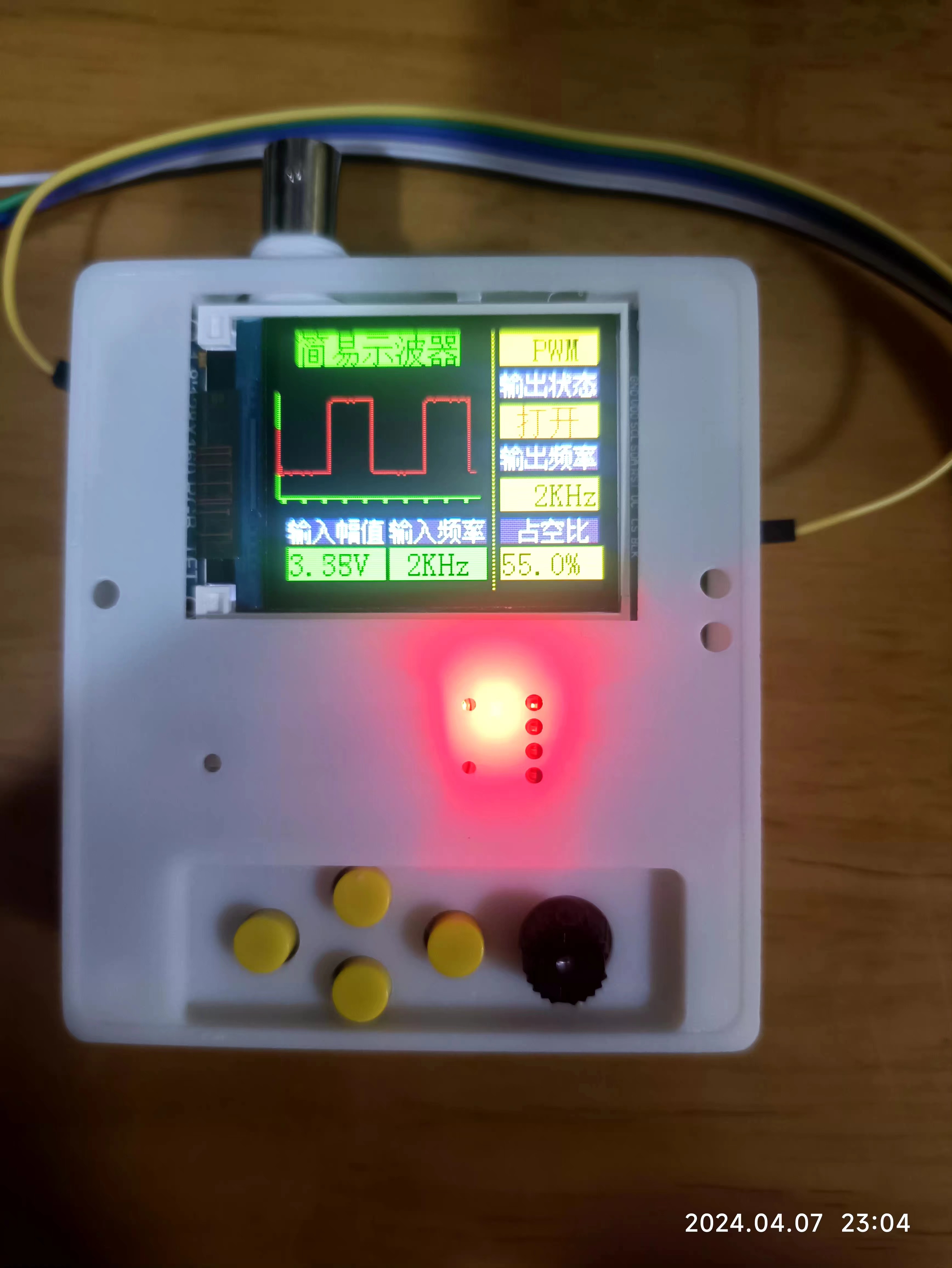
3. PWM Signal Output
: Outputs 1kHz, 2kHz, and 4kHz square wave signals (duty cycle adjustable). The power supply
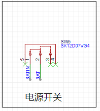
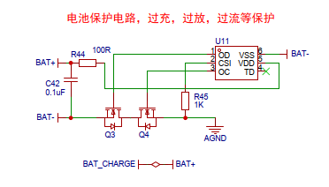
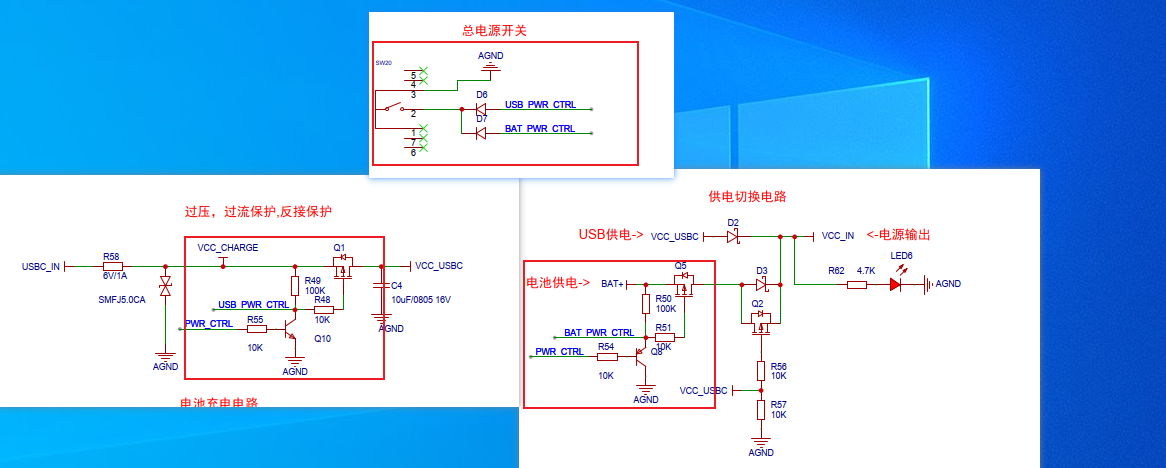
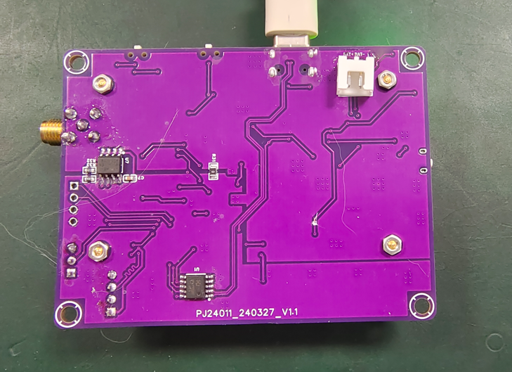
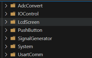
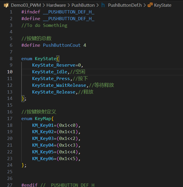
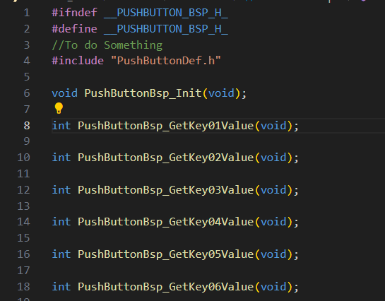
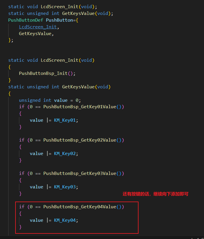
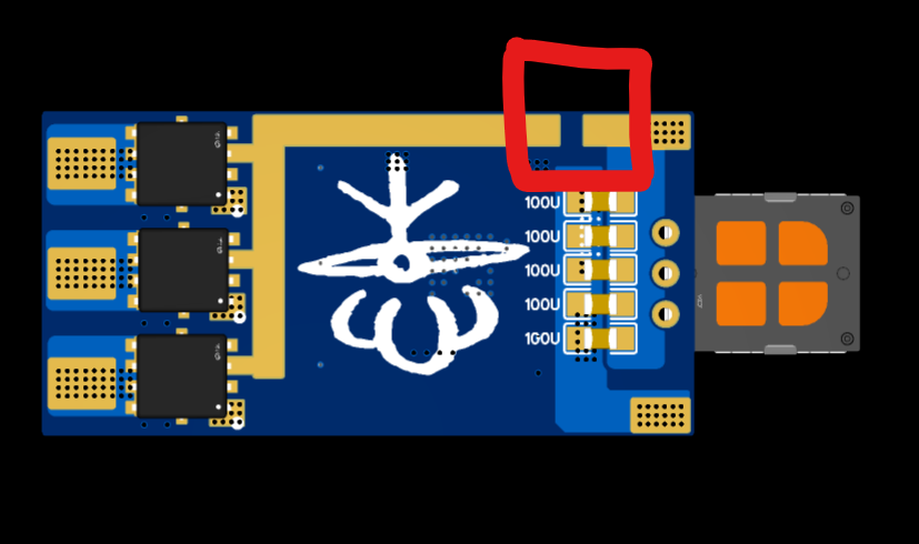
has been modified and innovated with the addition of overvoltage, overcurrent, and reverse connection protection. Battery protection, charging, and discharging circuits have also been added, making the oscilloscope more portable and eliminating anxiety about running out of power. A dual-power input (battery or external) switch has been added, allowing the oscilloscope to use battery power when there is no external input and external power when there is. A long-press power-on/power-off function has been added (the power-off function requires a jumper wire, which I forgot to draw at the time), meaning the microcontroller can control the power supply. A buck-boost circuit has been added to increase the external power input range and improve internal circuit stability. Battery voltage acquisition has been added (requires a jumper wire if the wiring is incorrect), allowing the oscilloscope to display the battery level and automatically shut down when the battery is low, in conjunction with the microcontroller. The PWM output has been expanded from one channel to two , and an EEPROM has been added to store user configuration information for loading upon next power-on. The screen has been upgraded from 2.0 inches to 2.4 inches with a resolution of 240*320, providing a better viewing experience. Other features include the removal of the coded switch and the replacement with five tactile buttons; retention of all functions of the GD32 core board, with all components being surface-mount and integrated onto a single board; and the replacement of the BNC connector with a smaller, more refined SMA connector. The schematic design includes output overvoltage, overcurrent, and reverse connection protection . R58 is a fuse, working in conjunction with a transient voltage suppressor diode to provide overcurrent and overvoltage protection. Q1 is a P-type transistor providing reverse connection protection. Battery charging (TP4065) and the familiar battery protection chip (DW01) are also common. The power supply switching circuit mainly consists of D2, D3, and Q2, but requires the external input voltage to be greater than the battery voltage. The button power on/off circuit is the part circled; the button directly controls the two MOSFETs Q1 and Q5, achieving the effect of power-on when pressed. After power is applied, the microcontroller indirectly controls the MOSFET through two transistors, Q8 (illustrated incorrectly here; it should be an NPN transistor like Q10) and Q10. When a button is pressed, the microcontroller takes over power control, allowing it to automatically power off. The circled area in the battery voltage acquisition diagram was drawn incorrectly and needs to be disconnected and connected to the battery's positive terminal with a jumper wire. This will be corrected in the next version. The voltage in the buck-boost circuit is not the standard 5V after the switching circuit; it may be lower. Furthermore, USB and other devices have significant ripple. Therefore, the voltage is directly buck-boosted to 7V before being converted to 5V and 3.3V by an LDO, making the subsequent circuits more stable and reliable. The subsequent storage circuitry is largely the same as the training project. Circuit Modification Instructions & Physical Demonstration: I've got a cat, so there's a lot of fur, please don't mind. I rewrote the program, but it's not completely finished. The program demonstration is shown below: Code Explanation: The code is written in modules, and the 2.4-inch screen driver has also been ported. The code structure is roughly the same. Which driver (button) code demonstration? 1. Button Definition 2. Button Hardware Driver Layer Header File: Source File : 3. Button Software Driver Layer Header File: Source File: 4. Call: Just call it directly. It's really convenient for future code reuse. If you have better ideas, we can discuss them together. Notes & Tips: To be updated later.


Demo03_PWM 2024-04-07 07-44-40.7z
PDF_#Training Camp#Simple_OSC.zip
Altium_#Training Camp#Simple_OSC.zip
PADS_#Training Camp#Simple_OSC.zip
BOM_#Training Camp#Simple_OSC.xlsx
95331
STC8H1K28 Main Control Potentiometer Speed Control Brushless ESC
STC8H1K28 Main Control Potentiometer Speed Control Brushless ESC
STC8H1K28 main controller brushless speed controller, STC official website example. Speed is controlled via potentiometer.
Original post address and firmware are as follows:
BLDC, Three-phase brushless DC motor driver - STC8/STC32 - no hall, 120,000 RPM, video explanation, Liang Gong example - BLDC/144MHz clock source PWM/45-channel PWM+3-channel CCP/7 groups of different cycle PWM/DAC - Guoxin Forum - STC Global 32-bit 8051 enthusiast mutual aid and exchange community - STC Global 32-bit 8051 enthusiast mutual aid and exchange community (stcaimcu.com).
The MOSFET used is Quanli AP3910GD 1P+1N 30V 36A. Approximately 1 RMB each on Taobao.
The VCC on the back is intentionally disconnected for soldering a self-resetting fuse during debugging to prevent board burnout.
Actual testing showed that two 18650 batteries, along with a self-wound Dyson motor, easily reached 5A. Suitable for DIY high-performance fans. It has not been destructively tested; it is recommended for use in applications under 3S or less.
PDF_STC8H1K28 Master Control Potentiometer Speed Regulator Brushless ESC.zip
Altium_STC8H1K28 master potentiometer speed control brushless ESC.zip
PADS_STC8H1K28 Master Control Potentiometer Speed Regulator Brushless ESC.zip
BOM_STC8H1K28 Main Control Potentiometer Brushless ESC for Speed Regulation.xlsx
95332
electronic


 京公网安备 11010802033920号

 S75NS-N


