I. Module Introduction
The project requires controlling the forward and reverse rotation of multiple brushed motors, while also needing to stop the motors quickly and limit their output current. The motor voltage is 24V. During the selection process, it was found that both the DRV8870 and AS4950 can achieve this function. Referring to the open-source four-channel brushed motor H-bridge driver board by FanHuaCloud, this dual-channel mini driver board was designed using the AS4950. Thanks to FanHuaCloud for their work.
II. Module Parameters
Input:
Number of Input Pins: 5-pin 2.54mm header, with one pin for the common terminal, one for the forward/reverse signal of channel 1, and one for the forward/reverse signal of channel 2.
Input Voltage: Compatible with 5V/3.3V input, supports PWM input for motor speed control.
Input Level: Due to the use of bidirectional optocouplers, it is compatible with both high and low level inputs. When COM is connected to the positive power supply, the input is low-level active. When COM is connected to the negative power supply, the input is high-level active.
Output:
Number of Output Pins: 6-pin 2.54mm header, with 2 power supply pins and 4 motor pins.
Power Supply Voltage: Connect to the motor's rated operating voltage. Although the AS4950 supports 8V~40V, the onboard 5V reference LDO only supports a maximum of 30V, so the maximum input voltage is limited to 30V. A voltage between 8-30V is recommended (DC24V was used in the project, and no abnormalities were observed during long-term operation).
Motor Type: Brushed DC motor.
Maximum Drive Current: Output current is limited to 2A.
Motor Operating Mode: The module defaults to pulling the AS4950 input pins high, so the motor is in a braking state when there is no input signal. To allow the motor to be in a free state, input both forward and reverse signals from the same channel simultaneously.
Motor Protection Function: Supports overcurrent/short circuit/undervoltage/overtemperature protection. If the output is short-circuited, the power supply must be reconnected to deactivate the protection.
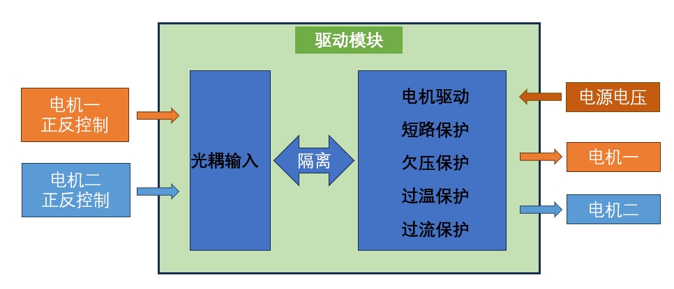
III. Module Block Diagram
IV. Circuit Details
Driver Chip Functional Block Diagram

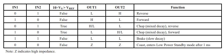
Driver Chip Logic Block Diagram The
isolated input section
uses a bidirectional optocoupler, with COM as the common terminal and a 560Ω current-limiting resistor, compatible with 3.3V and 5V inputs.
If the input signal is 24V, the 560Ω current-limiting resistor can be replaced with a 4.7kΩ/250mW surface-mount resistor, or a 4.7kΩ/100mW color-coded resistor can be connected in series in the input circuit.
PWM input is supported; COM is connected to the negative terminal, and the PWM output port is connected to the positive terminal.
The optocoupler output is pulled high by default through a 10kΩ resistor, so the motor driver chip is in braking mode by default. See the driver chip logic block diagram for details.

The motor driver
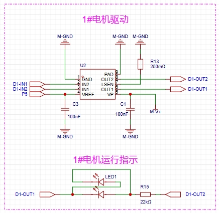
uses a 5V reference voltage, and a 250mΩ sampling resistor is used to limit the output current.
The current-limiting calculation formula is: I=(VREF/10)/R, where VREF is the reference voltage and R is the LSEN sampling resistor to ground. For example, if 5V is used as the reference voltage and 0.25Ω is used as the sampling resistor, the calculated I=5/10/0.25=2A.
Operation indication: A dual-color LED indicates the driver chip output.
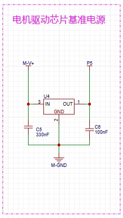
The LOD reference voltage
is an onboard 5V reference voltage used to provide the driver chip's logic power and current-limiting reference power.
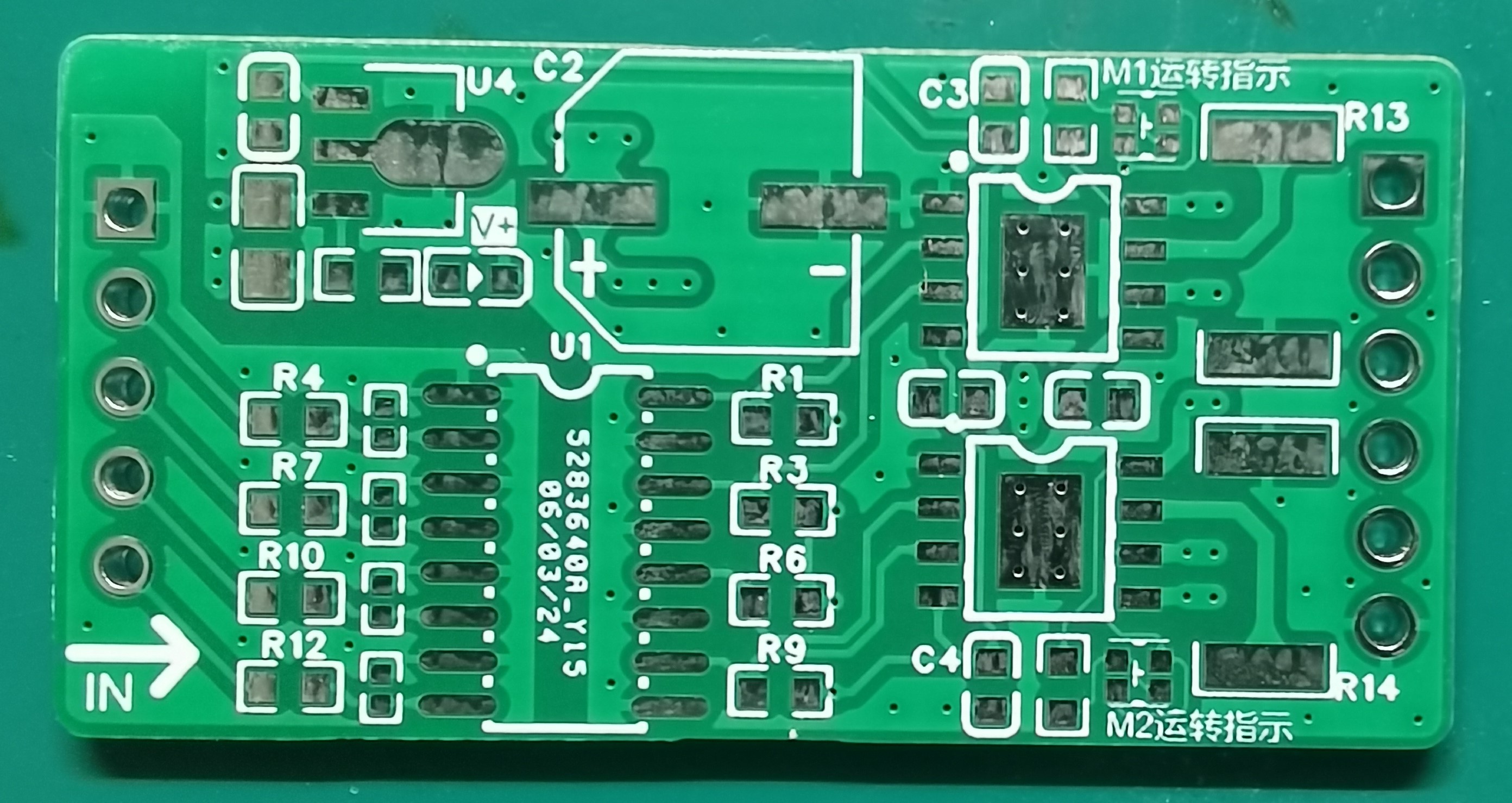
V. PCB Specifications
and Dimensions:
Dimensions: 40mm * 20mm
; Pin Spacing: 36mm;

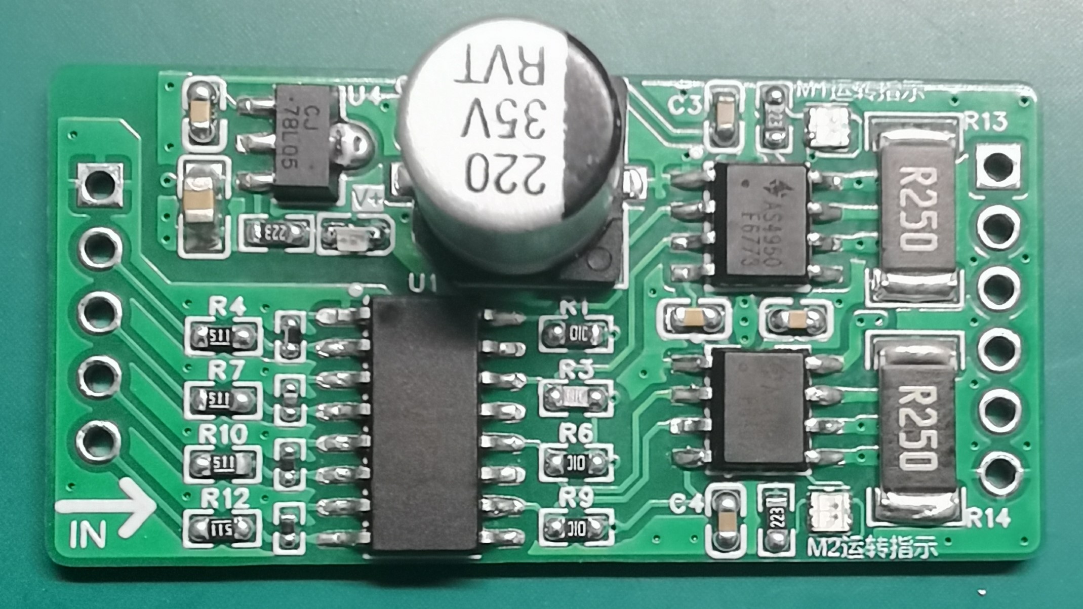
Main Components:
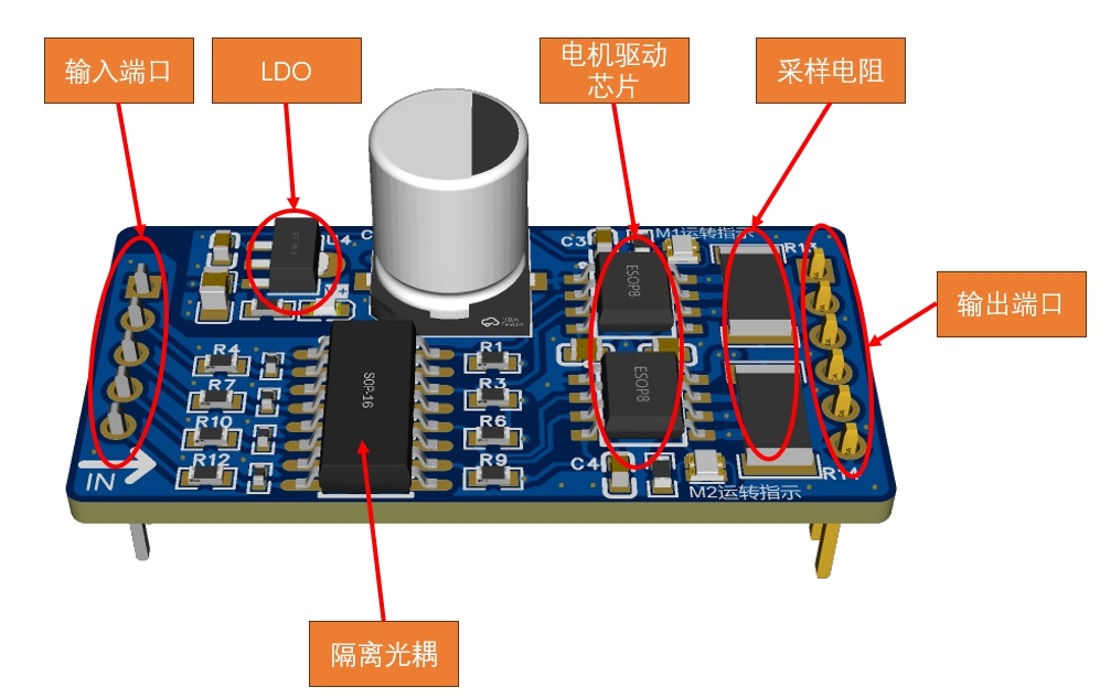

Wiring Method:
Input Terminals:
COM: Common terminal for optocoupler input;
M1+: Forward signal for motor 1;
M1-: Reverse signal for motor 1;
M2+: Forward signal for motor 2; M2-: Reverse signal for motor 2. Output Terminals: M-V+: Motor power positive
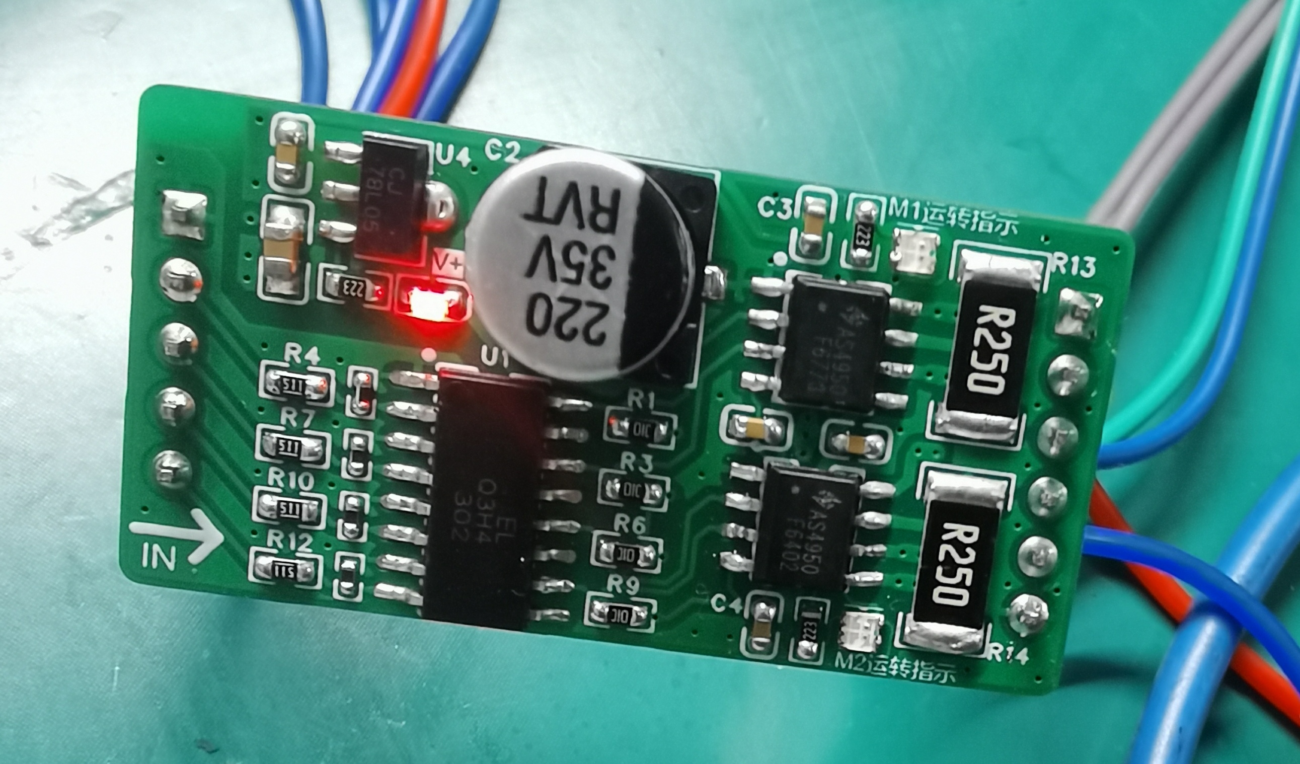
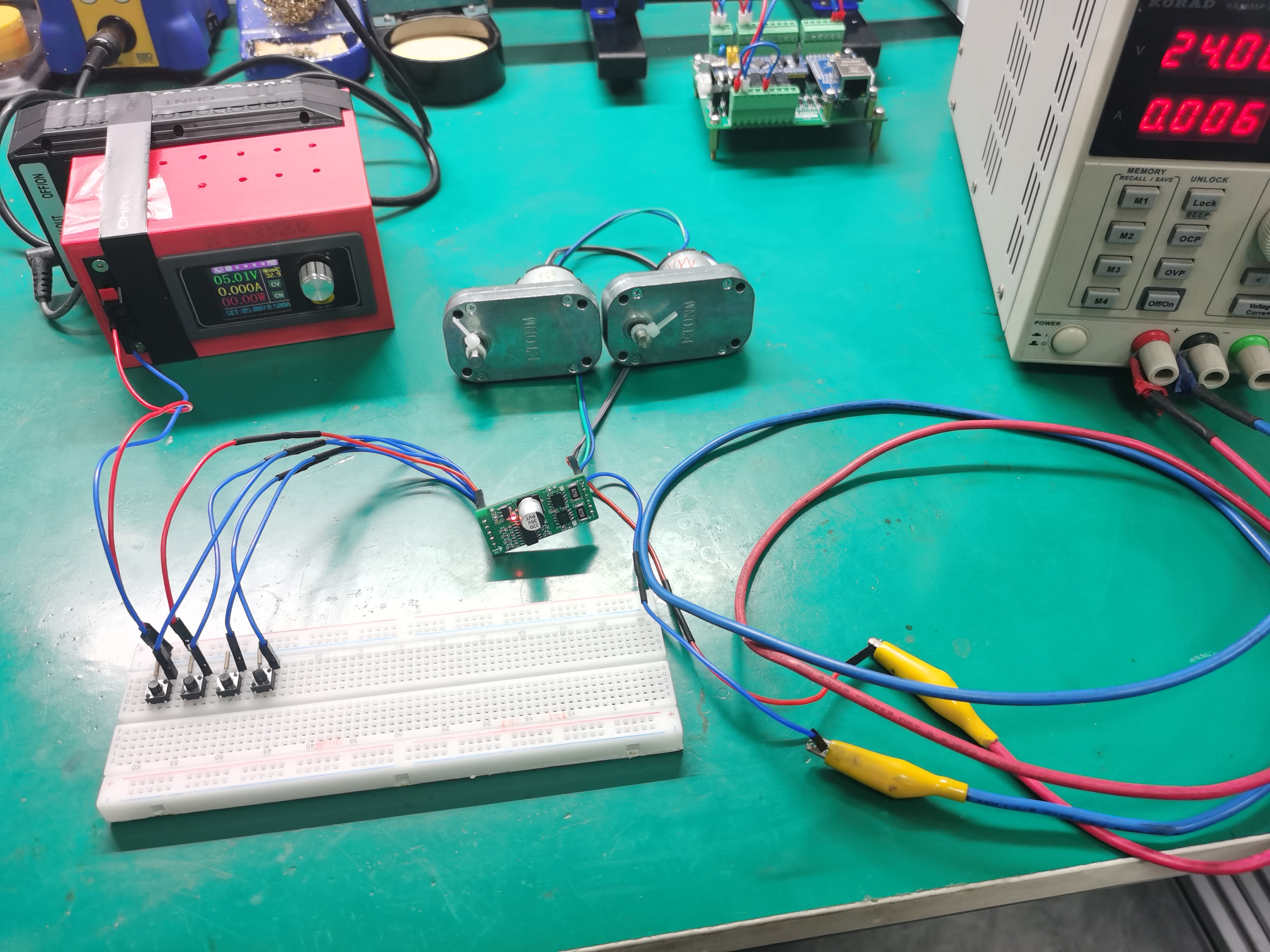
; M1-OUT2: Positive terminal for motor 1; M1-OUT1: Negative terminal for motor 1; M2-OUT2: Positive terminal for motor 2; M2 -OUT1: Negative terminal for motor 2; M-GND: Negative terminal for motor power. VI. Physical Demonstration: PCB coated with solder paste, soldered, and powered on for testing. VII . Precautions: Input voltage should be limited to a reasonable range. 5V/3.3V testing showed no abnormalities. For other excessively high voltages, the power of the current-limiting resistor needs to be considered. Do not connect the motor power supply positive and negative terminals incorrectly; incorrect connection may burn out the chip. When soldering yourself, ensure reliable soldering. 8. Demo Video Video Link: https://www.bilibili.com/video/BV1mZ421u7RU/?share_source=copy_web&vd_source=3bedf512bd1857b7727268e3c539acd7


 京公网安备 11010802033920号

 HSMZ-A100-T00J1


