 A. First is the minimum system of the single chip.
 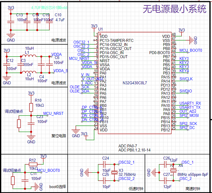 This is relatively standard; just follow the reference materials. It's worth mentioning that, to save costs, a reference power supply IC was not used; instead, a filter was added before connecting it to the ADC reference input. The BOOT0 boot partition selection and RST are only soldered with 0603 resistors, with external buttons attached. This allows for disassembly and adjustment after program debugging, improving the appearance.
 drops from 20V to approximately 0.5V, demonstrating excellent MCU protection. It has a sufficiently wide voltage tolerance and is fully compatible with QC3.0's 12V.
  programming, UART serial programming and SWD are introduced. SWD is recommended for one-click programming in Keil. UART requires downloading the National Technology download software. Furthermore, UART cannot be debugged.
 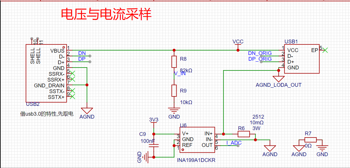 calculates power by collecting the input voltage and the current on the bus.
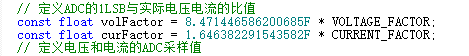
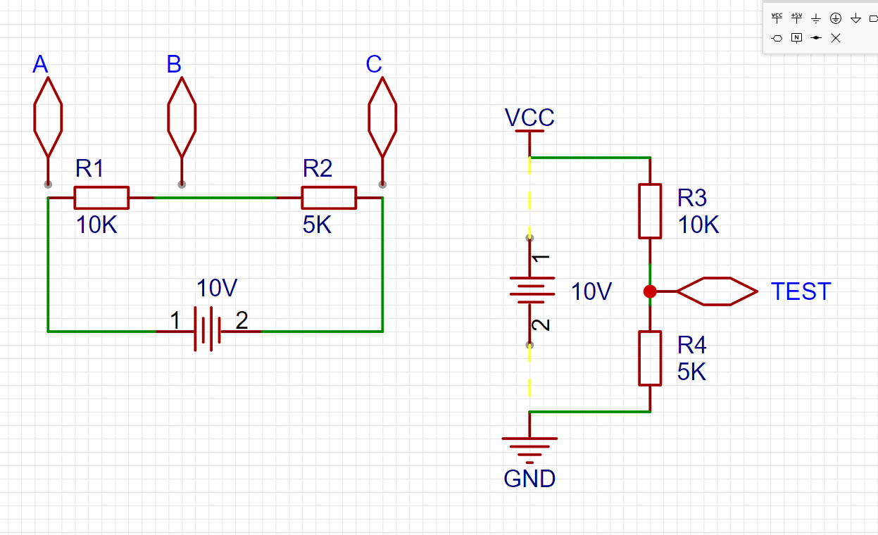 Using the voltage range of a multimeter, we can measure the voltage difference between any two points. Note that it's the voltage difference between two points. For example, in the above diagram, we would say that Uab voltage is 6.66V, and Ubc = 3.333V.
  as shown in the figure, the actual ADC sampling value is 679.
 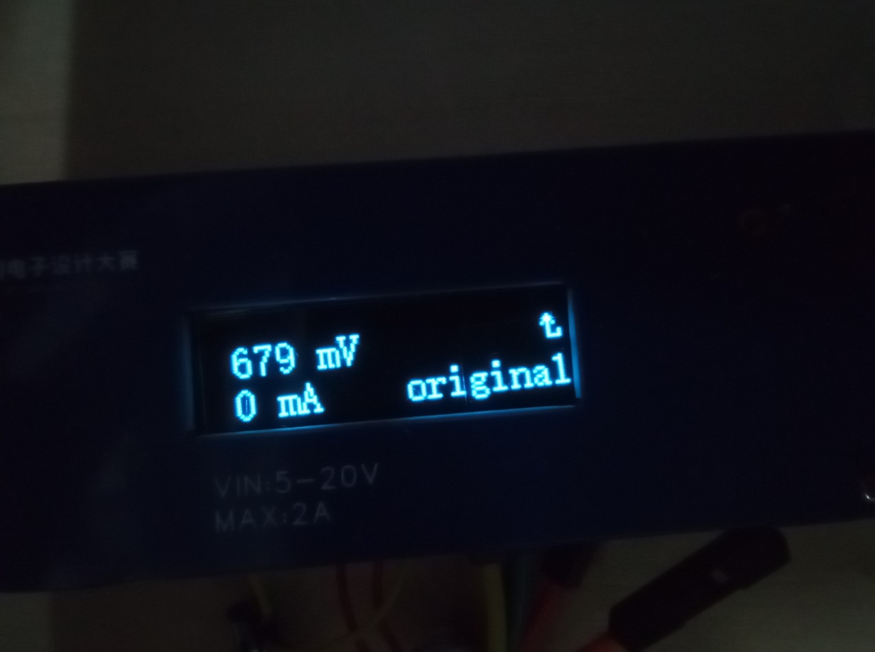 What does this ADC value mean?
 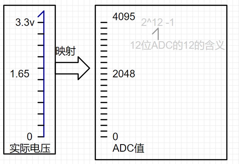 So, the ADC=679 comes from
  ADC=Utest/3.3 *4095= 679.
 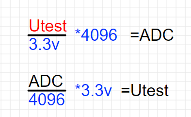 Utest=ADC ÷4096*3.3=0.547V.
  Next is current acquisition. Here, the INA199's 50x differential voltage amplification is used. "Differential mode" can be understood as the voltage measured by pressing the multimeter probes across a resistor.
 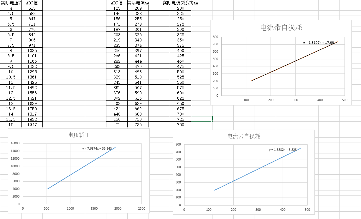 To correct the bias, I used an adjustable power supply coefficient correction. It's quite close to the theoretical calculation. (To achieve this, search for Excel fitting curves yourself.)
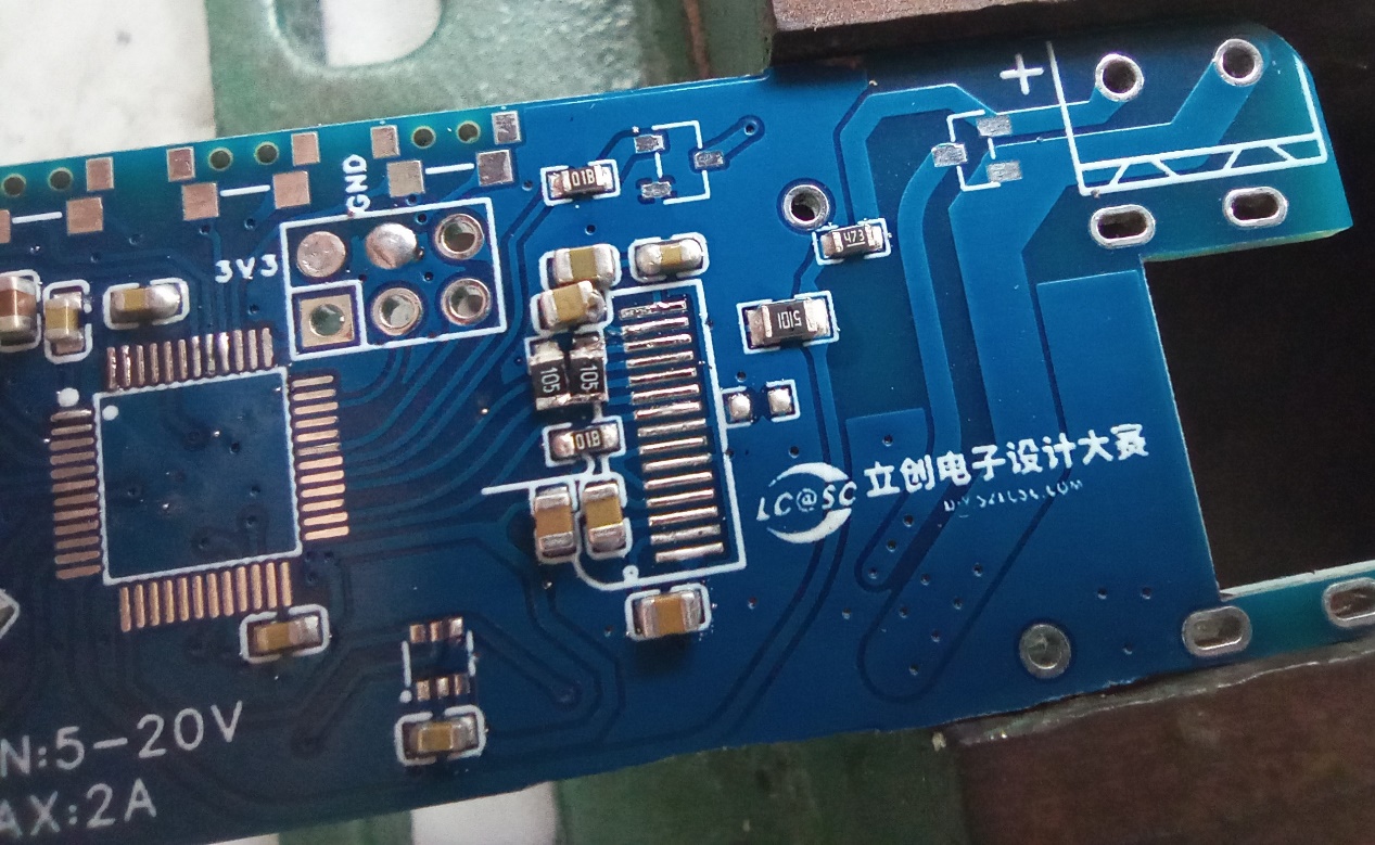
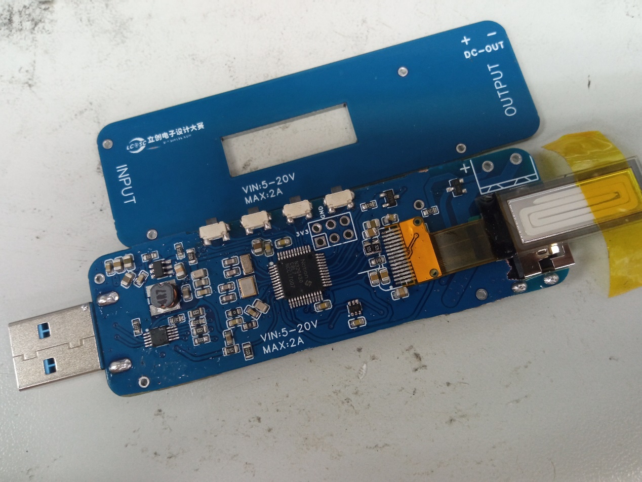
  . On the left is a USB 2.0 analog switch IC. Using a USB 3.0 male connector ensures the system powers on first and starts working, defaulting to USB 2.0 input/output. As you can see in the schematic, my positive and negative terminals don't match the IC; this is for easier routing in the physical PCB. The datasheet specifies rail-to-rail, which is why I dared to do it this way. Regarding the QC3.0 charging protocol, please search for information yourself.
  will be provided on Bilibili later .


All reference designs on this site are sourced from major semiconductor manufacturers or collected online for learning and research. The copyright belongs to the semiconductor manufacturer or the original author. If you believe that the reference design of this site infringes upon your relevant rights and interests, please send us a rights notice. As a neutral platform service provider, we will take measures to delete the relevant content in accordance with relevant laws after receiving the relevant notice from the rights holder. Please send relevant notifications to email: bbs_service@eeworld.com.cn.
It is your responsibility to test the circuit yourself and determine its suitability for you. EEWorld will not be liable for direct, indirect, special, incidental, consequential or punitive damages arising from any cause or anything connected to any reference design used.
Supported by EEWorld Datasheet
EEWorld
subscription
account

EEWorld
service
account

Automotive
development
community

Robot
development
community

About Us Customer Service Contact Information Datasheet Sitemap LatestNews


Room 1530, 15th Floor, Building B,
No.18 Zhongguancun Street,
Haidian District,
Beijing, Postal Code: 100190
China
Telephone: 008610 8235 0740
 京公网安备 11010802033920号

 M12543HHS


