The STM32F407VET6 core board comes with ST-LINK-V-2.1, is Raspberry Pi-sized, has a standard 40-pin connector, and uses the same screen connector as the Liangshanpai 148 RMB model.
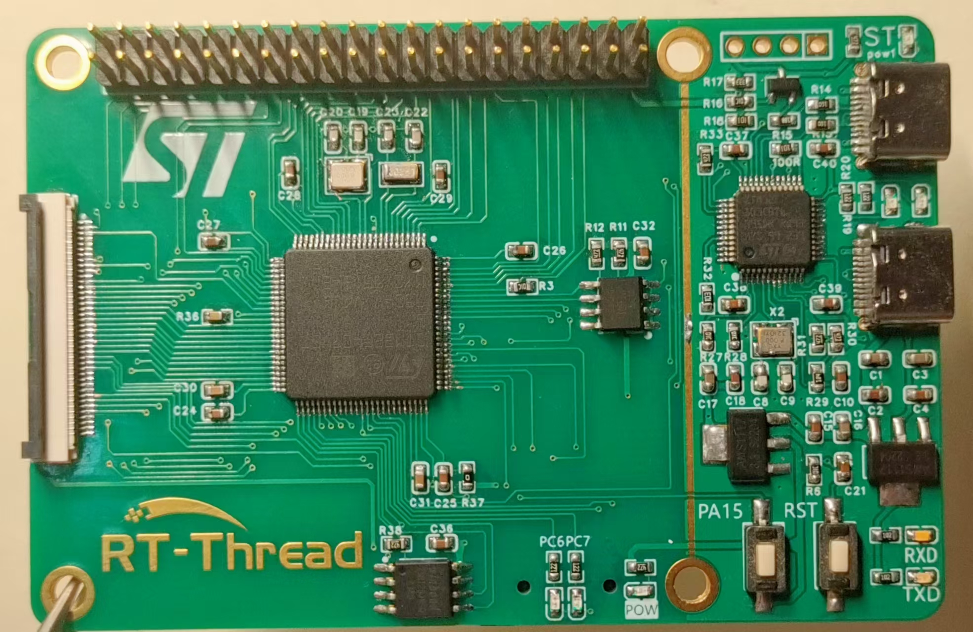
PDF_STM32F407-RT-THREAD Development Board.zip
Altium_STM32F407-RT-THREAD development board.zip
PADS_STM32F407-RT-THREAD development board.zip
BOM_STM32F407-RT-THREAD Development Board.xlsx
94564
Retro Industrial Style Clock with Glow Tubes—Based on ESP32
Based on the ESP32-wroom glow tube clock design, it uses inexpensive QS30 glow tube bulbs, keeping costs low. It features a wooden casing, integrated boost module, and network-connected automatic time synchronization.
This project has not yet been prototyped and verified; please proceed with caution!
A while ago, I was obsessed with retro industrial design. Seeing the neon tube clock design by the master OMNIXIE, I was instantly captivated and began studying the working principle of neon tubes. After three nights of intense study, I had an epiphany and began designing my own neon tube clock.
Neon tubes are considered rare antiques these days. I vaguely remember seeing one in the rural power station in my hometown when I was very young. The moment it automatically refreshes from 0 to 9 to prevent cathode poisoning is probably its most beautiful and cyberpunk moment.
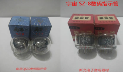
Struggling with my modest budget, I chose a relatively inexpensive neon tube this time: the QS30-1 neon tube, made in Nanchang. The SZ-8 tube from Universe can also be used. The price is relatively cheaper than other stock, around 35 RMB each. Other tubes like the IN-18 are overpriced on Xianyu (a second-hand marketplace) because of the designs by these masters, and they immediately talk about nostalgia and retro style; if you say it's 30-year-old stock, they'll get angry.
For the main controller, the inexpensive and reliable ESP32 is the best choice since network-connected time synchronization is required. It also supports Arduino and has sufficient performance.
The glow discharge tube requires a power supply of around 150-170VDC. The board integrates a MAX1771 boost converter, with the input power coming from a 5V USB Type-C port. Two Type-C connectors are shown on the board, one on the side and one on the back, for easy selection of enclosures. The high-voltage switching scheme uses the traditional HV57708 64-channel shift register, saving many I/O ports.
As shown in the diagram, three 90-degree buttons are provided at the top, which can be connected to buttons on the enclosure for controlling time adjustment, RGB settings, and other functions, or can be customized.
Next to the buttons is a GH1.25 3-pin connector, which is the ESP32's touch I/O port. Originally, it was intended to connect to the metal buttons on the enclosure for touch buttons, but the enclosure wasn't designed that way. Those with the necessary communication skills can design their own enclosures to modify them for touch buttons.
The leftmost connector is a debugging interface, which also serves as an expansion interface. It has reserved I2C, UART, and analog ports for future expansion with lithium battery modules, freeing it from USB limitations.
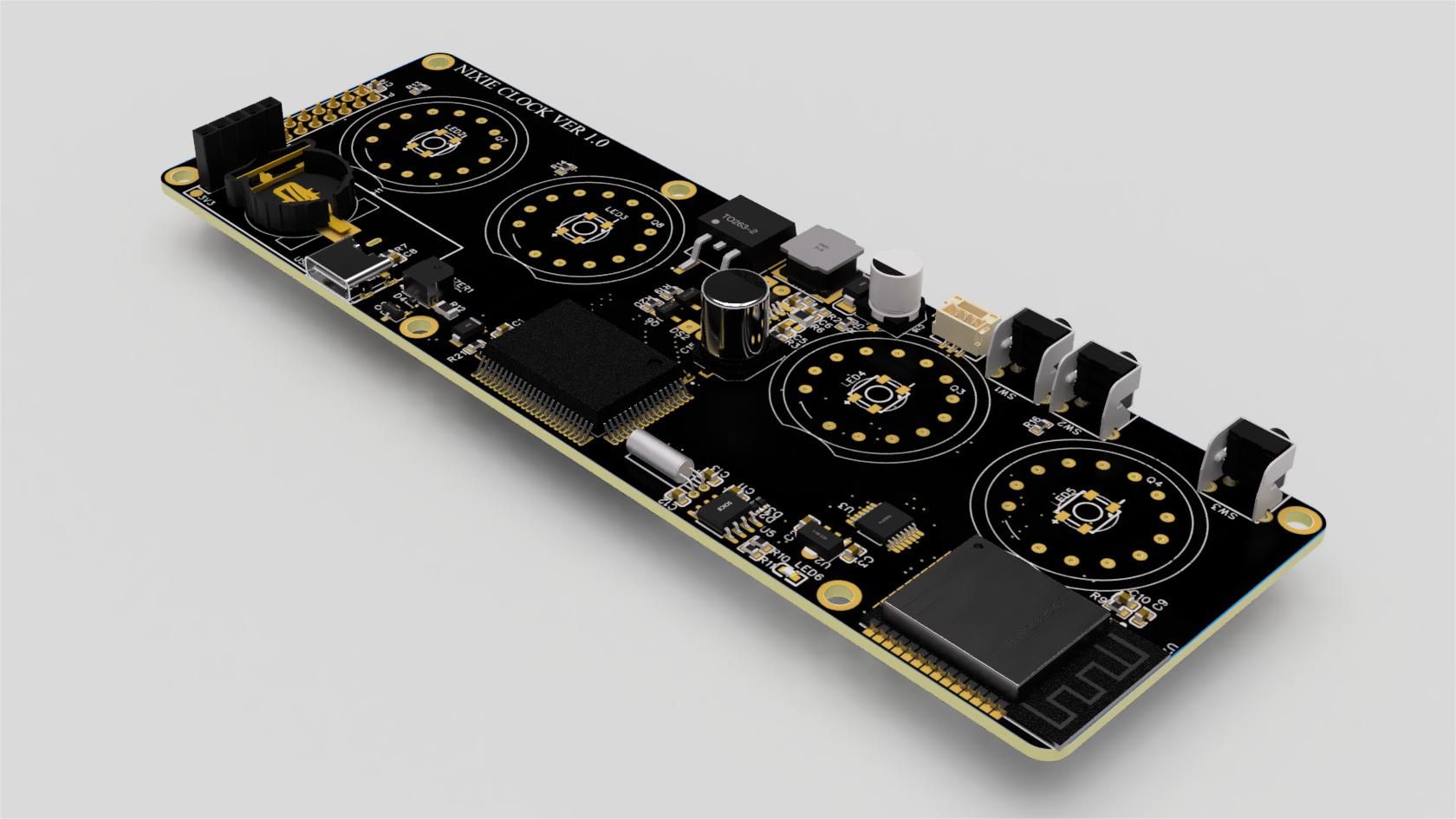
I've hidden a few little surprises; the back is practically bare, so I felt compelled to draw something.
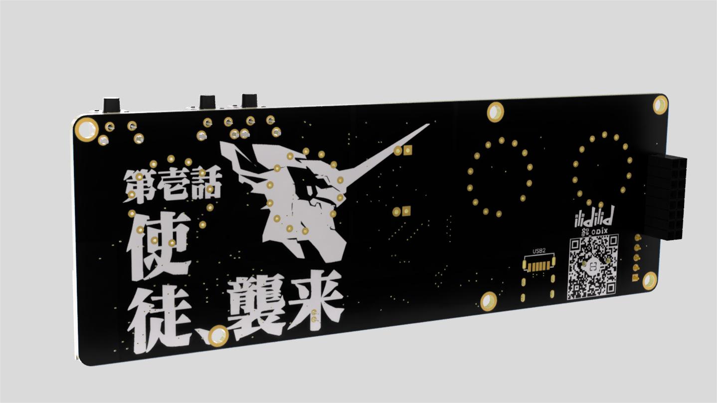
The board includes an RTC clock, intended for calibrating the time each time the computer is powered on, and not connecting to the internet at other times.
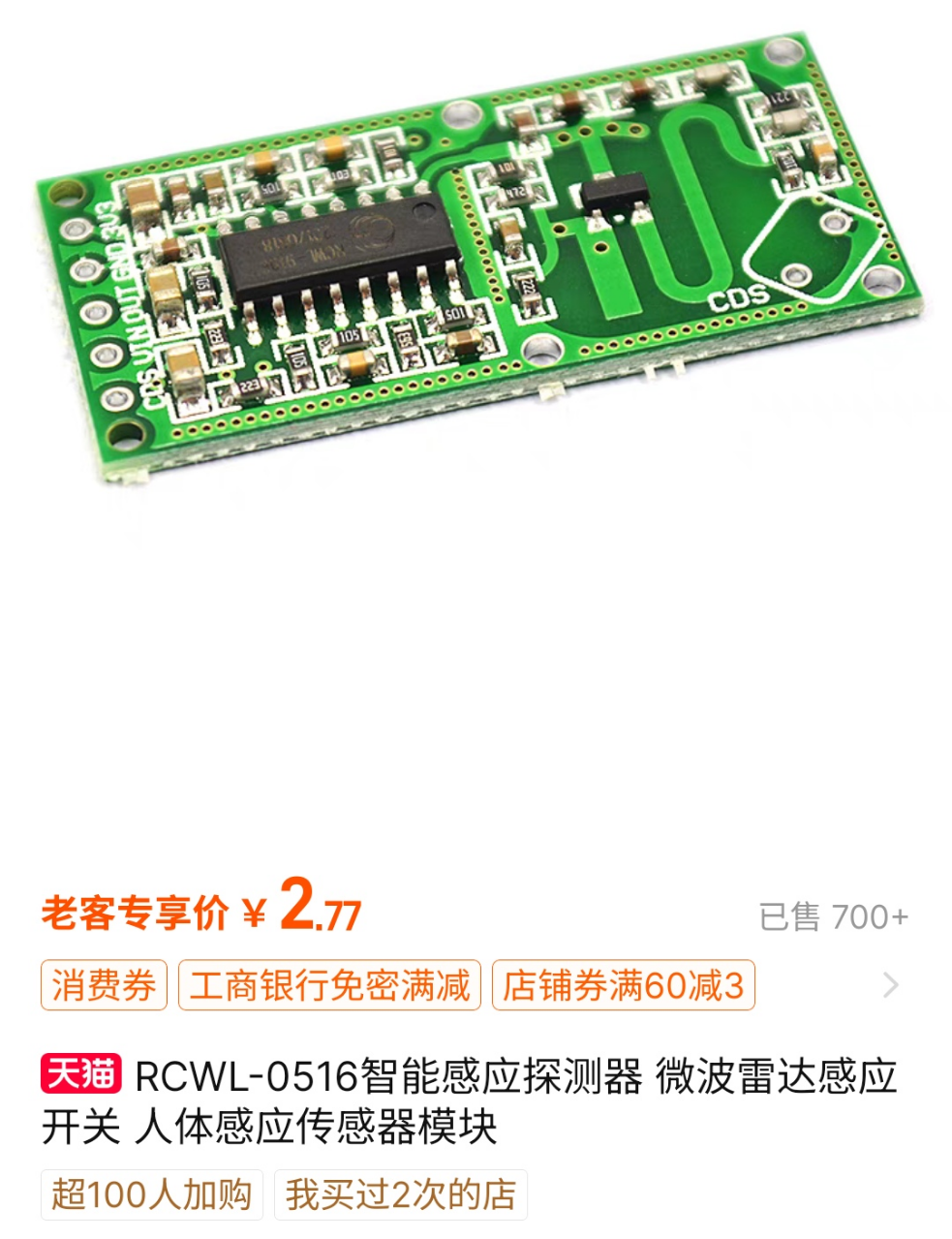
It also thoughtfully includes a radar sensor switch interface for detecting the presence of someone. This way, the glow tubes only light up when someone is near or constantly nearby, saving power and, more importantly, significantly reducing the glow tubes' operating time and lowering the probability of glow tube poisoning, extending their lifespan by several years.
Of course, I mainly like seeing the clock and the instantaneous 0-9 refresh of the tubes – that's a bit too electronic, so I need to look at it more often.
The board also features four RGB LEDs, placed under the bulb base for more color. However, I personally don't like RGB clutter, so whether to add them is entirely up to personal preference. There's also a small buzzer on the board for hourly reminders, and it can also be set as an alarm.
It's important to note that the glow tube should not be directly soldered onto the PCB. You need to purchase a pin header or an integrated lamp holder for soldering. My design uses a base like the one shown below, which is readily available and inexpensive on Taobao. Then, insert the glow tube into the base for easy replacement if it breaks. After

all this hardware talk, guess what? I haven't written any software at all! (hands on hips). It's not intentional; I changed jobs after designing it and was too busy, so I'm leaving it for now and will work on it later when I have time. Those who can't wait can search online for other open-source solutions. There are quite a few that use ESP32 for glow tubes; you can modify them to use them.
I've also attached my own wooden casing design; you can easily find a machining shop on Taobao to make it—it's not complicated. I have two designs, both attached. One is designed using Fusion360; you can check the online preview before deciding whether to use it.
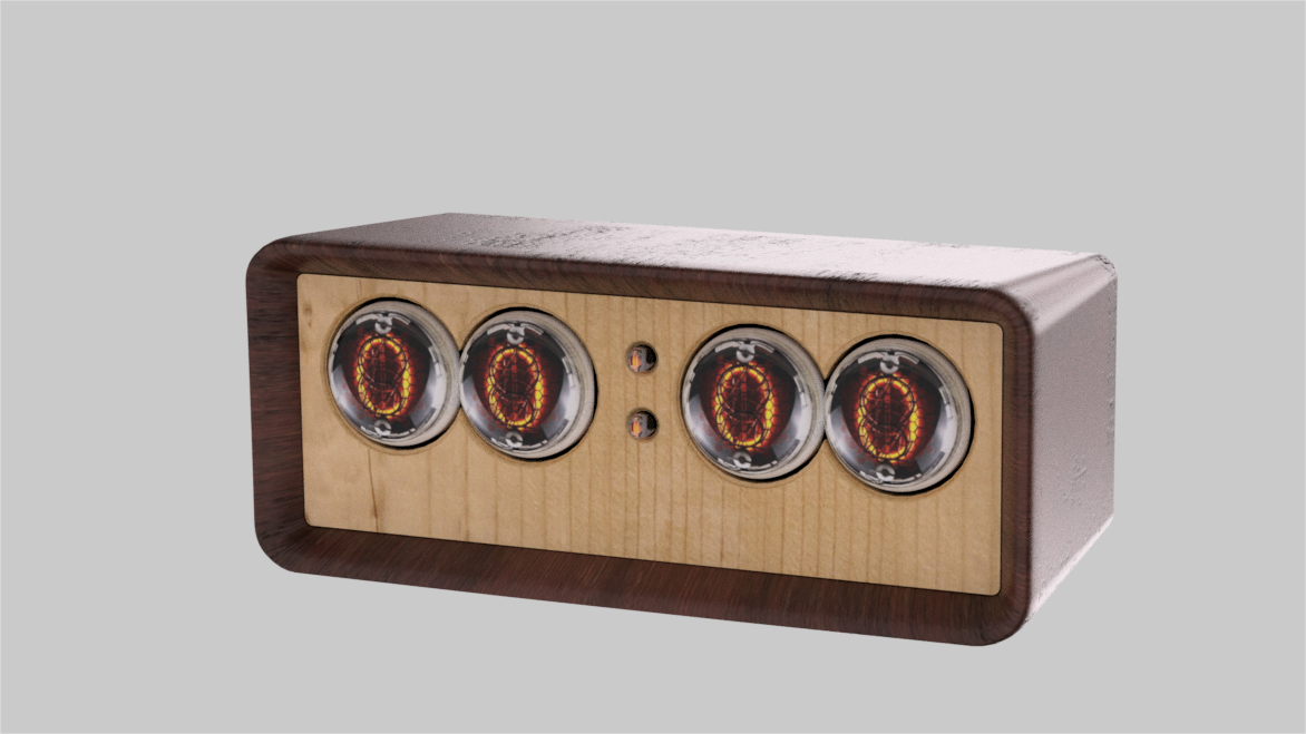
Casing online preview: Glow tube clock overall design preview.
Another square box: Another casing design for the glow tube clock.
Glow tube clock design solution v1.zip
Glow tube clock design scheme V2 .zip
PDF_Glow Tube Retro Industrial Style Clock—Based on ESP32.zip
Altium_Glow Tube Retro Industrial Style Clock—Based on ESP32.zip
PADS_Glow Tube Retro Industrial Style Clock—Based on ESP32.zip
BOM_Glow Tube Retro Industrial Style Clock—Based on ESP32.xlsx
94565
SA568AD-PLL-demod
SA568 150MHz FM/FSK Demodulation Phase-Locked Loop Module
The NE568/SA568AD is a high-frequency, high-bandwidth phase-locked loop (PLL) FM/FSK RF signal demodulation module
with a maximum operating frequency of 150MHz. A maximum demodulation bandwidth of 10MHz is recommended at an intermediate frequency (IF) of
70MHz. It can be used in conjunction with a 70MHz IF crystal filter, offering significantly better performance than typical hand-made LC bandpass filters.
It can be used for various RF problems in electronic design competitions, wireless audio/video demodulation and reception, satellite communication, etc.
The center frequency and demodulation bandwidth can be adjusted via potentiometers and changes to peripheral loop filters.
The high-bandwidth mode is suitable for demodulating video signals. When demodulating narrowband signals (such as FM broadcasts) with a 10MHz bandwidth, the signal level may be too low. For
demodulating narrowband signals, it is recommended to modify the circuit to use a lower total bandwidth.
For specific calculation formulas and applications, please refer to the chip datasheet.
PDF_SA568AD-PLL-demod.zip
Altium_SA568AD-PLL-demod.zip
PADS_SA568AD-PLL-demod.zip
BOM_SA568AD-PLL-demod.xlsx
94566
Design of a high-precision phase difference measurement circuit based on FFT and STM32
Frequency and phase difference measurement development board
Two signals are acquired at regular intervals by pa5 and pa6. Once the threshold is triggered, the data is immediately moved to a memory array. The discrete-time signal FFT is implemented by DSP library functions, and logic functions are written to extract the spectrum information.
PDF_High-precision phase difference measurement circuit design based on FFT and STM32.zip
Altium: High-Precision Phase Difference Measurement Circuit Design Based on FFT and STM32.zip
PADS: High-Precision Phase Difference Measurement Circuit Design Based on FFT and STM32.zip
BOM_Design of a High-Precision Phase Difference Measurement Circuit Based on FFT and STM32.xlsx
94567
ESP32-PICO-V3 Bluetooth Mouse
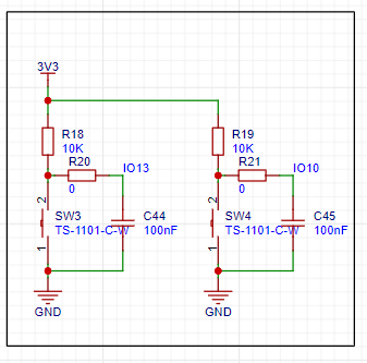
This project uses the ESP32 V3 control chip and the MPU6500 as a gyroscope. The buttons are used as the left and right mouse buttons, and the Bluetooth connection is handled by the main control chip.
This project utilizes the ESP32 V3 control chip and the MPU6500 as a gyroscope. Buttons are used to act as the left and right mouse buttons, with Bluetooth connectivity handled by the main control chip.
Signals are received via a ceramic antenna, filtered by a π-type filter, and then sent to the ESP32 for data processing.
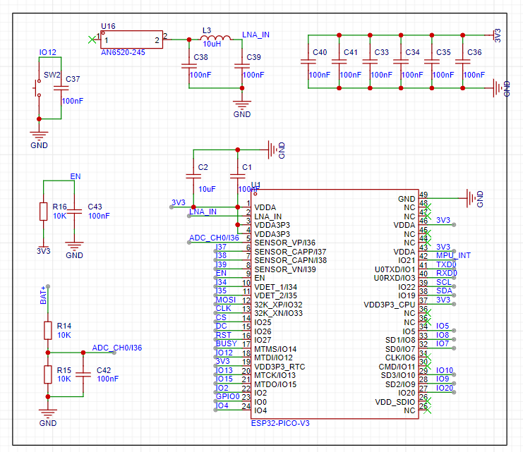
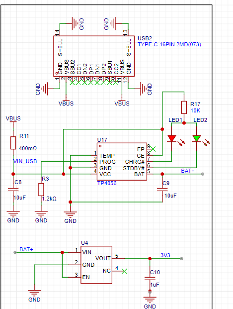
A TP4056 charging management chip charges the lithium battery and stabilizes it at 3.3V to power the circuit.
The MPU6500 provides 3-bit attitude sensing, which is then sent to the main control chip for processing. This simulates a mouse pad on a flat surface,
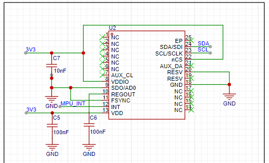
with two touch buttons acting as the left and right mouse buttons.
PDF_ESP32-PICO-V3 Bluetooth Mouse.zip
Altium_ESP32-PICO-V3 Bluetooth mouse.zip
PADS_ESP32-PICO-V3 Bluetooth Mouse.zip
BOM_ESP32-PICO-V3 Bluetooth Mouse.xlsx
94568
Desktop Embedded USB Expansion Dock/Cable Management Box
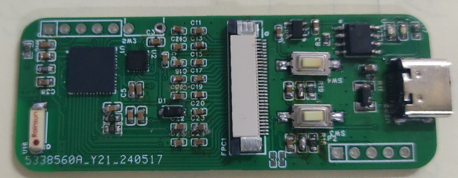
Designed for desktop USB expansion docks with 5cm+ round holes, based on the SL2.1s chip, it has high space utilization efficiency, dual A ports and dual C ports, and can even be used for cable routing, mimicking the smiley face cable management box that is already in mass production but cannot transmit data.
This desktop USB docking station design, based on the SL2.1s chip, is designed for desktops with a 5cm+ round hole. It boasts high space utilization efficiency, featuring dual USB-A and dual USB-C ports, and even allows for cable routing, mimicking the mass-produced "smiley face" cable management box that cannot transmit data.
The project includes two versions: one with only two USB-A ports, which can be directly integrated into commercially available "smiley face" cable management boxes and is relatively easy to solder;
the other, the Pro version, adds two more USB-C ports and includes a specially designed 3D shell (exported using FreeCAD; I'm a 3D novice, please excuse the design). The shell is too thin and may crack during printing; modifications are recommended.
Testing showed that both versions, regardless of whether they have USB-A or USB-C ports, can achieve near-full USB 2.0 performance.
M1.2*10 screws are used.
A USB wireless mouse and keyboard terminal storage box is included in the file; this is a personal design and can be used as needed.
Soldering Precautions:
1. The external capacitor for the crystal oscillator has a small package, making soldering difficult. It can be omitted (and still work);
2. The pin spacing of the Type-C female connector is relatively small, so be careful not to cause solder bridging;
3. Solder bridging may occur on the chip, so it is not recommended to use a soldering iron;
4. Given the small size of the components, please check for short circuits between the four connection points before powering on (I personally had a charger blown and a circuit breaker tripped due to a capacitor short circuit).
USB-Desktop-HUB.FCStd
USBCollector.FCStd
PDF_Desktop Embedded USB Expansion Dock - Cable Management Box.zip
Altium Desktop Embedded USB Expansion Dock Cable Management Box.zip
PADS_Desktop Embedded USB Expansion Dock_Cable Management Box.zip
94569
electronic


 京公网安备 11010802033920号

 2200RAG20IPF3KA


