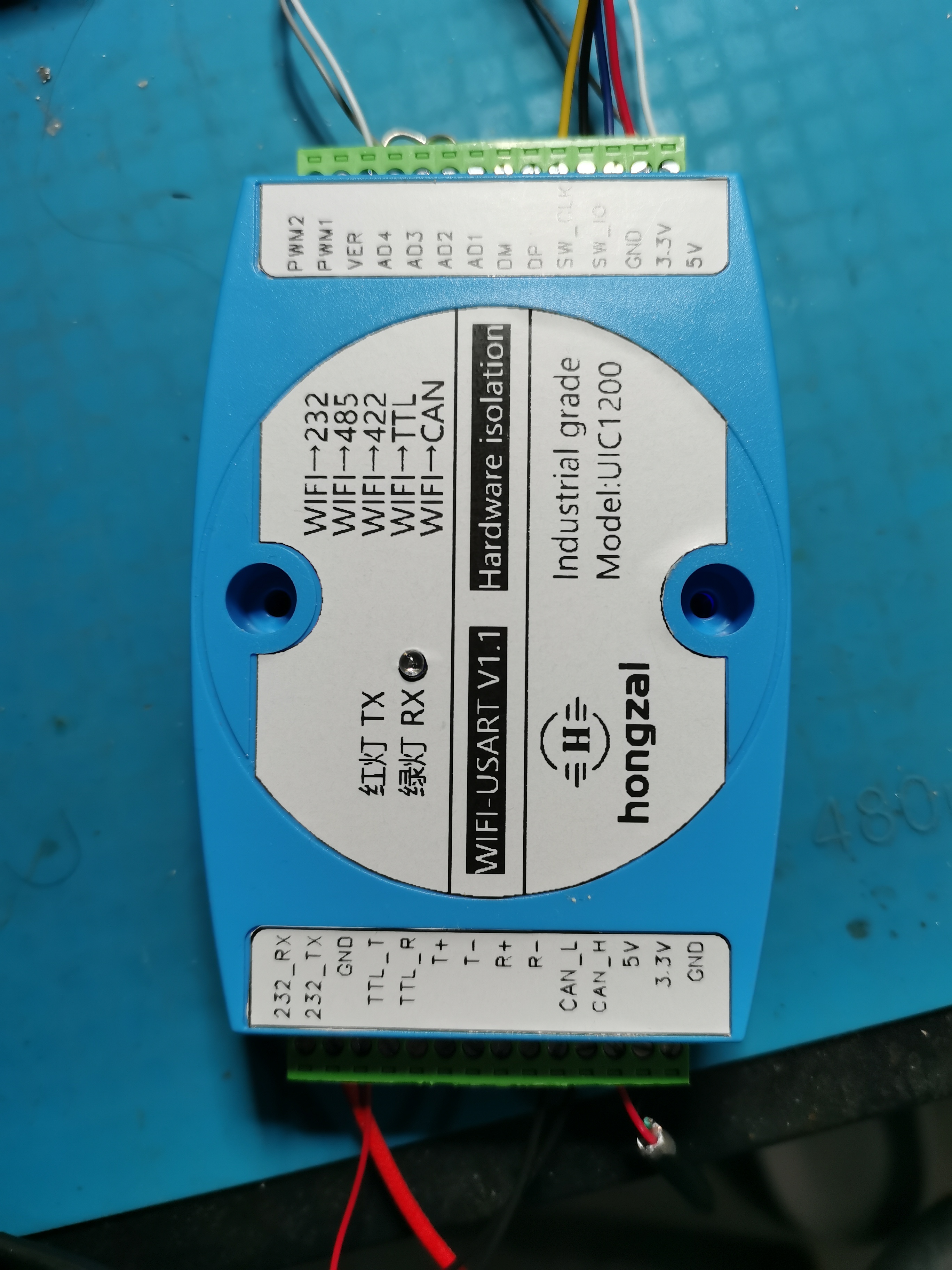
This wireless serial port, based on the ESP8266, enables remote serial communication.
No additional equipment is needed on the computer; simply installing virtual serial port software is sufficient. It features wireless serial-to-RS (RS-485, RS-422, RS-232, TTL, CAN) conversion, along with 4-channel AD voltage reading and 2-channel PWM output, meeting the daily debugging needs of engineers. It has undergone over a month of aging testing, with virtually no frame drops in the serial port. Occasional frame drops occur with faster CAN speeds, but not with slower speeds; this aspect requires optimization. Comments are welcome. The casing can be found on Taobao by searching "Industrial Control 4.0". This is a limited version; for the full version, please contact hzsxsg via WeChat.
CAN demo.mp4
PC software.zip
Program burning instructions.zip
Computer connection instructions.zip
Installation of burning software.mp4
Serial Port Function Table.xlsx
ESP8266 parts.zip
STM32 parts.zip
PDF_Wireless Serial Port to 485, 422, 232, TTL, CAN (LAN Version).zip
Altium_Wireless Serial Port to 485, 422, 232, TTL, CAN (LAN Version).zip
PADS_Wireless Serial Port to 485, 422, 232, TTL, CAN (LAN Version).zip
BOM_Wireless Serial Port to 485, 422, 232, TTL, CAN (LAN Version).xlsx
94898
ZYNQ7z020_baseboard
ZYNQ7020 base plate
This project is a baseboard designed for the 7020 core board of the open-source platform "Power On and Smoke". The core board link is: https://oshwhub.com/z_star/zynq7020-core-board-and-various-rf-modules
PDF_ZYNQ7z020_baseboard.zip
Altium_ZYNQ7z020_baseboard.zip
PADS_ZYNQ7z020_baseboard.zip
BOM_ZYNQ7z020_baseboard.xlsx
94899
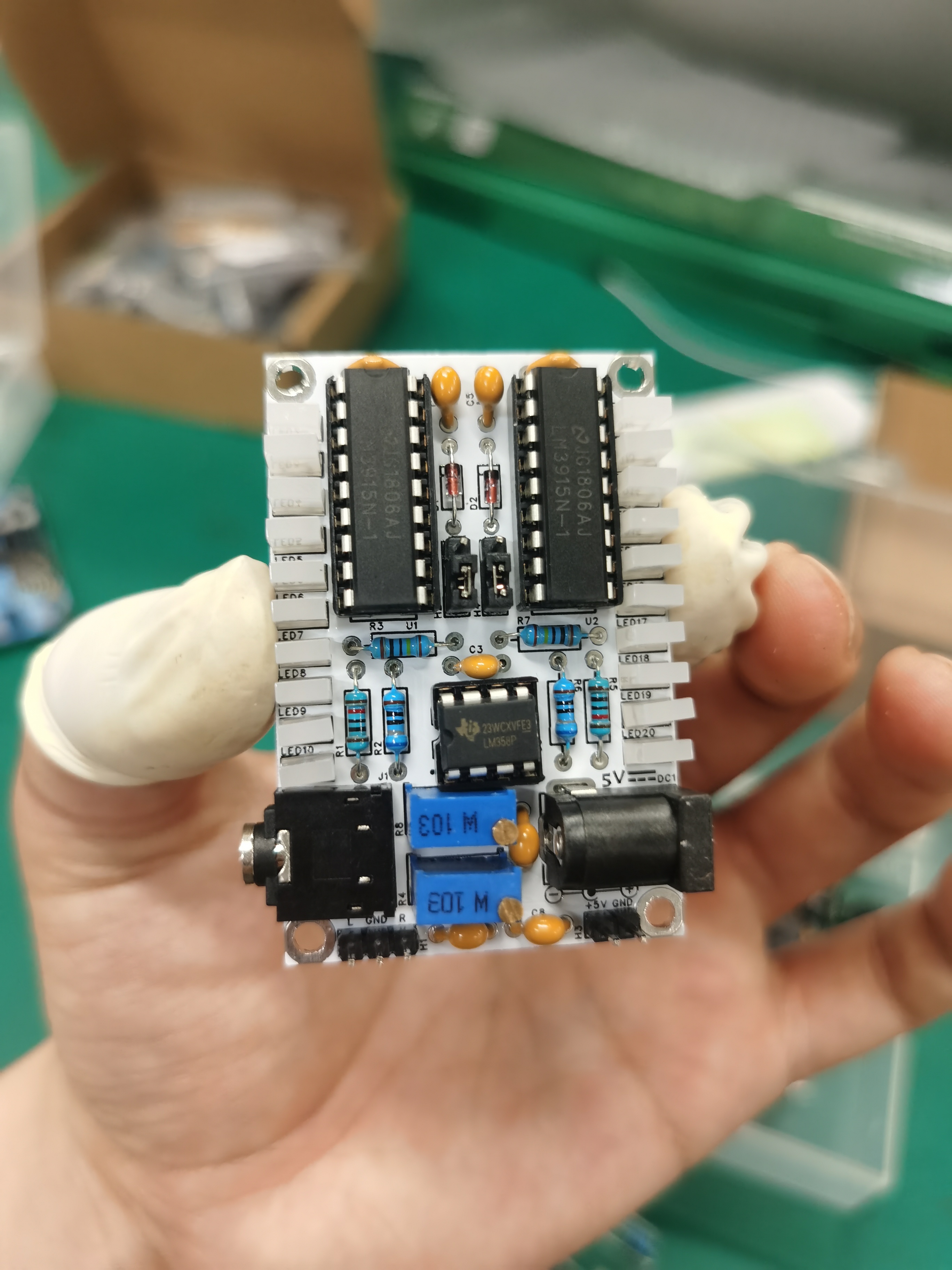
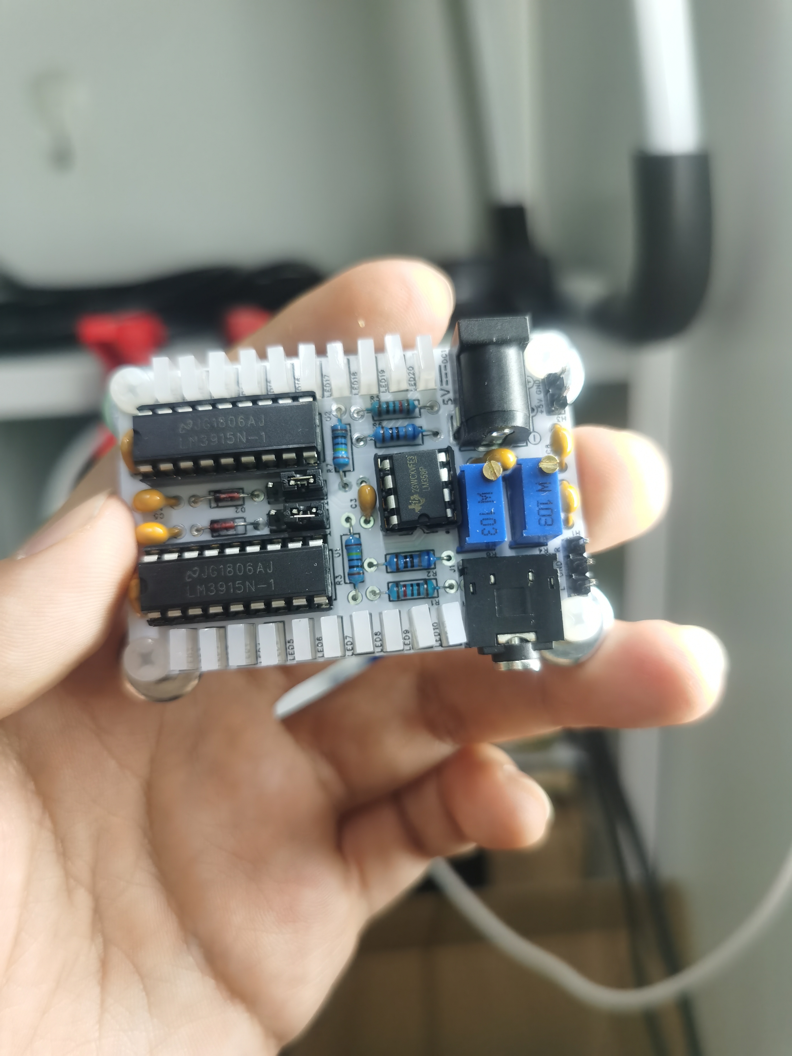
LM3915 Audio Level Indicator
A device that lights up LEDs one by one according to the magnitude of the input audio signal.
Engineering Principle: The LM3915 is a 10-LED strip driver chip, similar in function to the LM3914. The LM3915 lights up the LEDs one by one according to the input voltage. In this circuit, the LM358 amplifies the audio signal, and the LM3915 provides a direct display of the audio signal, allowing users to intuitively experience the impact of the audio. Function: Used to enhance multimedia equipment such as audio systems (audio companions). It can also be used to measure the amplitude of analog signals. The LM3915 (logarithmic indicator) can be replaced with an LM3914 (linear indicator) to create a voltmeter. Operating Conditions: The audio input needs to be connected to a preamplifier (or a signal can be provided via a header pin; before the power amplifier, it can be directly output from the computer/mobile phone audio port; if too many LEDs need to be lit, the potentiometer can be adjusted). The power supply is 5V DC, positive inside and negative outside (or powered via a header pin). A 1-to-2 audio splitter and a USB to DC005 converter can be used to directly power and provide signals to the circuit via a computer. Test parameters: Testing showed that the current draw was only 40mA when all LEDs were lit and only 2mA when all LEDs were off, demonstrating extremely low power consumption. It also did not interfere with the original circuitry and could be modified for use on any multimedia device with a 3.5mm plug. The circuit includes four screw holes and pin headers for easy mounting (screws or magnets can be used to attach it to other devices). It is also easy to embed into other DIY projects (such as speakers). The LEDs are 2*5*7 square, and the LED colors can be selected as needed. The lighting sequence is LED1 to LED10, and LED11 to LED20.
Demo video address: [link to demo video]

PDF_LM3915 Audio Level Indicator.zip
Altium_LM3915 Audio Level Indicator.zip
PADS_LM3915 Audio Level Indicator.zip
BOM_LM3915 Audio Level Indicator.xlsx
94900
Tiny1-B_CT256 module power supply
The CT256 module is the power supply module for the Tiny1-B module. It can be directly connected to a mobile phone via CTC and has been successfully verified. Note that the board is a 2-layer, 1mm thick board!
The original power supply module wasn't powerful enough, causing the shutter to fail and resulting in image ghosting. Replacing it with the RY1303 power supply module stabilized the current significantly, solving a major problem.
Note that the board is a 2-layer, 1mm thick board!
2.mp4
1.mp4
PDF_Tiny1-B_CT256 Module Power Supply.zip
Altium_Tiny1-B_CT256 module power supply.zip
PADS_Tiny1-B_CT256 module power supply.zip
BOM_Tiny1-B_CT256 Module Power Supply.xlsx
94902
DC-DC converter based on XL4015E1 chip 12V-5V step-down circuit
Based on the XL4015E1 chip,
this step-down circuit design can theoretically achieve: VIN=8V~36V, VOUT=5V/5A.
A step-down circuit based on the XL4015E1 chip: 1. Component parameters are referenced from the official XL4015 DEMO board manual: https://www.xlsemi.com/products_DC_DC_buck_mv.html 2. Circuit schematic design is referenced from the official XL4015 DEMO board manual and Teacher Tang's lectures on the electronics competition on Bilibili. 3. Layout and routing design are referenced from Teacher Tang's lectures on the electronics competition on Bilibili:
【Open Source XL4015 Schematic and PCB, Step-by-Step Guide to Drawing XL4015 Schematic and PCB, Essential for Electronics Competitions... Yangtze University】 https://www.bilibili.com/video/BV1Bm4y157a7/?share_source=copy_web&vd_source=8812782178457230c0ef3ee575e5a0e4
After testing, it can stably output 4-5V. Under no load conditions, after reaching 5V, it gradually decreases by 0.01V.
The original intention of this project was to record my learning process. I also hope that experts can offer suggestions or opinions, and I will learn from everyone and continue to learn.
April 28 (1).mp4
PDF_DC-DC 12V-5V Step-Down Circuit Based on XL4015E1 Chip.zip
Altium_DC-DC 12V-5V step-down circuit based on XL4015E1 chip.
PADS_DC-DC 12V-5V step-down circuit based on XL4015E1 chip. zip
BOM_DC-DC 12V-5V step-down circuit based on XL4015E1 chip.xlsx
94903
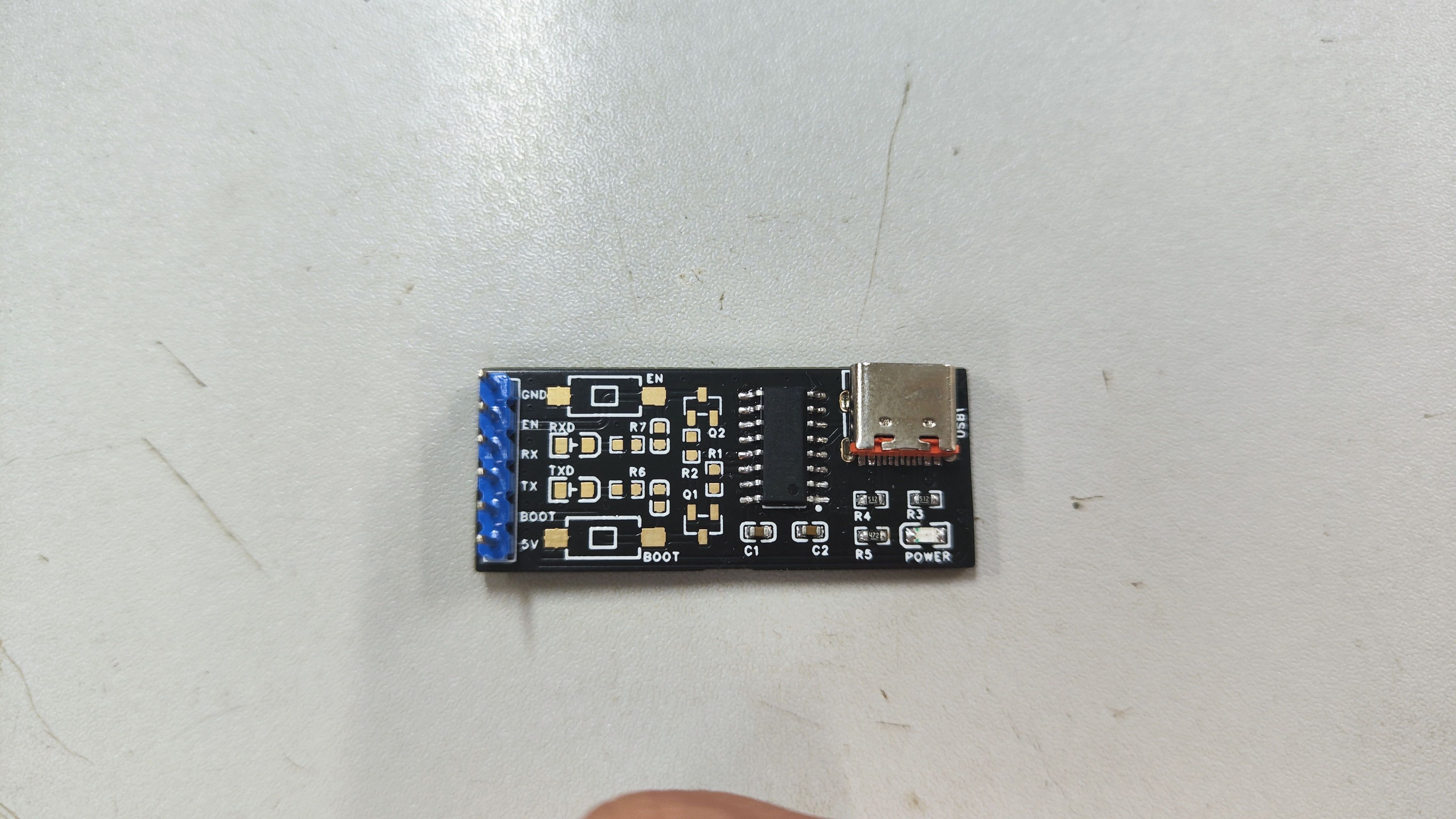
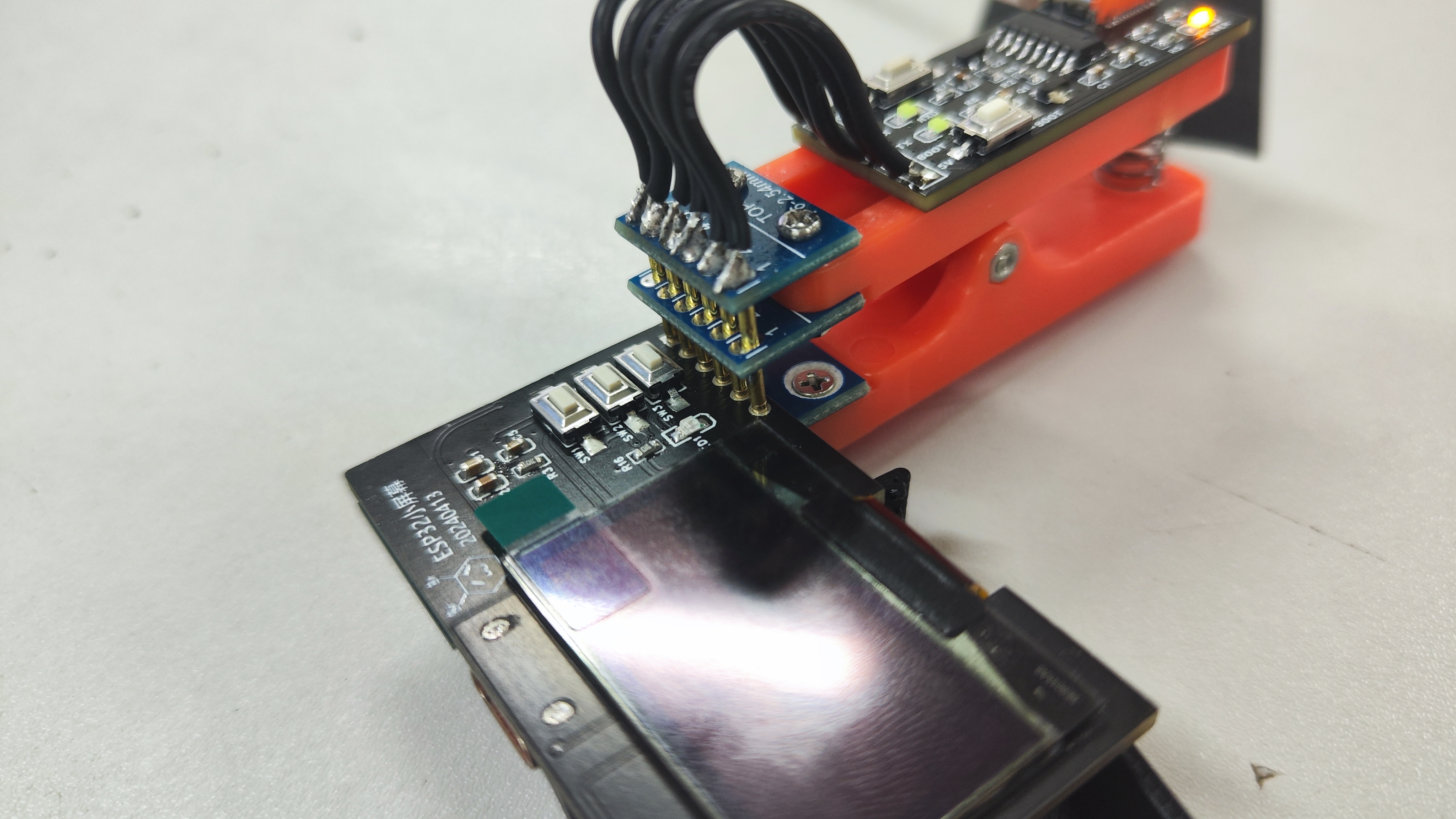
ESP Auto Burner
This project is a simple ESP32 auto programmer based on CH340C. It can be used as a standalone serial port module or with a programming clip to enable chip downloading.
This project is a simple ESP32 auto programmer based on the CH340C chip. It can be used independently as a serial port module (in this case, the buttons, matching capacitors, transistors, and two 10kΩ resistors do not need to be soldered, as shown in the image below).
(This image is from the first-generation board; the LED direction is reversed. The open-source board can be directly soldered on this board.) It
can also be used with a programming clip (as shown in the image below). The design aims to eliminate the need for a download circuit during product design, reducing the probability of soldering errors, minimizing component count, and saving costs.
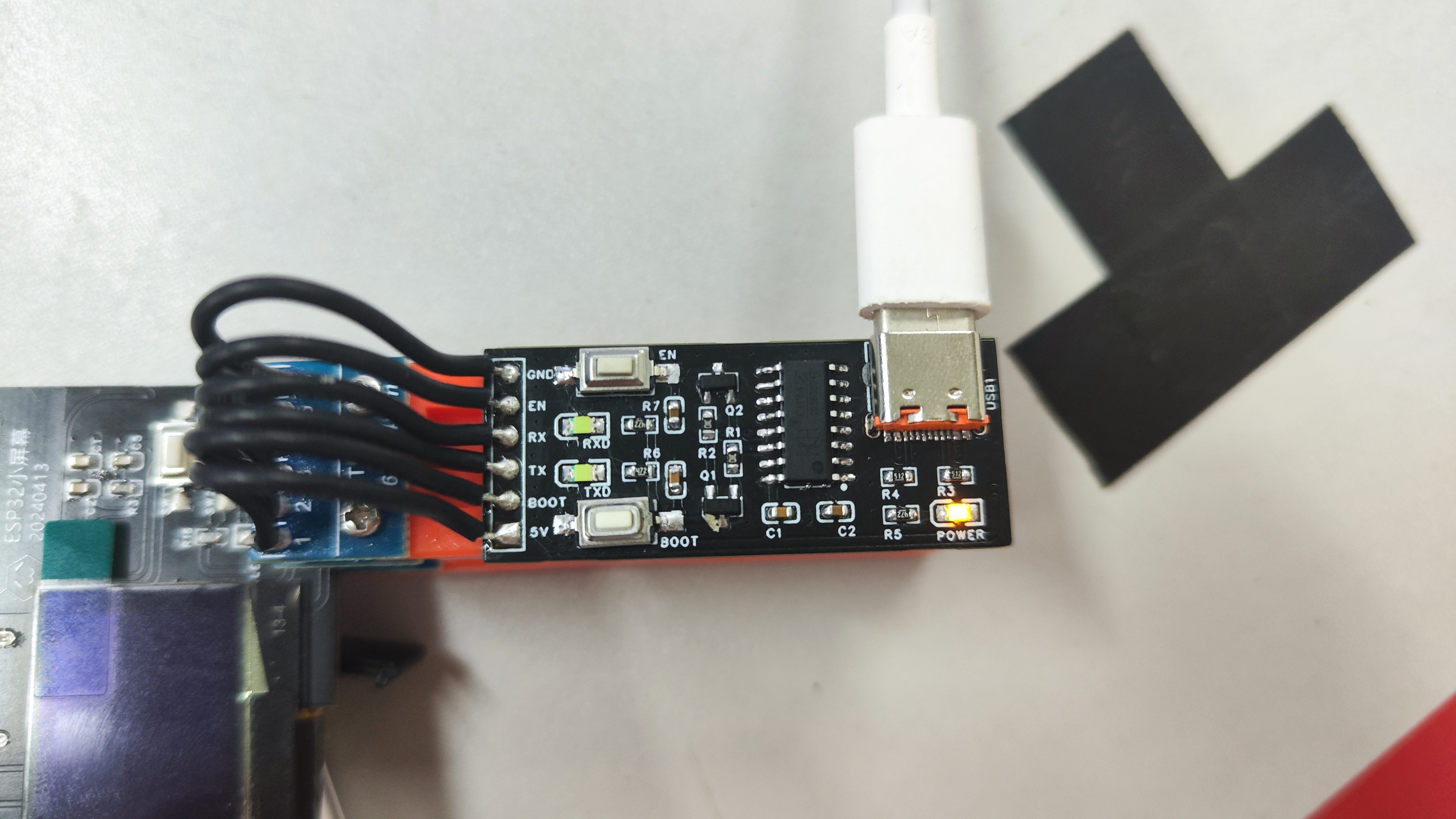
Although it's called an ESP32 auto programmer, the BOOT and EN pins are not fixed. Theoretically, it's applicable to serial port downloading of all chips with the same principle as the ESP32 (Note: the RX and TX order remains unchanged; the object being programmed still needs to be designed according to RX->TX, TX->RX).
Finally, do not order through the BOM (because capacitors, resistors, etc., are not bound to specific models); simply buy them online according to their model numbers.
PDF_ESP Auto Burning Folder.zip
Altium_ESP Auto Burning Folder.zip
PADS_ESP Auto Burning Folder.zip
BOM_ESP Auto Burning Folder.xlsx
94904
electronic
 Schematic diagram:
 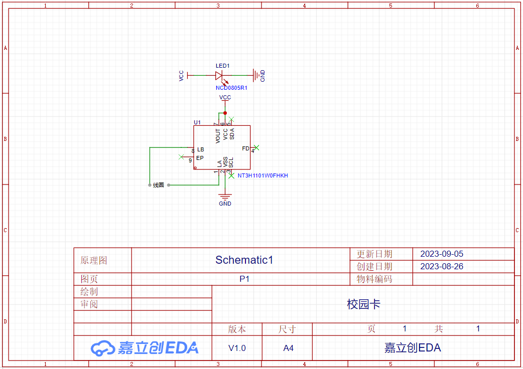 PCB:
PCB:


 京公网安备 11010802033920号

 2200SGH1001F3LA


