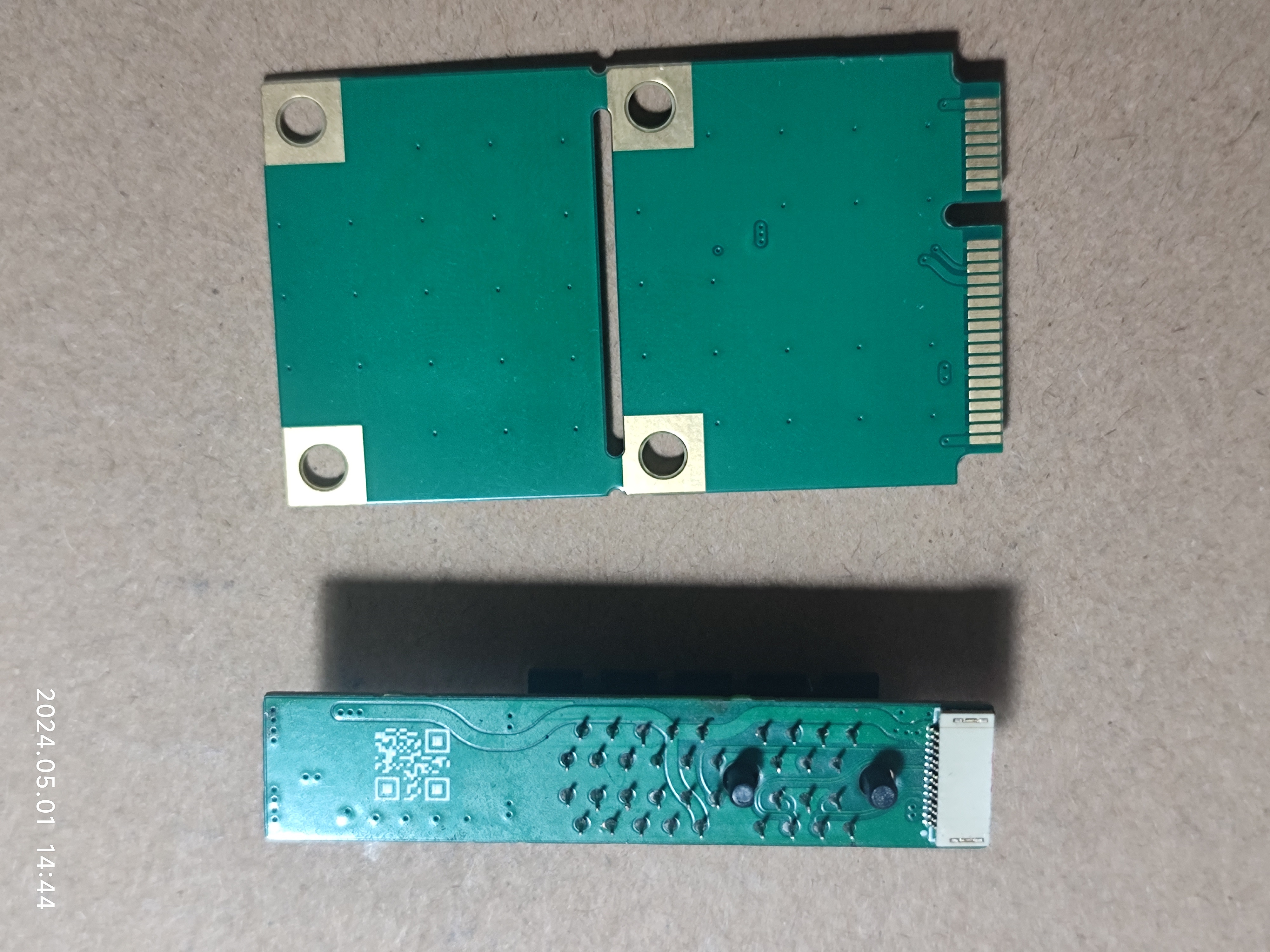
The MiniPCIe section later added two-way socket soldering positions, allowing for free choice of wire direction.
This has been verified.
Analog Electronics Course Project—Waveform Superposition + Butterworth Low-Pass Filter
This project mainly describes the simple practical application of the Butterworth low-pass circuit. It includes how to build the circuit for simulation, calculate relevant parameters, and select components. It then proceeds to the actual circuit debugging and the achieved filtering effect.
一、设计要求
(1)信号发生器提供两路信号,A路:幅值2V,频率150Hz的正弦波,B路:幅值1V,频率5KHz的正弦波,利用运放搭建加法电路,实现两路信号的叠加。设立测试点,测量信号求和后的波形。
(2)搭建有源低通滤波电路,对之前的求和电路进行滤波,滤除高频成分,设立测试点。
二、方案选择与论证
第一部分:利用运放搭建求和电路
在选择同相加法和反相加法时,需要考虑它们的特性和应用情况。同相加法器的输入阻抗大,输出阻抗小,这意味着一部分输入信号会被消耗在输入端,但是输出信号的稳定性较高;反相加法器的输入阻抗小,输出阻抗大,意味着较少的输入信号会被消耗在输入端,但是输出信号的稳定性较低。反相加法器的另一个缺点是其输出电压反相,这意味着在某些情况下可能需要额外的处理才能满足需求。因此,这里的两路输入信号,A路:幅值2V,频率150Hz的正弦波,B路:幅值1V,频率5KHz的正弦波,略有消耗对后级电路影响可以忽略,且可以得到稳定性较高的同相输出信号,所以在此选择同相加法电路。但是同相加法电路可能会引入一些噪声和失真,这会降低电信号的质量,降低信噪比,但这可以在后级滤波电路时解决。
第二部分:搭建有源低通滤波电路
有源低通滤波电路是一种滤波器,它不仅仅包含无源组件(如电阻、电容、电感),还包含了有源组件,例如晶体管或者运算放大器等。它的主要形式是有源RC滤波,也被称作电子滤波器。与无源滤波器相比,有源低通滤波电路的优点在于它可以提供更好的滤波效果,并且可以通过调整有源元件的参数来改变滤波特性。一阶有源低通滤波电路是构建更高级别的二阶、高阶有源低通滤波电路的基础单元。具体来说,这种电路的工作原理是利用有源元件对输入信号进行放大,然后通过低通滤波器滤除高频噪声。由于使用了有源元件,有源低通滤波电路具有较高的增益和较低的输入阻抗,可以提供更好的滤波效果。增加滤波器的阶数可以提高其选择性(即更陡峭的频率响应),但是同时也会增加滤波器的复杂度和成本。过高的阶数可能会导致滤波器不稳定。因此,选择适当的阶数需要根据具体的应用需求进行权衡。在此选择二阶有源滤波电路。(使用一阶有源滤波器进行仿真时,波形已经有明显的失真,达不到良好的滤波效果,制作成实物的效果几乎可以肯定会很差,因此需要采用更高阶的滤波网络)。
二阶有源滤波电路主要有两种结构,分别是Sallen-key和多路反馈(KFB)。这些滤波电路使用了运算放大器作为无限增益器件,形成了无限增益多端反馈电路。二阶有源滤波电路还包括四种类型的有源滤波器,分别是巴特沃斯、贝塞尔、切比雪夫和椭圆滤波器。
一、巴特沃斯滤波器(Butterworth filter):
优点:
1、通带内的频率响应曲线最大限度平坦,没有起伏。在通带内,信号的波形能够尽可能地保持原始状态,不会产生失真。
2、阻带内逐渐下降为零。这意味着在阻带内,信号会被完全屏蔽,不会对通带内的信号产生影响。
缺点:
1、设计时需要确定通带截止频率、阻带频率等参数。
2、巴特沃斯滤波器的阶数越高,通带内的频率响应曲线越平坦,但阻带内的衰减也会越慢,导致滤波器的性能越复杂。
二、贝塞尔滤波器(Bessel filter):
优点:
1、在所有滤波器中线性相位特性最佳的。意味着,在通带的频率范围内,信号的相位恒定,这对于许多应用来说是非常重要的。
缺点:
1、幅频特性的选频特性较差。这意味着在通带和阻带之间的过渡区域,贝塞尔滤波器的性能可能不如其他类型的滤波器。
2、贝塞尔滤波器[5]的阻带下降较慢,可能会导致一些不必要的干扰。
三、切比雪夫滤波器(Chebyshev filter):
优点:
1、在频域内能够更加灵活地控制通带波纹和阻带衰减,能够在保证通带内波纹最小的同时,实现在频域上的等波纹设计。
2、在需要高通或低通滤波时,具有更好的性能。它可以在频域内更精细地控制滤波效果,从而达到更精确的滤波目标。
缺点:
1、阻带衰减较差,在滤除高频或低频信号时,切比雪夫滤波器可能无法彻底阻止这些信号的渗透,从而影响滤波效果。
四、椭圆滤波器(Cauer filter):
优点:
1、等波纹特性:椭圆滤波器的通带和阻带都具有等波纹特性,在这两个区域内,滤波器的性能良好,并且能够提供稳定的滤波效果。
2、较低的阶数:对于同样的性能要求,椭圆滤波器所需的阶数比其他类型的滤波器更低。能够在保证滤波效果的同时,减少资源消耗和计算量。
3、窄的过渡带:椭圆滤波器能获得较其他滤波器为窄的过渡带宽,在某些需要陡峭过渡带的应用中特别有优势。
4、逼近理想滤波器:椭圆滤波器的设计方法能更好地逼近理想的高通滤波器的特性,使得它能在某些需要高通滤波的应用中表现优异。
缺点:
1、 它的设计和实现比较复杂。
2、 在过渡带附近的性能较为敏感,因此在设计和调试时需要格外注意。
综上所述:在此次课程设计中选用巴特沃斯低通滤波器的方案。虽然在阻带的衰减速度相较于其它几种方案较慢,但相比与一阶的低通滤波器的频率响应陡峭程度已经有了很大的提升。(仿真中可看到明显效果)并且输入端的两路信号分别为150Hz和5KHz,相差巨大,可以通过设计好滤波网络的RC值让截止频率逼近150Hz,不会出现高频噪声影响的问题。并且通带内的频率响应曲线最大限度平坦,没有起伏。信号的波形能够尽可能地保持原始状态,不会产生失真。阻带内逐渐下降为零。这意味着5KHz的信号会被完全屏蔽,不会对通带内的信号产生影响。截止频率的计算也很简便,方便设计。
三、电路原理方框图
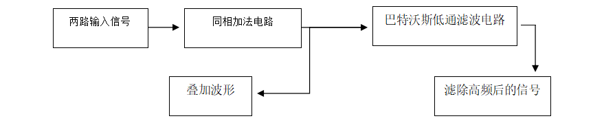
该电路包含两个组成部分,分别是运放搭建的加法电路和巴特沃斯低通电路。信号发生器提供两路信号,加法电路对两路信号求和A路:幅值2V,频率150Hz的正弦波,B路:幅值1V,频率5KHz的正弦波,实现两路信号的叠加。巴特沃斯低通滤波电路对前路的叠加信号进行滤波,滤除高频成分,得到A路的输入信号。
四、设计及仿真验证
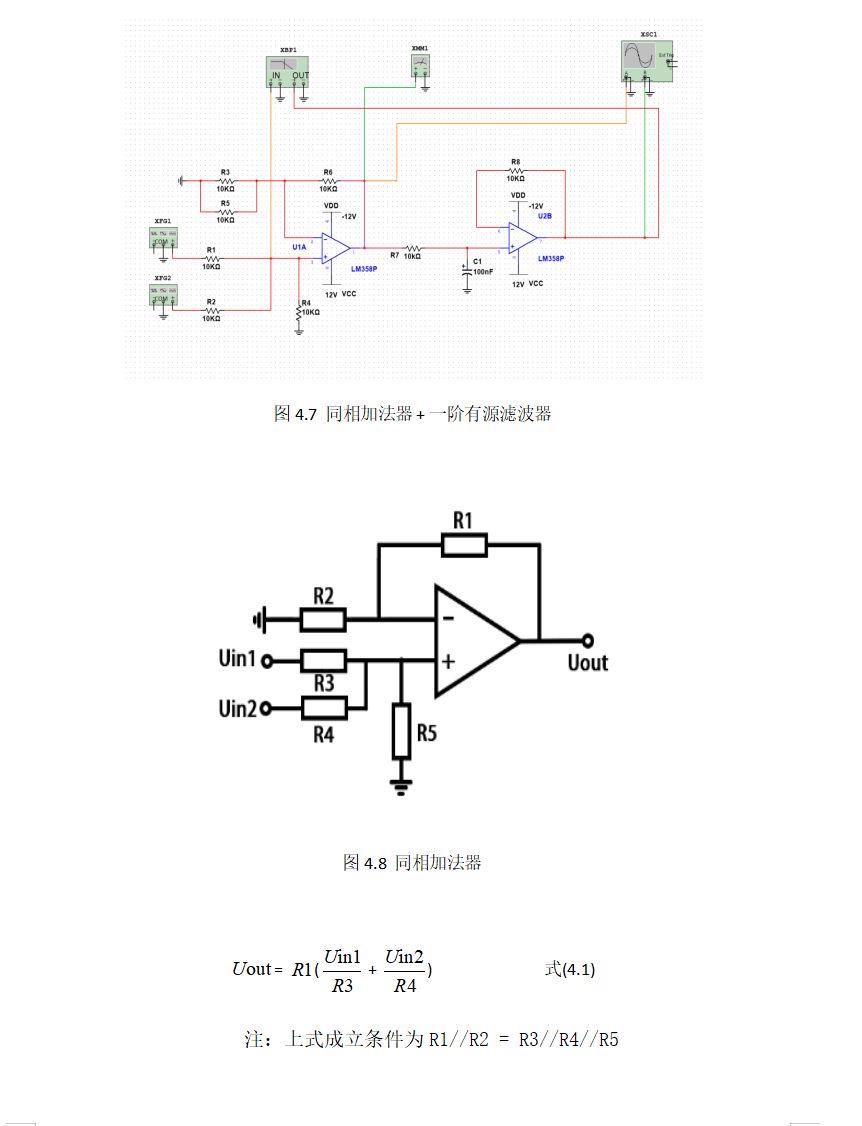
4.1单元电路及元器件选用
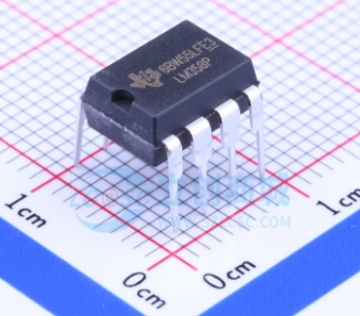
1. Operational Amplifier (op-amp): The general-purpose op-amp LM358P is selected. It has wide applications, numerous reference cases, complete TI official reference materials, and is inexpensive. However, it should be noted that it cannot be directly replaced with a voltage comparator (such as LM393) because it lacks comparator functionality. It also lacks internal phase compensation circuitry, which may lead to circuit instability. A phase compensation capacitor can be added during the design to prevent op-amp self-oscillation, but in actual testing, it did not oscillate without it, so it was omitted here to save materials. (See the attached chip manual for details)
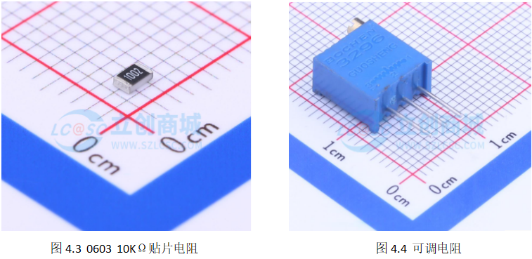
2. Resistors: Common 10KΩ 0603 package surface mount resistors are selected, which are small and inexpensive. (Here, I prioritize a compact and refined board design. Beginners may find soldering 0603 package surface mount resistors difficult; consider your soldering ability and choose 0805 package or through-hole resistors.)
3. Variable Resistor: A variable resistor is needed in the filter network to adjust the cutoff frequency. A common 10KΩ variable
resistor ; its resistance value can be adjusted by selecting the correct knob, making it convenient and easy to use. (All the above components can be purchased from LCSC Mall or Taobao)
4. Capacitors: To filter out the 5kHz high-frequency sine wave, theoretically the larger the capacitance, the better. However, considering factors such as actual size and price, we chose common 100nF 0603 package surface-mount capacitors, which are small and inexpensive.
5. Pin headers: Convenient for connecting to oscilloscopes and power
supplies. A BOM list is available.
4.2 Overall Circuit Design
Here, I used Multisim software for simulation, circuit construction, and effect testing. We can use this method in all project design processes to avoid unnecessary waste of manpower and resources.
4.3 Simulation and Result Analysis

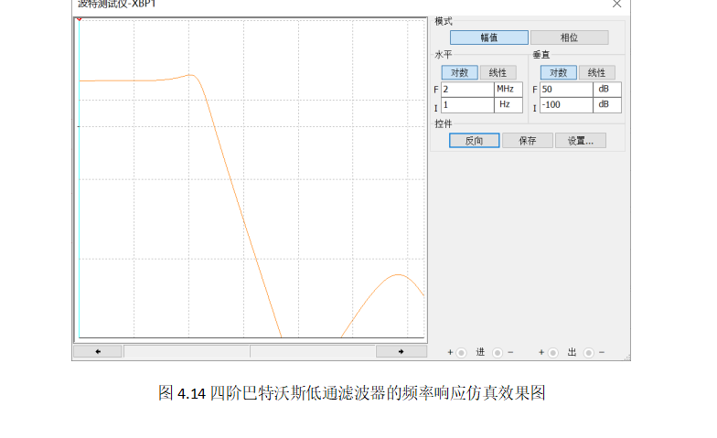
We can see that the effect achieved by the simple first-order low-pass filter circuit is significantly distorted. Therefore, we introduce a Butterworth low-pass filter circuit here. Under similar cutoff frequencies, it can be clearly observed that the transition region of the Butterworth low-pass filter is steeper than that of the first-order low-pass filter. While a fourth-order Butterworth low-pass filter offers a flatter passband in practical applications, its frequency drop-off rate slows down with increasing order. This not only increases design complexity but also makes it prone to a bulge in the passband due to the quality factor Q if the parameters are not properly tuned. Furthermore, since the LM358 only integrates two op-amps, using a fourth-order Butterworth filter increases material consumption and may be more cumbersome to tune, potentially resulting in performance inferior to a second-order Butterworth low-pass filter. Therefore, a second-order Butterworth filter was ultimately chosen for the prototype.
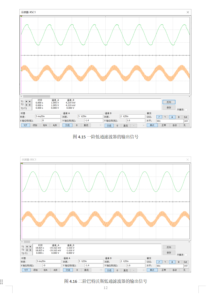


Under the same measurement dimensions, significant distortion was clearly observed in the output waveform of the first-order low-pass filter, even with the cutoff frequency set close to 150Hz. It's easy to predict that under real-world interference, the waveform distortion would be even greater, which is unacceptable. In contrast, the improved Butterworth low-pass filter solution produced a completely distortion-free output waveform, ensuring the filtering quality of the prototype. The fourth-order and second-order Butterworth low-pass filters produce almost identical signal outputs in simulations, making the second-order filter the optimal choice due to its ease of debugging and material savings.
V. Hardware Fabrication and Debugging
5.1 PCB Design and Fabrication
A TVS diode could be connected to each of the two power signal inputs to absorb surge voltages. However, the power signal input requirements are not stringent in this design, so it was omitted to save materials. A phase compensation capacitor with a typical value of 22pF could be connected in parallel with the negative feedback resistor to prevent self-oscillation, but after selecting suitable components, it was found that self-oscillation did not occur, so it can also be omitted. An adjustable resistor is used in the filter network to allow for adjustable cutoff frequency. Several extra resistors and capacitors can be placed in the input and output sections as spare positions; in actual fabrication, these are left unsoldered, making it easier to avoid flying wires if needed. Pin headers are used as test interfaces in the design, especially GND; several can be placed for easier wiring. In actual testing, it was found that having only two GND interfaces was not very convenient. The remaining parts are connected according to the internal structure of the operational amplifier shown in the diagram below, based on the simulation circuit.

During the layout process, copper plating was used for both 12V power supplies to provide sufficient current carrying capacity. The signal section and power section were laid out separately to avoid interference and were grounded. Because the circuit connection here is very simple, the global routing was kept as free of vias as possible to ensure smooth wiring and avoid right-angle traces that could cause signal reflection and interference. Finally, some restricted areas were placed during copper plating to remove sharp copper areas and dead copper (islands) to avoid antenna effects. (Actually, the circuit here is very simple. For convenience, breadboards or perforated boards can also be used to build the circuit. However, it may not be as stable. If a short circuit is encountered during the defense, it will burn out... Anyway, building a board is free [doge dog head for protection]).
5.2 Hardware debugging and test results
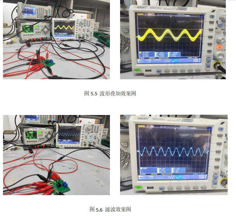
show that the measured results are very close to the simulation results. When the two variable resistors are adjusted to approximately 6.4KΩ, the cutoff frequency is the theoretical value of 175.84Hz, and the filtered measurement signal has almost no distortion.
Special note: Due to my limited ability, the Butterworth filter circuit used here is a combination of information I found from various sources and other people's experience. This is just the simplest application; I hope it will be helpful to beginners. Criticism and corrections from experienced users are also welcome. (Doge)
PDF_Analog Electronics Course Project—Waveform Superposition + Butterworth Low-Pass Filter.zip
Altium_Analog Electronics Course Project—Waveform Superposition + Butterworth Low-Pass Filter.zip
PADS_Analog Electronics Course Project—Waveform Overlay + Butterworth Low-Pass Filter.zip
BOM_Analog Electronics Course Project—Waveform Overlay + Butterworth Low-Pass Filter.xlsx
Used to drive brushless motors with drive, and can achieve stepless speed regulation.
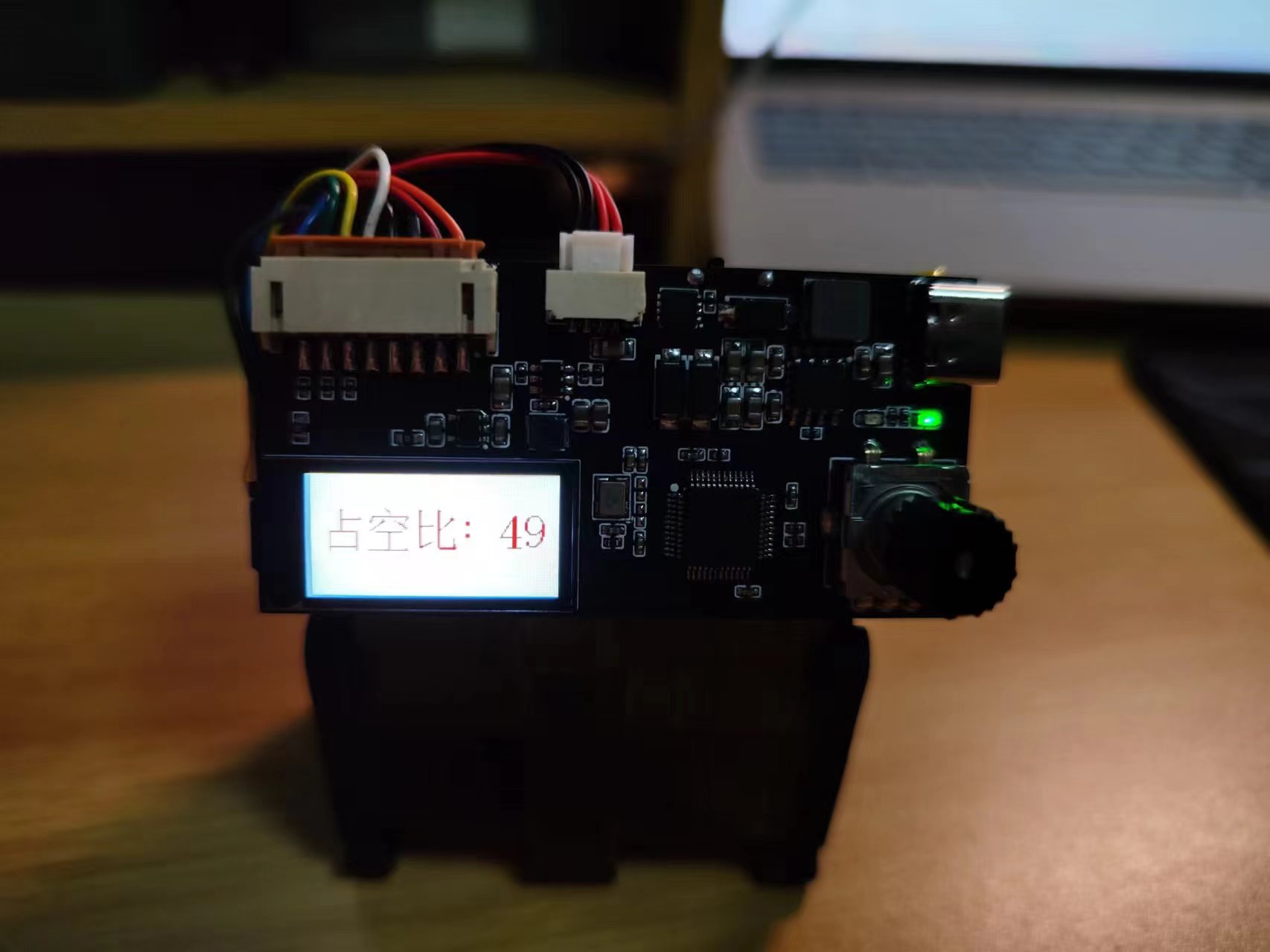
A DIY PWM generator and debugger
: 1. Infinitely adjustable duty cycle via an encoded switch;
2. Real-time duty cycle display on a 0.96-inch LCD screen
; 3. Supports 3-second battery charging and simultaneous charging and use;
4. Power on/off via a DIP switch.
Firmware: https://github.com/linggan17/PWM_Debugger
PDF_PWM_controller.zip
Altium_PWM_controller.zip
PADS_PWM_controller.zip
BOM_PWM_controller.xlsx
94981
[Verified] ESP32S3R8N8 Color Silkscreen Print [Arduino Modified]
[Verified] ESP32S3R8N8 Expansion Board
The ESP32S3R8N8 is SMT-packaged onto an expansion board. The front panel minimizes traces, showcasing the colored silkscreen printing. The top left 4-pin connector is the screen; pin 48 is an indicator light; pins 39 are for the WS2812B BOOT and RST pins, which are not brought out. [Some people like the S3R8N8's appearance, some don't; to avoid it gathering dust, let's create an expansion board with a different color.]
PDF_【Verified】ESP32S3R8N8 Color Silkscreen Printing【Arduino Modified】.zip
Altium_【Verified】ESP32S3R8N8 Color Silkscreen Printing【arduino Modified】.zip
PADS_【Verified】ESP32S3R8N8 Color Silkscreen Printing【Arduino Modified】.zip
94982
Ultrasonic Curve Rangefinder
This is a handheld ranging device that includes ultrasonic sensors, an encoder, an OLED display, power management, and an STM32F103C8T6 microcontroller. This project is used to learn IIC, interrupts, input capture, and the encoder module is very user-friendly; the hardware is easily replicable, and the software engineering will be open-sourced.
I. Project Introduction
This is a handheld ranging device. The input modules are ultrasonic waves and a roller. The roller can move along a curve to provide feedback on the distance along the curve. The display module is an OLED, with an additional laser light to calibrate the position of the ultrasonic measurement. It has a built-in charging and discharging module, and the main controller is an STM32F103C8T6.

II. Project Related Modules
1. Ultrasonic distance measurement, range 2cm-400cm
2. Roller measuring curved distance
3. OLED display
4. Power management, charging and discharging module settings
5. Minimum system design of STM32F103 main controller
III. Application Scenarios
1. Distance measurement
2. Learning embedded hardware and software
IV. Project Completion
Schematic design 100%
complete PCB design 100%
complete Code design 90%
complete 3D shell design 100% complete
V. Soldering Demonstration
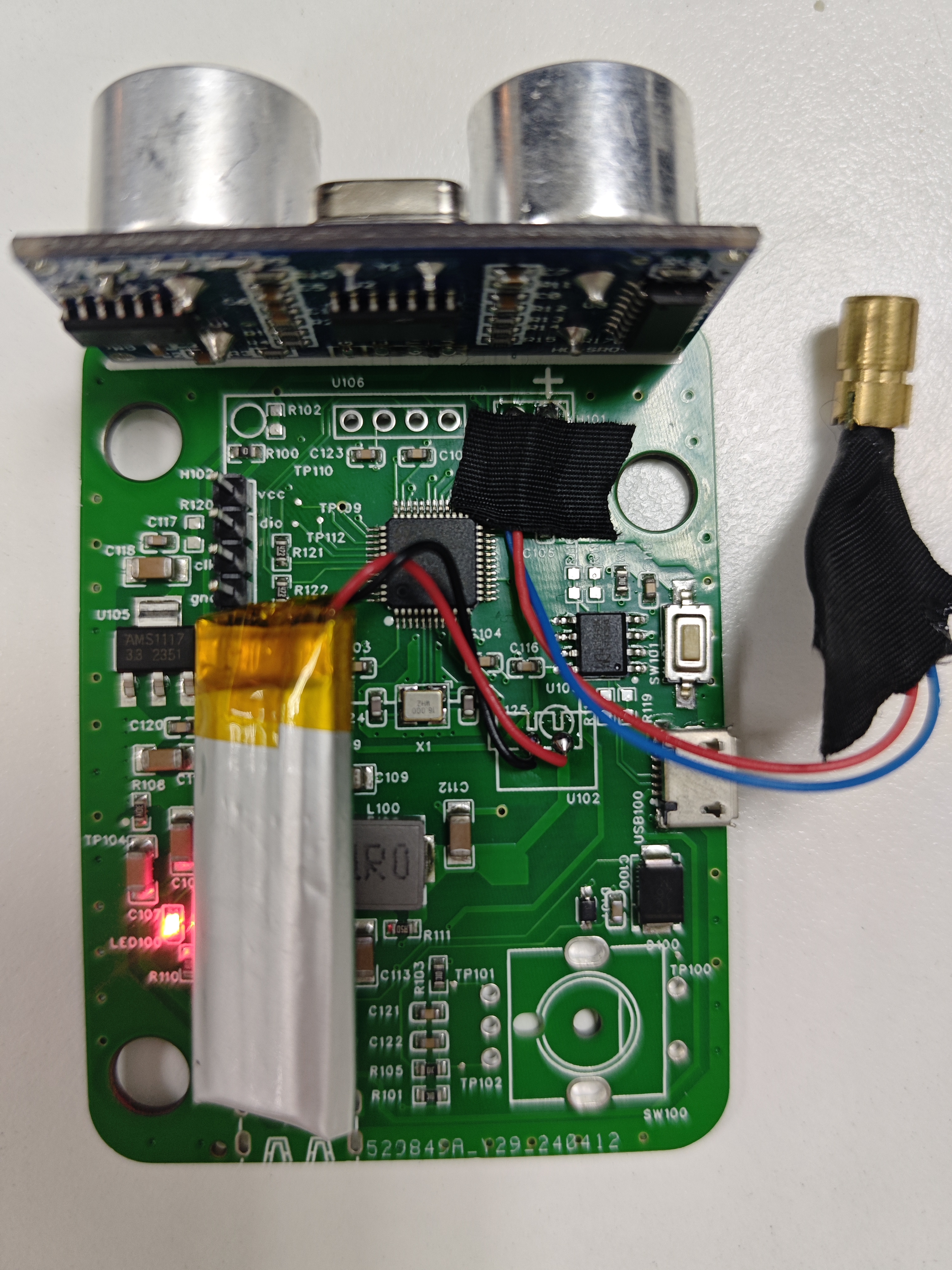
Soldering Notes:
1. The OLED needs to be connected via a jumper wire and mounted to the shell.
2. The outer diameter of the laser light is 6mm. Voltage 3V or 5V is acceptable
. Battery pack dimensions: 50*12*35
mm. Notes:
1. Download the program using the SW interface, which requires J-Link. If you want to download via serial port, you need to modify the BOOT mode.
2. The encoder part of the program sometimes has errors; it may recognize forward rotation as reverse rotation. (I'm a beginner with programming, so the bugs haven't been fixed yet.)
Demo video:
[Radarmeter] https://www.bilibili.com/video/BV1QZ421n75C/?share_source=copy_web&vd_source=8f96cfa2f7d34667a143664dd03d7280
program.zip
3D files.zip
PDF_Ultrasonic Curve Rangefinder.zip
Altium_Ultrasonic and Curve Distance Meter.zip
PADS_Ultrasonic Curve Rangefinder.zip
BOM_Ultrasonic Curve Rangefinder.xlsx
94983
Bomb Pi Zero
A smaller version of the
original H616 development board project, modified from Yuzuki Chameleon's work: https://oshwhub.com/gloomyghost/yuzukih616
Thanks to the developer for the open source! This is a smaller version of the original H616 development board project based on Yuzuki Chameleon: https://oshwhub.com/gloomyghost/yuzukih616.
The Bomb Pi Zero
completely redesigns and relayouts the PCB to reduce its size and adapt to JLCPCB's through-hole technology.
To further reduce size, the eMMC is placed on the back.
The GPIO pin definitions are silkscreened on the back.
There is no copper around the screw holes, so there's no need to worry about soldering (the copper pillars won't connect to GND).
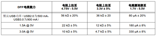
The CC pin resistor of the Type-C port has also been modified. The original circuit might have issues when using CC lines or cables with E-mark.
Other circuits remain unchanged and function identically. The initial version of

V1.0 could not be programmed for unknown reasons. Thank you, Ling.

PDF_Bomb Pi Zero.zip
Altium_Bomb Pi Zero.zip
PADS_Bomb Pi Zero.zip
94984
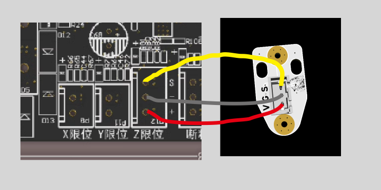
Klicky 3D printer magnetic probe
3D printer probe
Reference project addresses: https://euclidprobe.github.io/cheap
magnets 6x3 with 3mm countersunk holes (N25) (not recommended, you might find 3.6mm inner holes)
https://item.taobao.com/item.htm?_u=m2jk0vj06b22&id=677223530485&spm=a1z09.2.0.0.76042e8dFux8uT
better magnets 6x3 with 2mm countersunk holes (N35)
https://item.taobao.com/item.htm?_u=c2jk0vj07530&id=564130787836&spm=a1z09.2.0.0.2b762e8dpNwhr6
stronger magnets 6x3 with 2mm countersunk holes (N52)
https://item.taobao.com/item.htm?app=chrome&bxsign=scdI4jZwgweQJxe7DKUhjPhlSGEgq80cXj_ry7_K4EmcqG7KSOfez4wRH6t5lfJz4jHQqNMzqastVM0M--OIteZFcqz7IZYnzUR0yj0jJ_dDRtfPkHlMJReSCXTXvpleI jB&cpp=1&id=692502462669&price=0.45-205&shareUniqueId=26392620501&share_crt_v=1&shareurl=t rue&short_name=h.gbXn1d0qaovUOWg&skuId=5275772107137&sourceType=item,item&sp_tk=TW9aRFdJdk ZtQVc=&spm=a2159r.13376460.0.0&suid=2789ab31-2122-4e9b-bb3c-04a9956f3d8b&tbSocialPopKey=sh areItem&tk=MoZDWIvFmAW&un=09603feadf49d3dcb2f10b56166a698d&un_site=0&ut_sk=1.YvxmZCNpDp0DA I6w6OL4SdMC_21646297_1713960094240.Copy.1https://item.taobao.com/item.htm?id=745674021802&skuId=5465764879434&spm=a1z0d.6639537/tb.1997196601.270.296774841W2NCW
Recommended by a pro: supposedly high-precision 6x3 hole 2mm magnet. Countersunk (N52)
https://item.taobao.com/item.htm?id=745674021802&skuId=5465764879434&spm=a1z0d.6639537/tb.1997196601.270.296774841W2NCW
Small head screw M2X4 3mm head (not suitable for cheap magnets)
https://detail.tmall.com/item.htm?_u=c2jk0vj0c3d0&id=717467816792&spm=a1z09.2.0.0.2b762e8dpNwhr6
Countersunk head screw M2x4 3.5mm head (suitable for cheap magnets) (If your magnet has a 3.6mm inner hole, this screw will not work)
https://detail.tmall.com/item.htm?abbucket=18&id=640310583202&rn=f9d09ca2fc4d245e32db9cb892f4f1bb&skuId=5518857014336&spm=a1z10.3-b.w4011-22615119255.94.1239f5e5sapn93
TTC micro switches
: https://item.taobao.com/item.htm?_u=c2jk0vj0710f&id=705433676474&skuId=5270176938209&spm=a1z09.2.0.0.2b762e8dpNwhr6
Omron micro switches
: https://item.taobao.com/item.htm?id=574796579888&spm=a1z0d.6639537/tb2.1997196601.183.483e7484YZPJ9s
SMTSO-M2-0.5ET surface mount nuts for version 6.3 The link provided
(https://item.taobao.com/item.htm?spm=a1z0d.6639537/tb2.1997196601.3.bc637484UYbuhc&id=636483838062
) lists 0603 surface mount resistors. (For 5V standard brightness, choose 0.51K; for 5V high brightness, choose 0.33K; for 24V high brightness, choose 2.4K; for 24V standard brightness, choose 4.7K).
The LEDs used are 0805 surface mount LEDs. A soldering station is available to mount 1206 LEDs. The dual-color white LED uses 1206 (brighter!).
A dual-color version has been added (one LED is always on, and the other is mounted on the lower PCB and lights up, turning off when triggered).
Because of feedback regarding mounting hole placement errors, version V5.4 changed the mounting holes to oblong holes.
A good design was seen on Douyin, so version V5.5 changed the connector pads to XH2.54/PH2.0 universal pads (two pads stacked together).
A new version 6.2 with a step-down circuit has been added. This product
uses an SOT23 packaged LDO voltage regulator chip,
with a jumper added to switch between always-on and triggered LED operation.
A Schottky diode is added for protection (this may cause MCUs with an I/O voltage of 3.3V to malfunction).
For PCB testing
of the voltage regulator chip, please refer to: https://item.taobao.com/item.htm?_u=i2jk0vj0854b&id=643357241091&spm=a1z09.2.0.0.6e582e8dCA7CCG.
Version 6.3 removed the never-used Zener transistor
thread and uses a surface-mount nut.
Version V7.xx
added a version without the "soul" (LED), making it simpler to build.
Please indicate the open-source address or the group number below when selling
. After all, I only created this to increase the number of group members.
Group: 701827620

Version 5.5 3D model.step
klicky V6.2 BOM table.xlsx
klicky adjustable stand.zip
PDF_klicky 3D printer magnetic probe.zip
Altium_klicky 3D printer magnetic probe.zip
PADS_klicky 3D printer magnetic probe.zip
BOM_klicky 3D printer magnetic probe.xlsx
94985
Lower layer Arduino surface mount
The power supply PCB board can output 12V and 5V, with a maximum current of 2A for the 5V output. It can be made to be mounted on a microcontroller; currently, it's used for Arduino surface mount technology.
The power supply PCB board can output 12V and 5V, with a maximum current of 1A for 5V. It can be made to be mounted on a microcontroller; currently, it's used for Arduino surface mount technology.
PDF_Lower Layer Arduino Patch.zip
Altium_lower-layer Arduino patch.zip
PADS_Lower Layer Arduino Patch.zip
BOM_Lower Layer Arduino Surface Mount.xlsx
94986
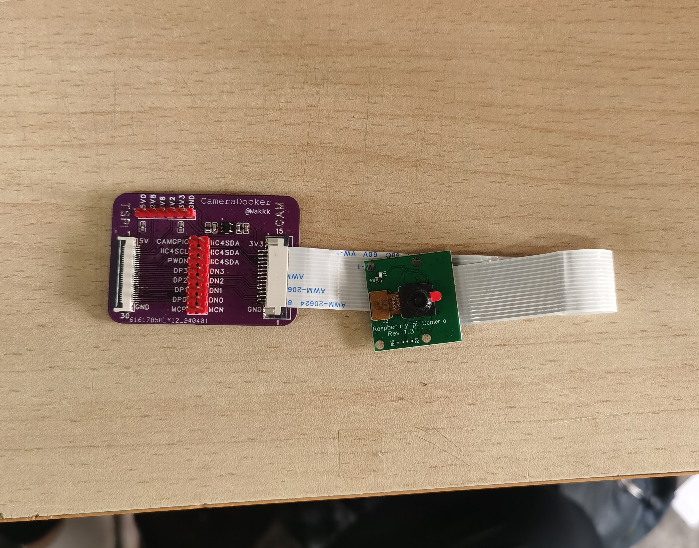
Taishanpai CSI Raspberry Pi Camera Adapter Board
Raspberry Pi camera 0V5647 and Taishanpai CSI interface adapter board
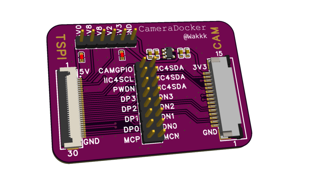
The other power supplies for the Taishanpai CSI interface are brought out for debugging purposes.
All data lines are brought out for debugging
from the 5V system power supply to output 3V3.
PDF_Taishanpai CSI Raspberry Pi Camera Adapter Board.zip
Altium_Taishanpai CSI Raspberry Pi Camera Adapter Board.zip
PADS_Taishanpai CSI Raspberry Pi Camera Adapter Board.zip
BOM_Taishanpai CSI Raspberry Pi Camera Adapter Board.xlsx
94987
electronic


 京公网安备 11010802033920号

 HLMP-ED55-JN400


