Foreword:
April 25, 2024. New 3D shell files have been updated in the attachment.
I. Introduction:
Thank you JLCPCB for providing this opportunity for beginners to learn about electronics!
Thank you JLCPCB for the detailed tutorials and documentation!
Thank you JLCPCB for the ¥20 3D coupon, ¥50 consumables coupon, and ¥30 3D coupon!
This open-source project description includes:
【I. Introduction】
【II. Project Description (Components, Functions, References)】
【III. My Understanding and Precautions】
【IV. Replication Suggestions and Problem Solving】
【V. Code Analysis】
【VI. Improvement Directions (Compiled by a beginner, please refrain from criticism by experts)】
【VII. Attachment Directory】
【Design Drawings (Schematic Diagram and PCB Diagram)】
【Attachments】 (Attachments include the original source code project, my richly annotated code, code study notes, 3D files, schematic diagrams, demonstration videos (with and without casing)...)
II. Project Description:
【Note: As a beginner, the hardware and software parts of this project are almost completely replicated from the official LCSC project.】
1. Main Components:
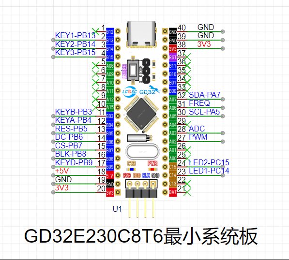
GD32E230C8T6 minimum system board, baseboard, and 1.8-inch TFT color screen. See the BOM below for other components.
2. Final Function:
Can be used to measure the waveform, voltage, and frequency of simple signals.
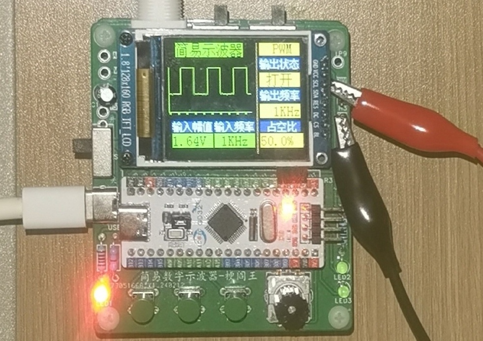
2-1. Screen waveform and parameter display function
(1) Screen display waveform [Note that the waveform is displayed in reverse phase]
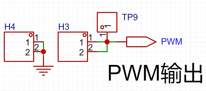
(2) Output signal parameter display (specifically PWM square wave)
Output status [Off/On]
Output frequency [1kHz, 2kHz, 4kHz]
Duty cycle
(3) Input signal parameter display
Input amplitude [Range: -1.6V~5V] (Because it is best not to use 1/50 attenuation in practice)
Input frequency [Theoretical measurable range: 1kHz~10kHz]
2-2. Human-computer interaction: Adjust waveform display and parameter function
(1) [Button KEY1] (left button)
Each press increases the square wave duty cycle in 5% steps, and it returns to 0% when it reaches 100%.
(2) [Button KEY2] (middle button)
controls the output and stop of the PWM square wave. Press once to turn it on, press again to turn it off.
(3) [Button KEY3] (right button)
switches the output frequency of the PWM square wave. Pressing it will cycle through 1Hz, 2Hz, and 4Hz.
(4) [Encoder] (lower right corner)
Pressing it will fix the waveform;
rotating the encoder clockwise will widen the waveform;
rotating the encoder counterclockwise will narrow the waveform.
3. Other
power supply: 5V DC
power supply interface: type-c
probe type: BNC to alligator clip
4. Reference materials (JLCEC official) (very important):
(1) Detailed open source documentation: (The "open source documentation" mentioned later refers to this)
https://www.yuque.com/wldz/jlceda/dso
(2) Free recorded courses on Bilibili:
Search for UP master: LCEC EDA, and view a series of videos from early 2004. This complements the open source documentation tutorial.
(3) Official reference code (code for each part, and the final code)
https://gitee.com/chen11232/GD32E230-Oscilloscope
[The attachment contains the original official final code project, as well as a version of the code project that I have added many comments to, which can be downloaded directly]
I suggest that beginners like me watch the open source documentation and the Bilibili recorded course together, because the official open source documentation includes [hardware design] and [software development], covering circuit principle analysis, schematic and PCB design, soldering tutorials and step-by-step code construction (I also learned GD32 by the way), which is very detailed.
Therefore, please refer to the official materials for details about this project. The following is not a copy of the official explanation (no matter how well I explain it, it is not as good as the official explanation), but my own understanding as a supplement. For some key points, details encountered and some tips during the replication process, please refer to "My Understanding and Precautions" below.
III. My Understanding and Precautions
[Part 1] Circuit Understanding and Schematic Drawing
(1) I drew almost completely according to the official schematic. All component reference numbers and pin selections and circuit connection methods are the same as the official ones. But at that time I did not know that LCSC EDA could adjust the shape of the schematic library of components such as display screens and test points in the schematic diagram (modification method: schematic diagram -> right-click on the component -> edit the device -> modify the library file), so it was just that the schematic layout was different from the official schematic diagram.
(2) When modifying, if you want to change the library containing two op-amp chips from a rectangle representing the chip to two triangles representing the op-amps, please refer to the official Bilibili video (BV number: BV1jy421i7Ji) (around 16 minutes and 27 seconds)
(3) After modifying the library, the new library is saved in "engineering library" instead of "system library"
(4) If you want to find the component description, you can click Place -> Component -> Enter number -> View PDF description in LCSC Professional Edition
(5) The automatic labeling steps can be viewed (BV number: BV1jy421i7Ji) (around 1 hour, 15 minutes and 31 seconds)
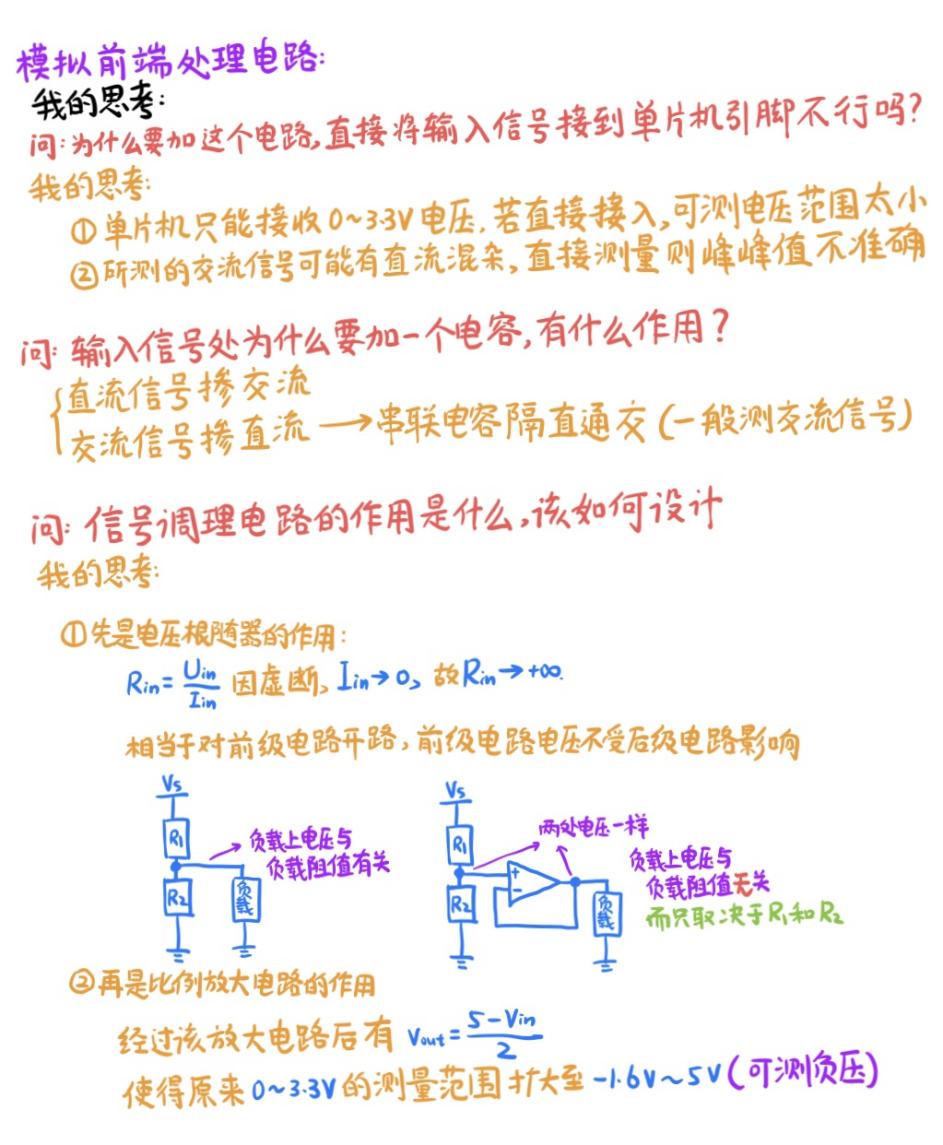
1. Analog front-end processing circuit
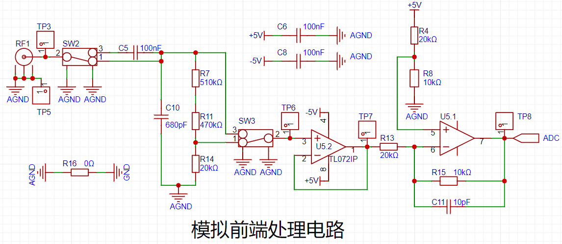

The official raised three questions before explaining the circuit. The following are the corresponding thoughts during the replication process:

Note! The output of the "comparator frequency measurement circuit" op-amp should preferably be equipped with a 1k ohm pull-up resistor because it is an open-drain output.
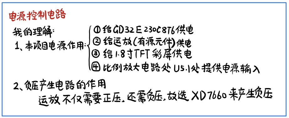
2. Power control circuit
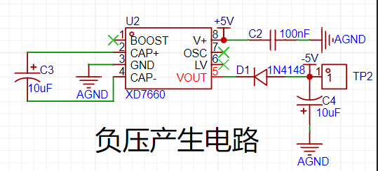
The following is my understanding:
Note!!
The electrolytic capacitor at -5V and AGND in the "negative voltage generation circuit" should have its positive terminal at AGND and its negative terminal at -5V. Note that reversed electrolytic capacitor connection can easily cause the board to explode!
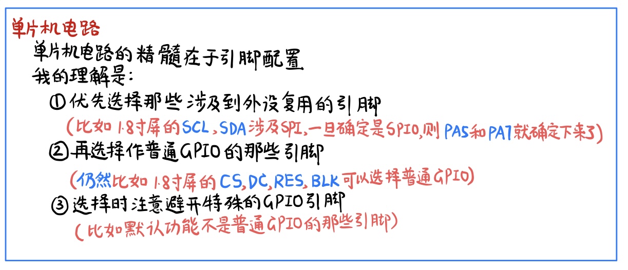
3. Microcontroller circuit
4. Human-computer interaction circuit


When drawing the schematic diagram, please note that there are some minor errors in the schematic diagram part of the Bilibili recorded course. Please see the corresponding comment section on Bilibili for details.
【Part 2】PCB drawing
(1) Similar to the schematic diagram, I drew it almost entirely according to the official schematic diagram. All layouts and traces are almost the same as the official one. Except for the slight difference in layout caused by not adjusting the silkscreen size of a certain capacitor and the pad size of the test point when I drew the PCB before the training camp started, there is no major difference from the official PCB diagram.
(2) When routing the power supply to the chip, the power supply line must first pass through the power supply filter capacitor before entering the chip, instead of just connecting all the +5 or all the +3 power supply lines together.
(3) LCSC EDA does not come with a 3D model of a 1.8-inch TFT color screen. Instead, it needs to be manually bound. The binding method is as follows (BV No.: BV1pF4m1V7bG) (about 11 minutes).
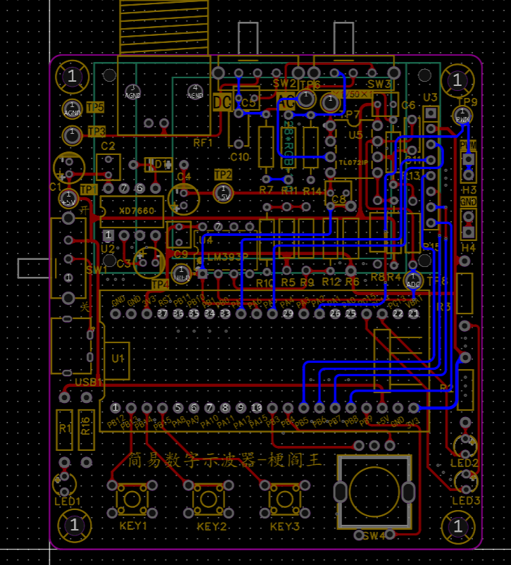
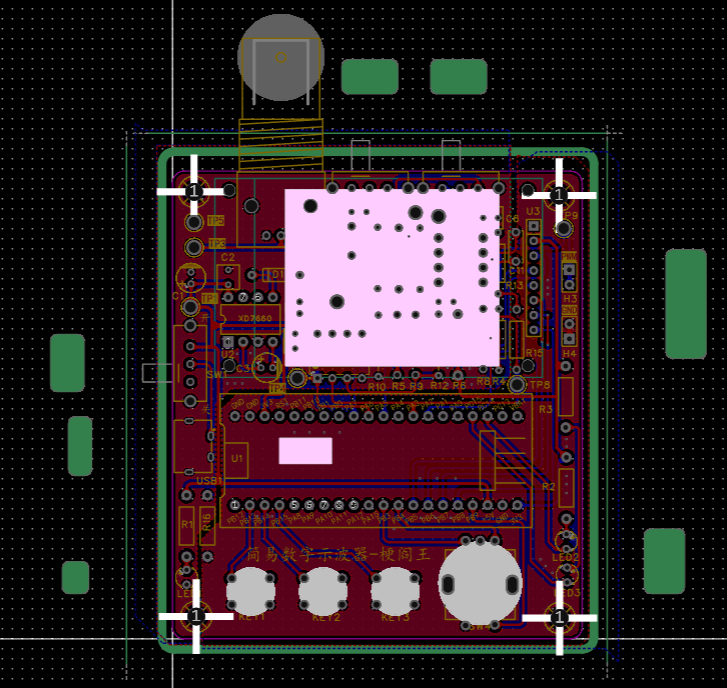
The following are the connection diagrams of the front and back sides of the PCB and the copper pouring situation of the front and back sides.


[Part 3] 3D shell
(1) The 3D shell is not a required step in this project. This step is optional. Use LCSC EDA Professional Edition directly to make it. You can refer to the Bilibili video (BV1d8411S7kF) for a detailed introduction. Here I used JLCSC's 30 yuan 3D coupon, so I only paid for the shipping. I'm giving JLCSC a shout-out.
(2) When making the 3D shell, you must consider whether the top and bottom covers can be put together in reality after receiving the shell. For example, the BNC needs to protrude from the shell. At this time, the side groove needs to be half in the upper shell and half in the lower shell.
(3) The three pictures below are the 3D shell's [border layer] [top layer] [preview]
(4) I have a problem here that I did not consider. My 3D model did not take into account the height of the button, so it will be changed later.


[Part 4] Component purchase
precautions:
When I bought the components, I directly clicked "Place order in LCSC Mall" on the BOM table of the official open source project on the LCSC open source hardware platform and the system automatically imported them without separate selection. However, the official open source project is now offline, so you may need to search for the supplier number in the LCSC Mall yourself. Here, pay attention to the following three items:
(1) 1.8-inch TFT display screen.
This should not be available in the LCSC Mall. When drawing the schematic, the supplier number C9900080251 that I searched for cannot be directly placed in the LCSC Mall. The similar product that I bought was the eight-pin socket corresponding to the display screen...
Just search for the keyword "TFT 1.8 128*160" on Taobao.
(2) M3 and M2 hexagonal posts.
They do not affect the functionality. The M2 hexagonal posts are for fixing the display screen. The M2 hexagonal posts can be used to fix the 3D shell at the four corners. I used copper posts for M2 and nylon posts for M3.
(3) BNC to alligator clip probe.
It is not in the BOM and needs to be purchased in advance. Although it does not affect the schematic diagram and PCB, it is needed to verify the PWM output and display of the oscilloscope.
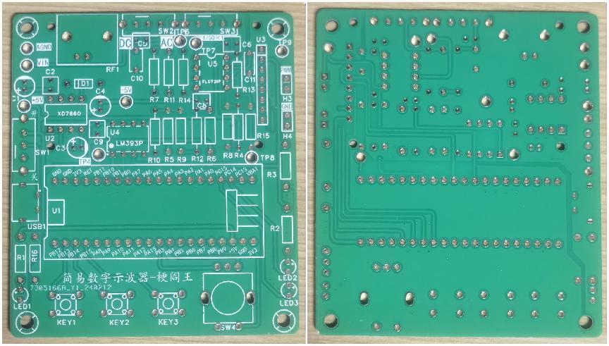
The following are the front and back pictures of the PCB board after it has been made and the situation when the 3D shell is not added:
[Part 5]
Do not pick the wrong resistor when soldering
electrolytic capacitors. Pay attention to the positive and negative
terminals of the chip.
It is recommended to use a knife-edge soldering iron.
See the "Replica Suggestions and Problem Solving" below for details.
How to test the board? Reference (BV No.: BV1sJ4m1Y7Zp (around 45 minutes and 8 seconds)
[Part 6] Burning Code
(1) When downloading the program using GD32 All in One Programmer, if you are directly using LCSC's demo code, you need to compile it first before downloading the hex file, otherwise GD32 All in One Programmer will crash.
(2) Because the code demo in Gitee is constantly being updated, the code displayed on the Bilibili recorded course is different from the demo code in Gitee because the latter version has been updated.
IV. Replicating Suggestions and Problem Solving:
Given that the official documentation and videos are already very detailed, here I will write down my replicating suggestions for beginners like me, as well as the solutions to the problems encountered:
1. Replication Recommendations (Usage of Official Materials):
If you only want to replicate the physical product, theoretically you don't need to understand the circuit principles, but this is one of the essential aspects of this project, so it's best to have some understanding. In addition to the open-source documentation and Bilibili recorded lectures mentioned earlier, I personally recommend combining this with the live replay video "Step-by-Step Guide to Building a Digital Oscilloscope: Hardware Explanation & Q&A" [BV No.: BV1uy421B7Ew] under the "LCSC EDA" account.
For soldering, I recommend watching LCSC EDA's soldering videos on Bilibili first, as videos demonstrate soldering techniques most directly. After watching the videos and memorizing the key points, I suggest checking "1.4 Soldering Practice" in the open-source documentation. The key here is to find a "PCB Soldering Auxiliary Tool" with an HTML extension to minimize soldering errors for beginners.
If you only want to replicate the physical product, you only need to burn the final code in the appendix. For burning instructions, refer to LCSC EDA's official Bilibili course "Project Template Creation" (BV1kw4m1o73g) and the official open-source documentation "2.1". "Development environment setup".
If you want to have a deeper understanding of the code, in addition to learning from the documentation and recorded courses by starting with lighting up an LED, you can download the demo code for each part. It is available on Gitee, the link is at the beginning of this article.
2. Problem solving
The following is about the problems I encountered and their solutions:
(1) Soldering problem
* Resistor soldering error
After ordering directly from LCSC Mall, each component has a supplier number starting with C on its special small bag. When soldering resistors that are easy to get confused, be sure to check the number on the small bag. If you are not sure, you can use a multimeter to measure the resistance value. I made a low-level mistake because of this.
* Forgot to solder the chip socket
This oscilloscope uses three 8-pin chips, which require DIP 8-pin chip sockets when soldering. I only realized after soldering one of them that if the chip is soldered directly, the high temperature during the soldering process may have burned the internal circuit of the chip.
【Solutions to Soldering Errors】JLCIC provides two free board replacements per month, 5 boards each time. So if you don’t mind the board being damaged, you can replace it and resolder it. Otherwise, you can use a desoldering pump. I used a regular manual desoldering pump, which is not troublesome if operated properly. I used two solutions:
the soldering iron was tilted and quickly slid against the soldering error, and the desoldering pump was used to hold the soldering iron
in place to fix the base plate. The soldering iron melted the solder from one side, and the desoldering pump was used to pick up the solder from the other side.
(2) Code Burning Problems
* Problem 1: When following the LCIC EDA Oscilloscope Training Camp video [Software 1], the Software Component is blank at 11 minutes and 14 seconds.
Solution: After checking, I found that the Keil version was too low. Here I chose to follow the tutorial in “2.1 Development Environment Setup” of LCIC’s open source documentation to download the Keil Community Edition.
*Problem 2: The following phenomenon occurs:
After burning the Demo9-screen display experiment code, the bottom and right edges of the screen have several rows of randomly colored dots, but this does not affect the functionality.
Solution: After repeated verification based on the Demo9 code, it was finally found that my screen installation was offset. To achieve the intended effect, the x-coordinate value needs to be increased by 1 and the y-coordinate value by 2. That is, the full screen coverage is not from (0,0) to (160,128), but from (1,2) to (161,130).
*Problem 3: The following phenomenon occurs:
After burning the Demo8 input capture experiment code, the voltage of the PWM 1×2P pin header was measured to be almost 0V. Furthermore, after burning the code for the final case, a multimeter measurement showed that the PWM 1×2P pin header was outputting, but the screen only displayed the interface without showing the waveform.
Solution: I was prepared to resolder the board, but the final solution was surprisingly simple: a multimeter measurement revealed that the voltage was interrupted at SW3, and adjusting it a few times fixed the problem. (i.e., the new switch may need to be toggled several times to turn on)
(3) Open source project display issues

* Problem 1:
As shown in the figure, in the open source project to be released, only the PCB part of the [Design Drawing] section is loaded, but the schematic part is not loaded.
Solution: It is very simple. Re-edit the text description and save it as a draft to refresh it.
* Problem 2:
The PCB part of the released project in the [Design Drawing] section is not displayed as the top layer, but as a 3D layer. I opened the project, readjusted it to the top layer, and exited, but it still displayed as a 3D layer.
Solution: It is very simple. I found that the number of layers displayed in the [Design Drawing] section depends on the number of layers of the last edit of the PCB. Therefore, I moved one pad on the top layer and then moved it back to solve the problem.
V. Code analysis:
(1) For simply replicating the project, it is enough for the code to run normally, but I want to go further and understand the code.
(2) Although I do not have the ability to modify the code now, I can gradually understand it.
The following is a partial analysis:
See the "I Added Rich Comments - Official Final Code Project" in the project attachments for more detailed comments on
the main.c, main.h, led.c
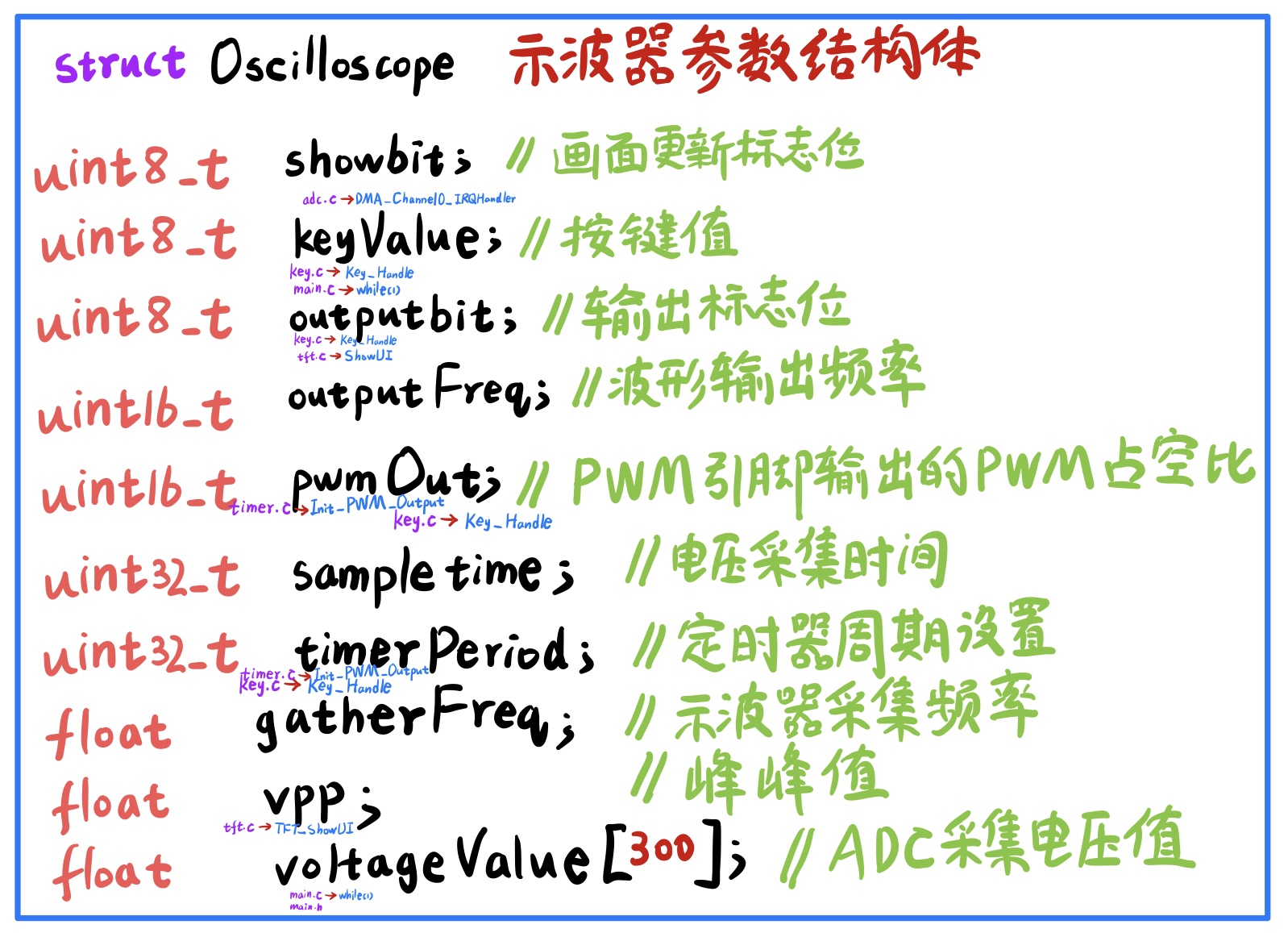
, and led.h files.
The official final example code defines the initialization and switching functions for the two green LEDs, but they are not used yet; we will add functionality to them.
The usart.c and usart.h files
in the official final example code do not seem to directly use the serial port; it is likely used for debugging during the process. The images accompanying
the tft_init.c and tft_init.h files
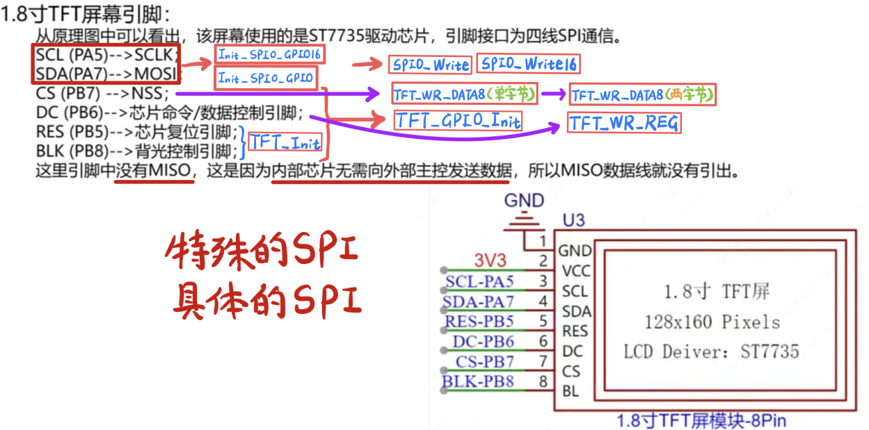
are screenshots from the Bilibili EDA recording course video PPT with my annotations.
For ease of understanding, the images illustrate the approximate relationship between the various functions in the tft_init.c file and the six pins of the TFT that need to be programmed.
Compared to the Demo9 code in the recording course "Screen Display Experiment," the final tft_init.c code has many more functions with "16" after their names, corresponding to a 16-bit data width for SPI0. For example, Init_SPI0_GPIO16 compared to Init_SPI0_GPIO only changes the data width from 8 bits to 16 bits.
The key.c and key.h files
mainly handle three tactile buttons and one rotary encoder.
The keyValue variable in the key.c file is not the same as the keyValue variable in the Oscilloscope structure in main.h.
The EXTI of all four—the three tactile buttons and the rotary encoder—is triggered by a rising edge, while the default level is high, indicating that the trigger occurs the instant the button is released after being pressed.
The interrupt sources configured for Init_Key_GPIO and Init_EC11_GPIO are both EXTI4_15_IRQn, which are exactly PB4, PB9, PB13, PB14, and PB15. The PB4 interrupt is triggered by the rotation of the rotary encoder, while the latter four are triggered by the grounding
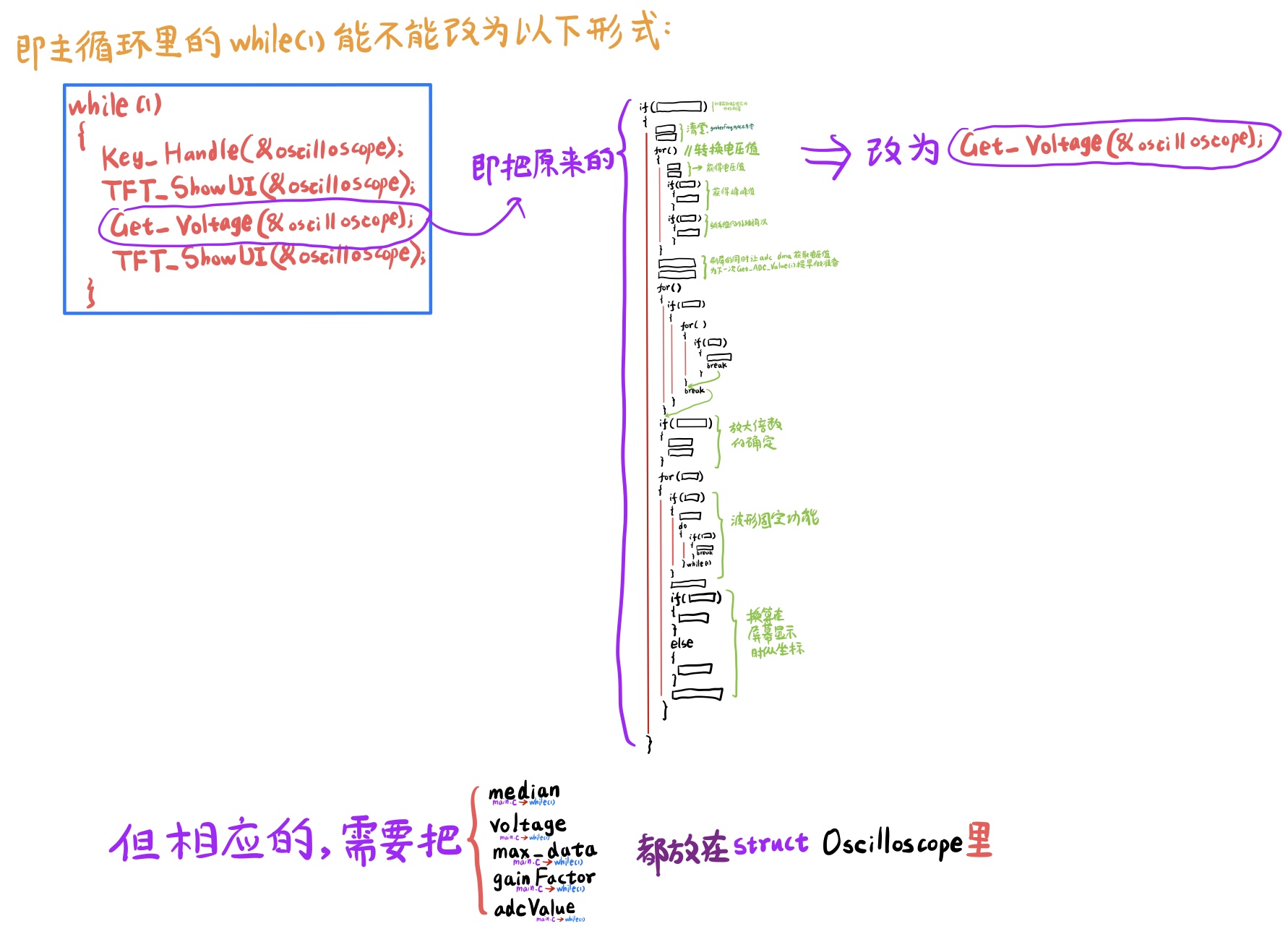
key_Handle function. Each time, the key_Handle function is called first in the while(1) of main.c, and then the voltage acquisition and display steps are performed.
The freq.c and freq.h files
use the general-purpose timer2 to capture the pre-processed signal that is about to be acquired by the ADC. The frequency
division factor setting is very important. According to the official Bilibili recorded course PPT, the clock frequency of the timer used for input capture should be 10 to 100 times the frequency of the signal being measured. The frequency of the input PWM wave here is 1kHz to 4kHz, calculated according to not more than 100 times 1kHz and not less than 10 times 4kHz. The clock frequency of timer2 should be between 4kHz and 100kHz. In the official final code, the divider factor of timer2 is 719, that is, the counting frequency (72M/720) = 100_000Hz = 100kHz, which is exactly the highest value. For
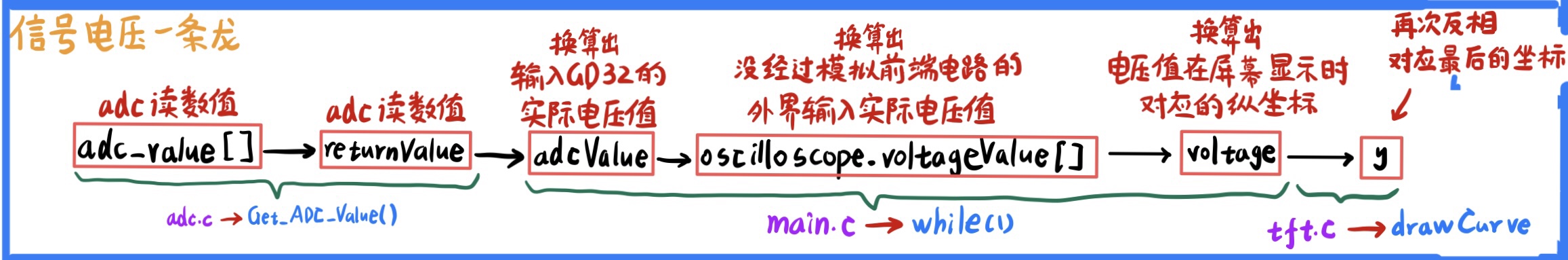
the adc.c and adc.h files
, the Get_ADC_Value function is worth noting. It is responsible for retrieving the data obtained by ADC and DMA from the specified memory area.
It is also important to note the interrupt service function DMA_Channel0_IRQHandler:
after DMA has acquired 300 numbers and entered the interrupt, it will temporarily close the channel and will only reopen it after all the ADC values have been read.
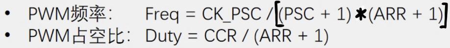
The timer.c and timer.h files
use a general-purpose timer, timer14, to output a PWM wave. The most important formula here is:

The tft.c and tft.h files
contain three important functions: drawCurve, TFT_StaticUI, and TFT_ShowUI.
Regarding TFT_StaticUI, note the following
: A comparison: The "PWM" text in the upper right corner (yellow background, black text) and the "duty cycle" text in the lower right corner (purple background, white text) both belong to static UIs where the bottom bar is wider than the characters, but they are handled differently.
For the former: `
sprintf(showData," PWM ");` //This means pre-leaving spaces before and after PWM.
`TFT_ShowString(110,0,(uint8_t*)showData,BLACK,YELLOW,16,0);
memset(showData,0,32);`
For the latter:
`sprintf(showData," // That is, first a space, then display the duty cycle in ShowChinese.
TFT_ShowString(110,92,(uint8_t *)showData,WHITE,PURPLE,12,0);
memset(showData,0,32);
TFT_ShowChinese(118,92,(uint8_t *)"duty cycle",WHITE,PURPLE,12,0);
The difference between the two is that the former uses English letters, while the latter uses Chinese characters. Therefore, the former can be directly printed using sprintf, but the latter cannot.
Because my screen offset requires adding 1 to the x-coordinate value and 2 to the y-coordinate value, the display of the "simple oscilloscope" and the related code of the leftmost vertical axis of the screen have been slightly adjusted in terms of coordinates.
For TFT_ShowUI, please note the following:
For digital displays, the following three functions are generally used together: sprintf(showData,"%3.0fHz ",(*value).gatherFreq), TFT_ShowString, and memset2.
For Chinese character displays, use TFT_ShowChinese directly.
A minor error in the official final example code (as of March 20th):
In the initialization comments of main.c, the black fill was written as white fill.
The last two functions in adc.h are declared but not used; this is likely because they were forgotten to be deleted during code merging and modification.
In the tft.init.c function Init_SPI0_GPIO16:
SPI_TRANSMODE_BDTRANSMIT should correspond to bidirectional mode, but the comment is incorrectly set to "two-wire unidirectional full-duplex mode" because the function Init_SPI0_GPIO above...
SPI_TRANSMODE_BDTRANSMIT is a single-wire bidirectional half-duplex transmission mode;
and Init_SPI0_GPIO16 is just a change from 8-bit data width to 16-bit data width compared to Init_SPI0_GPIO, but the corresponding structure variable is still marked as 8 bits in the comments. VI
. Improvement Directions (Summary for Beginners, Please Don't Criticize)
Although I am a beginner, I have a desire to improve (not really).
Although I am not capable of making improvements now, I can prepare
the following improvement points in advance. These are basically collected from the official Bilibili recorded course and the discussions I have seen in the group.
[Functional Improvement]
(1) The oscilloscope is changed from a single channel to a dual channel or even a multi-channel.
(2) Add a signal generator function. At this time, in addition to the minimum system board, an external DAC module is also required.
[Circuit Improvement]
(1) Improvement of input signal attenuation circuit: ×1/50 attenuation is not practical for this project because for voltages of 5V~25V, using ×1 will exceed the limit, and using ×1/50 will attenuate to 0.1~0.5V, making it susceptible to interference and inaccurate. It can be adjusted to 1/3, that is, the resistance values of the three voltage divider resistors in the corresponding circuit (analog front-end processing circuit -> voltage attenuation circuit) can be adjusted by yourself. (However, the sum of the resistance values of the three resistors needs to exceed 1MΩ)
(2) Improvement of signal conditioning -> proportional amplifier circuit: The relationship between Vout and Vin can be changed by adjusting the resistance values (but the resistance values still need to meet certain constraints after adjustment)
(3) Improvement of comparator frequency measurement circuit: The threshold voltage U+ of the hysteresis comparator can be made higher and U- lower by adjusting the resistance values, thereby improving the frequency measurement effect (but the resistance values still need to meet certain constraints after adjustment)
[Schematic diagram improvement]
*If you are not satisfied with the schematic diagram of the component, you can modify it in the library. For example, the LED pattern can be filled with red or green to emphasize the LED color; the test point pattern symbol can be reduced to make the schematic diagram more aesthetically pleasing.
[PCB Improvement]
(1) If you are not satisfied with the PCB layout of the component, you can modify it in the library. For example, the size of the test point pad can be reduced (the multimeter needle can probe in); the capacitor silkscreen border is larger than the actual component size, so it can also be reduced.
(2) When switching between the front and back sides, there can be two vias to enhance the current carrying capacity, but you need to close the wiring -> remove the loop.
[Component Selection Improvement]
Through-hole components become surface mount components. (Each has its advantages and disadvantages)
*Through-hole components are easy for beginners to solder and take up a lot of space;
*Surface mount components take up little space, and soldering requires more than just a soldering iron
. The core board and screen do not need to be socketed. (Each has its advantages and disadvantages)
*The advantage of using a socket header is that both the screen and GD32 are plug-and-play, but it lacks customization.
* Direct integration without a socket header offers sufficient customization, but has lower fault tolerance .
Probe modification:
The original BNC to alligator clip probe can be replaced with a passive probe from a professional oscilloscope. This allows for preliminary signal attenuation using the probe's built-in ×10 range, instead of relying solely on the attenuation circuit.
[Code Improvement]
*When the waveform is fixed, the program directly enters an infinite loop, preventing other operations. For example, pressing a button is ineffective when the waveform is fixed. However, this isn't a major issue; it should be fine without adding new features.
VII. Attachment Directory:
[Original Version - Official Final Code Project] The official final project downloaded from Gitee on March 20th, which I haven't modified.
[My Version with Rich Comments - Official Final Code Project]
[Code Learning Notes] Contains incomplete records; please refer to the included readme for details.
The [3D Shell Package] provides 3D shell files, with file extensions STL, STEP, and OBJ available for immediate use.
The [Illustration Package] contains all the images described herein. The
[Demo Video] is only 20 seconds long and slightly blurry due to the 50MB size limit for each attachment; please understand.
The [Illustration Video with 3D Shell] is only 4 seconds long and serves as proof of the shell's functionality. See the "Demo Video" for a full demonstration of the features.


 京公网安备 11010802033920号

 M3022--110145-035BC


