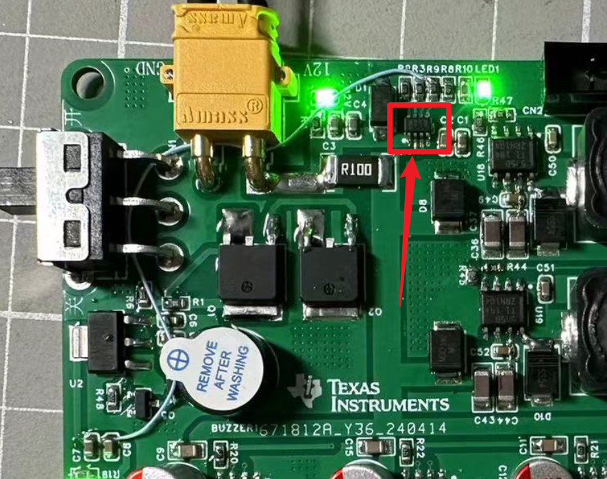
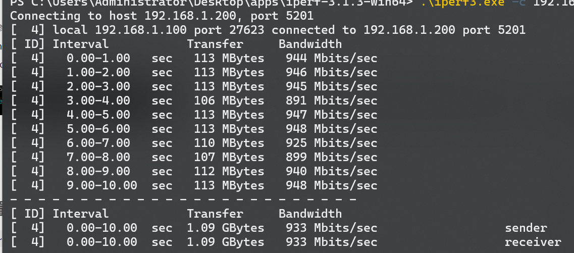
The RTL8367 three-port switch, equipped with two RTL8153B network cards, allows direct USB connection to devices such as mobile phones and thin and light laptops that lack an RJ45 network port. It also provides gigabit speeds via USB 3, with a tested speed of 933Mbps.
Altium 8367 three-port switch with two built-in RTL8153B network cards. (zip file)
PADS_RTL8367 three-port switch with two built-in RTL8153B network cards. zip
The TPA3126 LM1875 quad-channel amplifier adds a bass enhancement chip, NJM2706, and
24V power supply. The first three are Japanese potentiometers, which are a bit expensive, but the last domestic potentiometer is cheap and works well.
For any questions, please leave a message. Recommended purchase links (purchase from other LCSC online stores)
: Original Bluetooth audio module DIY (careful reading to avoid reverse soldering); TPA3126 heatsink (11*5*40mm (20mm hole spacing)); SAM8108 switch chip (LCSC does not have 20K dual-gang switch potentiometer, only one is needed, purchase from other LCSC online stores);
Gold, silver, and black 15*16.5 rotary switch volume control knob caps (4 pieces)
; TO-220 insulating pad silicone heatsink; insulating silicone sheet for LM1875 (100 pieces) (one piece is used when installing the heatsink on the LM1875);
pluggable terminal block spacing 5.08mm (2P);
heatsink 20*15*10mm (silver); high-quality heatsink for LM1875,
commonly used M3 screws and nuts 3*5, 3*8, 3*10, 3*12, 3*12 round head and flat head screws, etc.
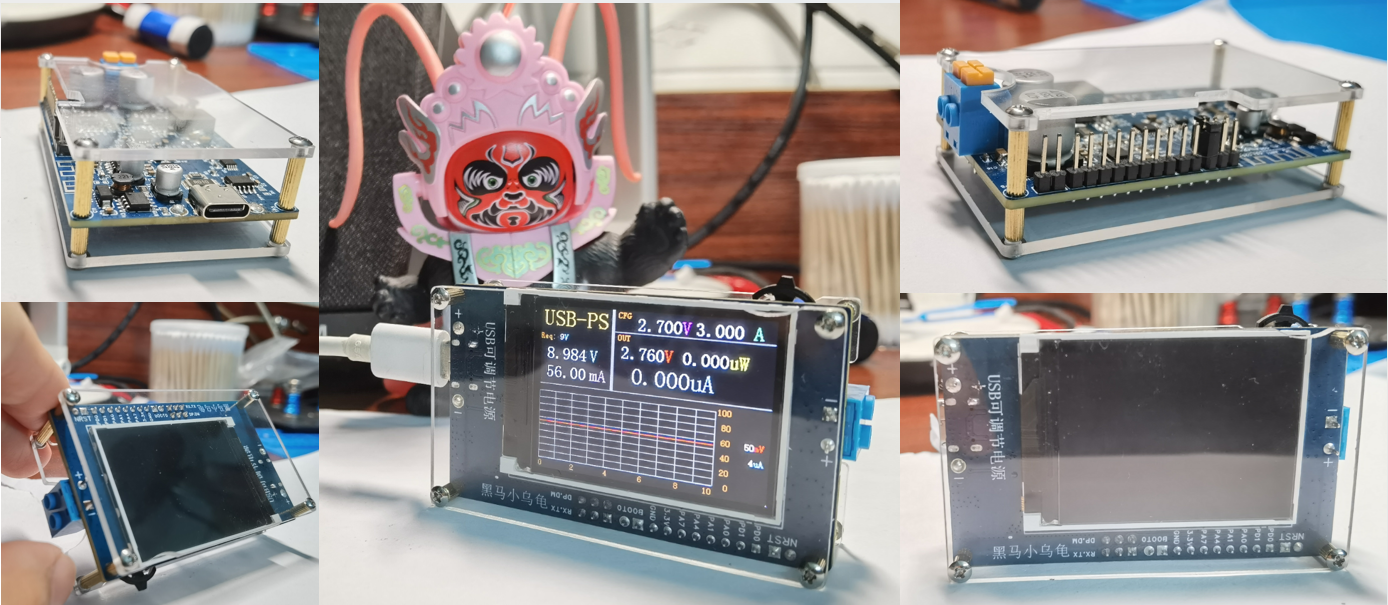
USB programmable power/power consumption monitoring V1.0, controlled by a mini-program, supports USB PD3.0 and BC1.2 protocols, supports 5V~20V input, wide-range output voltage adjustable from 2.7V to 20V, and a 3A load capacity.
Project Introduction
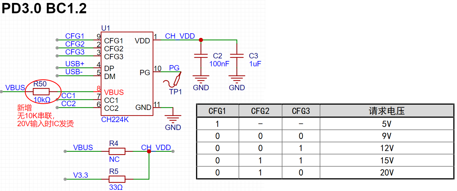
———————————————————————————————————————————————————————————————— This design supports USB PD3.0 and BC1.2 protocols. It can power the system
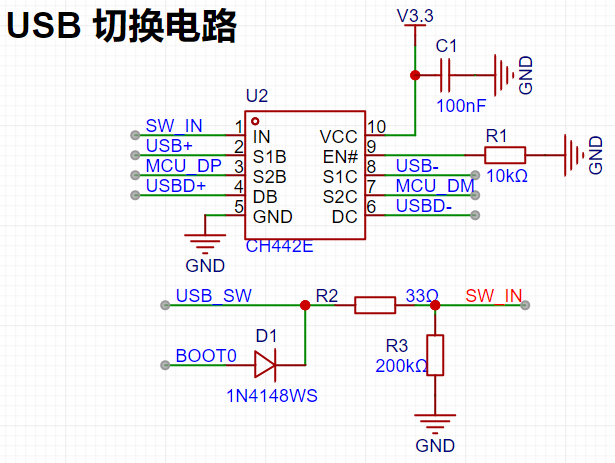
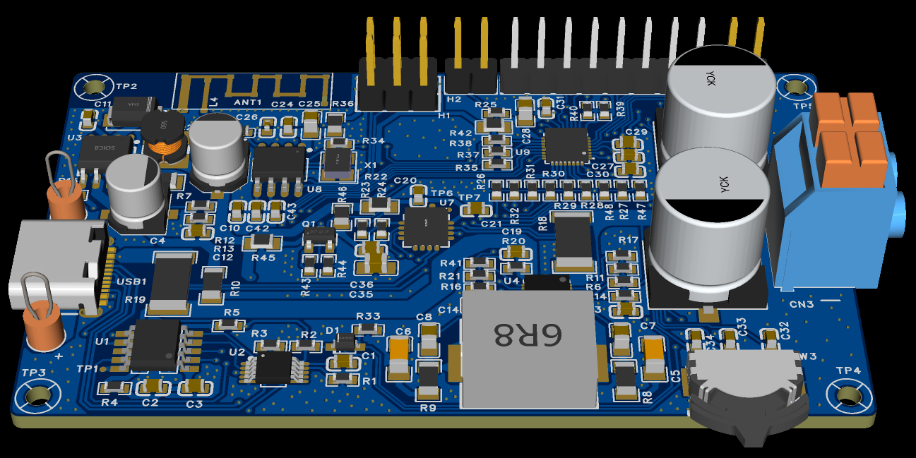
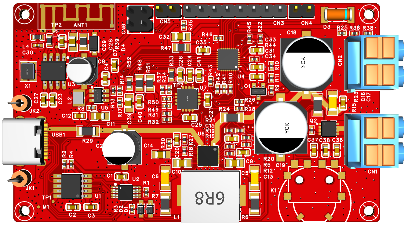
with 5V, 9V, 12V, 15V, and 20V power from USB power adapters supporting the PD/BC1.2 protocol . It features a wide-range output voltage, adjustable from 2.7V to 20V, and a 3A load capacity. Input and output voltage and current are monitored in real time and fed back to the user via a 320x240 TFT screen or a host computer. Output and input voltages can be adjusted via a multi-function button or the host computer. This is an initial version of the project, and there are still some minor hardware design issues, listed at the end. If you wish to replicate this project, it is recommended to work on version V2.0. Below is the open-source address for V2.0. Why retain V1.0? The main reason for keeping version 1.0 here is that some friends have already been working on it. We want to keep version 1.0 here so that they can refer to the relevant information. [Spark Program] USB Programmable Power Supply/Power Monitoring - JLCPCB EDA Open Source Hardware Platform (oshwhub.com) (Click image to view larger image) The host computer WeChat mini-program is now online. You can scan to open the mini-program: Project Background ———————————————————————————————————————————————————————————————— I am an embedded software engineer who likes to tinker. I usually enjoy making some interesting "toys". Since I don't currently have an adjustable power supply, I often use voltage sources such as 12V, 3.3V, 5V, or simulating battery voltage changes when tinkering with my "toys". I don't want to spend money to buy an adjustable power supply. I thought, " Can I make an adjustable power supply that is portable, compact, does not depend on a specific voltage source, and can meet most of my daily needs?" My first thought was, "Can I use an existing power adapter (USB adapter) and connect an external DC to DC chip to achieve step-up and step-down voltage conversion?" I got right to it. I even checked out some open-source projects to see if there were any similar ones I could replicate. But... either they required a fixed input voltage source of 10V or higher (which is pretty impractical; I'd need a separate adapter to use that voltage source, which doesn't meet my design requirements); or the circuitry was too complex, making the whole device bulky, inconvenient to carry, and not suitable for DIY. Fine, I'll have to do it myself! Let's get started... Project Highlights : Supports USB PD3.0/PD2.0, BC1.2 protocol, supports 5V~20V input /output voltage adjustable from 2.7V~20V, 3A output current load capacity, sufficient for daily experimental use. Input/output voltage can be configured via WeChat mini-program. Real-time monitoring of input voltage and current is available for output voltage. Voltage detection resolution is 8mV, current detection resolution is 40uV/10mR=4uA. (320x240) The TFT screen displays real-time power consumption and can be used as a simple power meter to monitor the power consumption of electrical equipment. It can communicate with a host computer via BLE to expand its applications. It requires few peripheral components, has a simple implementation principle, and is very convenient for DIY. It is compact and easy to use, does not rely on a specific power supply, and can be used with any USB adapter. The hardware and software are completely open source . This project can also be used as an entry-level development board. Most peripherals used in embedded systems learning are used in this project, such as I2C, UART, SPI, USB, and IO control. Unused IO ports are brought out. Hardware Introduction ———————————————————————————————————————————————————————————————— Hardware Resources and Dimensions (Click image to view larger image) (Click image to view larger image) Power Output Terminal Block (Click image to view larger image) Here I will focus on explaining why this design chose the output terminal block shown in the figure. The purpose is simple: convenience. It does not rely on a specific connector; any ordinary wire can be used. Moreover, it can be operated without any additional tools (anyone with hands can do it). I've seen some similar open-source projects in the open-source community, but they all use dedicated sockets, which have limitations and don't meet the requirements for portability and convenience. Schematic diagram introduction (click the image below to see a larger version): Below is the power input circuit. The input in this design is divided into two parts: one part is through the USB Type-C port; the other part is through the U10 and U11 terminals connected to a DC power supply. PD protocol chip circuit: This part of the circuit is relatively simple, just the necessary power supply and control circuitry to complete the interaction between the PD protocol and the BC1.2 protocol. Note: The following series resistor for VBUS is not included in this version of the PCB; only the schematic has been updated. Without the 10k series resistor, the PD chip will overheat under 20V power supply, which may damage it over time! USB switching circuit: Used for multiplexing and switching between the PD protocol chip's USB D+, D- and the MCU's USB D+, D-. The working principle is: when powered on, D+ and D- are handed over to the PD protocol chip to complete the BC1.2 protocol interaction; when protocol information interaction is not needed, it can be used as the MCU's external communication USB interface. Additionally, the MCU's firmware is also downloaded through this USB port. A 3.3V DC-DC circuit provides a 3.3V power supply to the system. It supports input voltages from 3.0V to 40V.


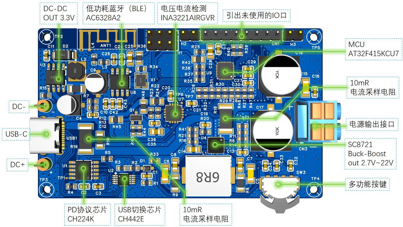


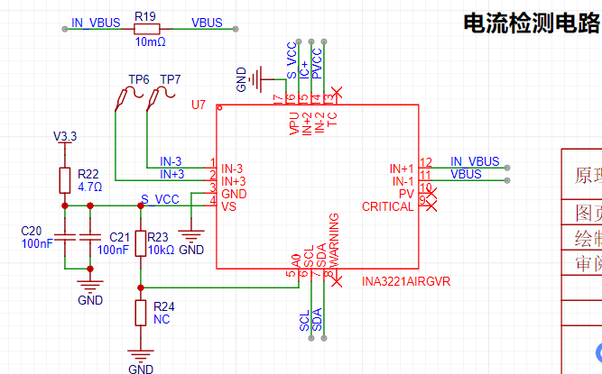
The voltage and current detection circuit uses the INA3221, which supports 3 differential inputs and 3 bus inputs. The differential inputs are typically used to detect
small voltage changes in analog signals, such as current detection. Its ADC is 16-bit, with one sign bit, resulting in a 15-bit actual numerical representation. The LSB
is 40µV, and the full-scale range is 163.8mV. The bus inputs can be used to measure analog signals with lower resolution requirements, such as system input/output voltage detection.
The LSB is 8mV, and the full-scale range is 32.76V.
This design uses IN-1 to detect the VBUS input voltage, and IN+1 and IN-1 to detect the VBUS input current. IN-2 detects the output voltage, and IN+2 and IN-2
detect the output current.
The digital power supply Buck-Boost circuit provides power to the load. Its main function is to provide power to the device based on the user-defined output voltage and current limiting
. The output voltage and current limiting can be configured via the I2C interface.
The circuit in the red box in the diagram below, marked "New," was added during later debugging. This version of the PCB board was not updated; only the schematic was updated. This is important to
note. Currently, components are added using jumper wires. The SC8721 supports input voltages from 2.7V to 22V and converts output voltages from 2.7V to 22V.

The main control MCU circuit includes boot, reset, I/O interfaces, and power supply sections. It's important to note that when burning firmware via USB,
{BOOT1, BOOT0} must be equal to 01 to ensure the CODE boots from the startup program memory. BOOT1 is located on port PB2, which is connected to a
button input with a filter capacitor. When the MCU is powered on, the filter capacitor stores charge. When attempting to enter the startup program, there's a high probability it will fail
and instead enter the RAM program segment. The solution is to simultaneously press and hold SW1 and short the BOOT0 terminal, then reset or power on the MCU.

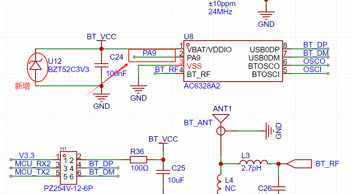
This design also incorporates a Bluetooth Low Energy (BLE) chip. The BLE chip circuitry is shown below, including RF, crystal oscillator, I/O control, and power supply sections.
The BLE chip can be physically connected to the MCU's UART via jumpers, enabling data exchange through the UART port. When downloading the BLE chip firmware,
the jumpers . USB0 DP and DM are used for BLE chip firmware download, or UART TX and RX in normal mode for communication with the MCU.

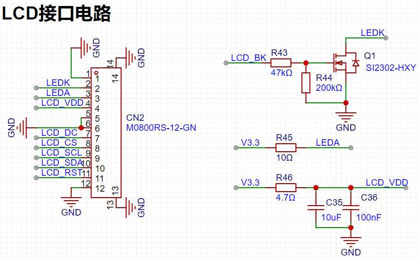
The LCD interface circuit is shown below, consisting of backlight control, power supply, I/O control, and SPI communication circuitry.
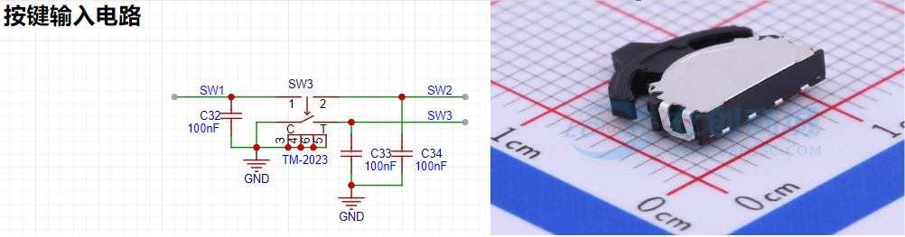
The multi-function button circuit and physical diagram are shown below.
User UI Introduction
: ————————————————————————————————————————————————————————————————————
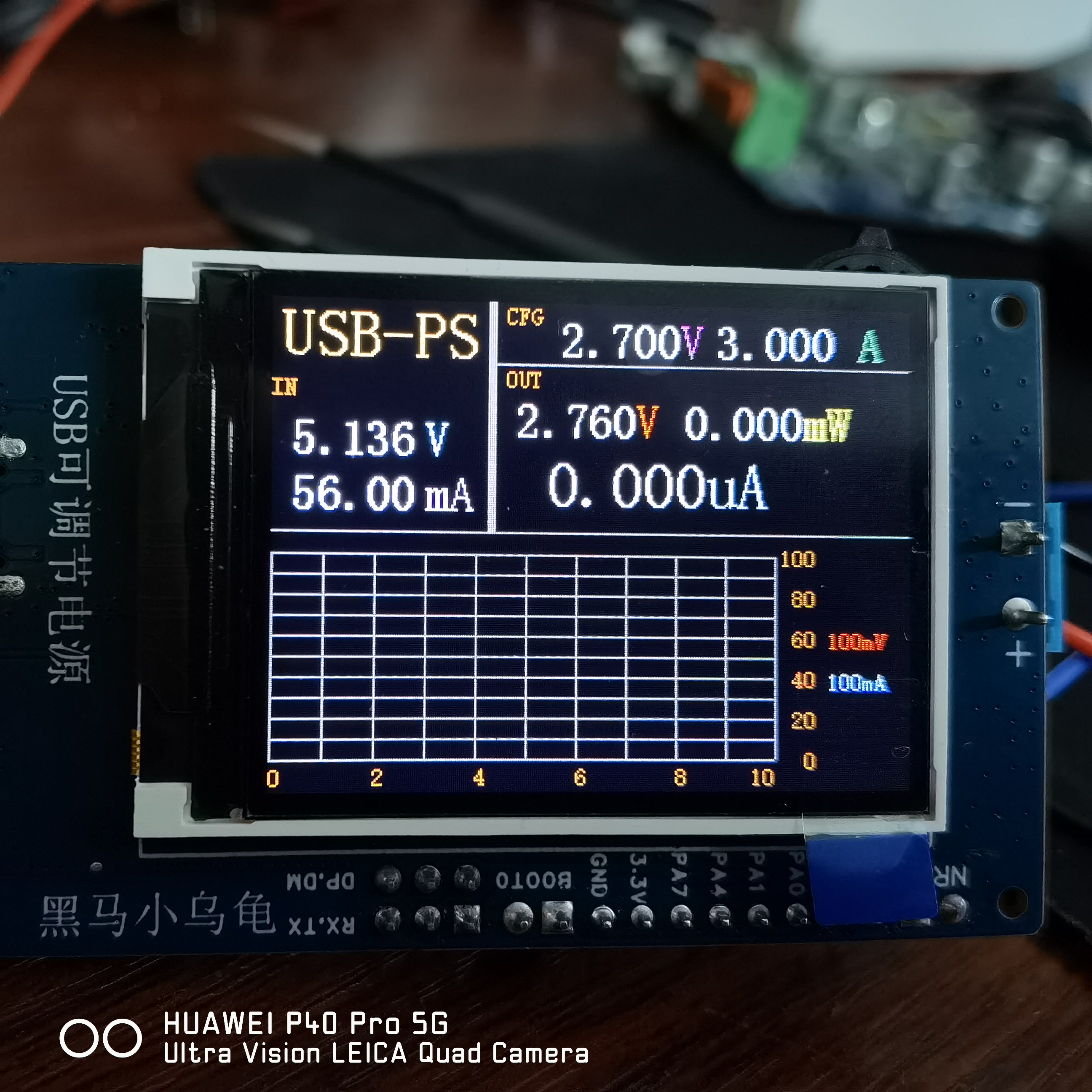
LCD Display Description:

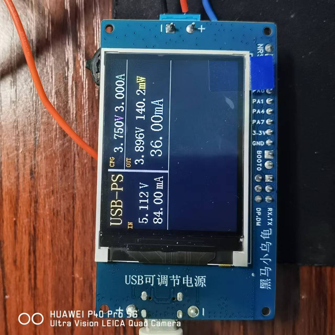
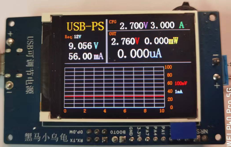
The upper left corner of the LCD displays two pieces of information: 1. It displays the currently set maximum allowed voltage, which is
the maximum allowed voltage requested from the USB power adapter via the PD protocol or BC1.2 protocol; 2. It displays the real-time voltage and current information of the input source.
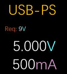
The upper right corner of the LCD displays two pieces of information: 1. 1. Displays the currently set desired output voltage and current limit; 2. Displays the real-time actual output voltage,
current, and power information.
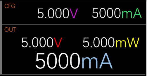
The lower half of the LCD is used to record the output voltage and current information of the most recent 250 sampling points. The red line represents the output voltage, and the light blue line represents the output current. The multi-function button
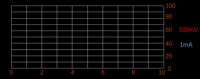
is described
below. It has three degrees of freedom: counter-clockwise rotation, clockwise rotation, and pressing down in the center.
These represent three different buttons. In this project, counter-clockwise rotation is defined as the left button (LEFT), clockwise rotation as the right button (RIGHT), and
the center button as the center button (CENTER).

The table below lists the button events used in this project. Button
Event
Description:
DOWN
(press),
UP
(release),
SINGLE_CLICK
(single click ),
MULTI_CLICK (
multiple clicks, such as double click, triple click, quadruple click, etc. ),
LP
( long press),
VLP (long press), VVLP (extreme long press) , HOLD (press and hold). Button Function Description: Button Name, Prerequisites , Trigger Function , Remarks. CENTER ( Power On) , SINGLE_CLICK ( Enables output voltage and current limiting settings) . When this function is triggered, the corresponding adjustable option will flash. CENTER ( Output Voltage /Current Limit Setting), Enables, SINGLE_CLICK (Toggles selected output voltage and current) . CENTER ( Power On) , MULTI_CLICK=3 (Cyclicly sets PD protocol/or BC1.2 protocol request voltage: 5V->9V->12V->15V->20->5V...... CENTER Power-On State: MULTI_CLICK=4 cycles through turning the voltage and current detection recording function on/off. When powered on, the system will collect voltage and current information from the last 250 points in real time and output it to the LCD screen. LEFT Output Voltage/Current Limit Setting Enabled: SINGLE_CLICK - Output voltage decreases by 50mV. LEFT Output Voltage/Current Limit Setting Enabled: MULTI_CLICK=2 - Output voltage decreases by 100mV. LEFT Output Voltage/Current Limit Setting Enabled: MULTI_CLICK=3 - Output voltage decreases by 1000mV. RIGHT Output Voltage/Current Limit Setting Enabled: SINGLE_CLICK
Output voltage increases by 50mV.
RIGHT
output voltage/current limit setting enabled.
MULTI_CLICK=2
output voltage increases by 100mV.
RIGHT
output voltage/current limit setting enabled.
MULTI_CLICK=3
output voltage increases by 1000mV.
LEFT
output voltage/current limit setting enabled.
HOLD
continuously decreases output voltage
in 50mV steps.
RIGHT
output voltage/current limit setting enabled.
HOLD
continuously increases output voltage
in 50mV steps.
Software Introduction
————————————————————————————————————————————————————————————————
The software architecture used in this project was developed independently. The core of this software architecture is that all functional modules are independently separated, and modules interact with each other via messages
. Each module maintains its own state. The architecture prioritizes functional cohesion and data coupling, minimizing logical coupling or direct modification of each other's data.
The following is a program framework diagram. A brief explanation of some modules follows; for detailed information, please refer to the source code. Feel free to leave comments and discuss any unclear points:
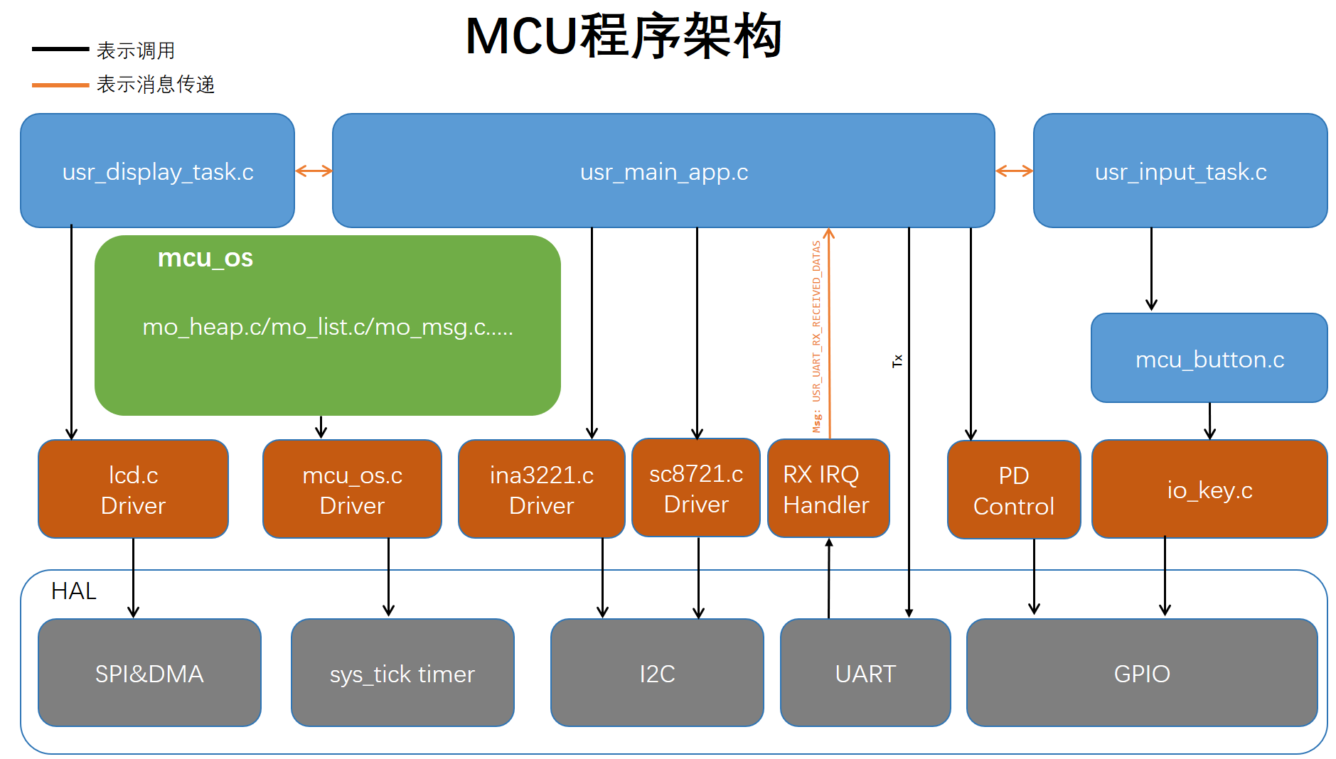
`mcu_os`:
The core is the `mcu_os` part, which implements message processing, task scheduling, memory management, and other functions. The `usr_main_app`, `usr_input_task`, and
`usr_display_task` modules in this project are built upon this foundation for message passing, fulfilling the various functional requirements of the system UI.
`usr_display_task`:
Responsible for receiving status information from `usr_main_app` and displaying it on the LCD screen.
usr_main_app:
Responsible for receiving user input events from usr_input_task, responding to user input events, and sending some status information to usr_display_task.
usr_input_task:
Responsible for calling the driver layer's io_key, reading the io_key status information, generating key events, and sending the key events to usr_main_app.
Main API functions:
static void key_event_handle(mo_key_event_msg_t *k_event): User key event handling
static void display_task_handle(mo_task tsk, mo_msg_id msg_id, mo_msg msg): LCD display event handling
static void uart_rx_msg_handle(mo_u8 *p_dat): Host computer UART RX datagram handling
static void main_task_handle(mo_task tsk, mo_msg_id msg_id, mo_msg msg) msg): Main application event handling; all system event inputs and outputs are received and sent
here .
Firmware Download
————————————————————————————————————————————————————————————————
MCU Firmware Download The
MCU firmware download for this project only requires a USB cable with a USB-C port. Use Artery's USB DFU download tool (Artery_ISP_Programmer). You
can download and install it yourself, or you can find the downloaded "docs" in this directory of the code repository. You also need to install the USB DFU driver
(Artery_DFU_DriverInstall.exe), which is usually located in the download tool's directory.
Before powering on, ensure {BOOT1, BOOT0} = 01 to enter USB DFU mode. BOOT1 (PB2) is currently connected to a clockwise rotating button; keep the button
pressed to the right. BOOT0 has a terminal block; short the two ends together (this is silkscreened on the PCB). Maintain this shorting state during program download, as this
terminal also functions to switch the USB interface to the MCU.
When {BOOT1, BOOT0} = 01, power on the device; it will enter USB DFU mode, as shown in Figure 1. Continue clicking
Next until Figure 2, select the firmware to download, and then click Next to complete the download while the device is off. Power off the device to restore {BOOT1, BOOT0} = 00/10. Power on the device; it should now
function normally.

Bluetooth Low Energy Firmware Download
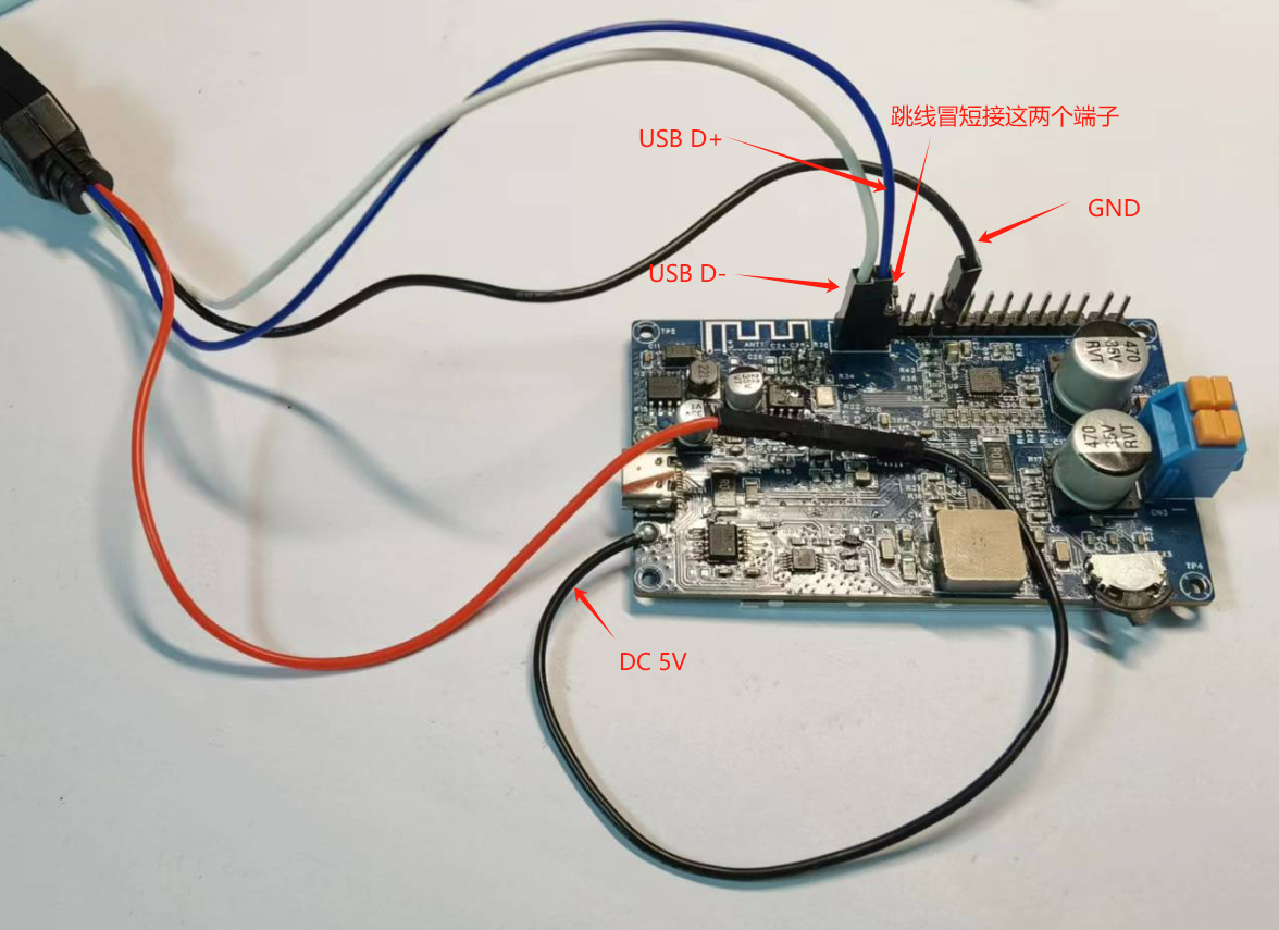
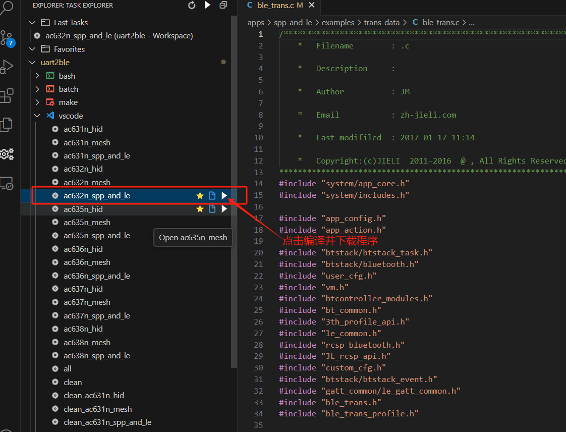
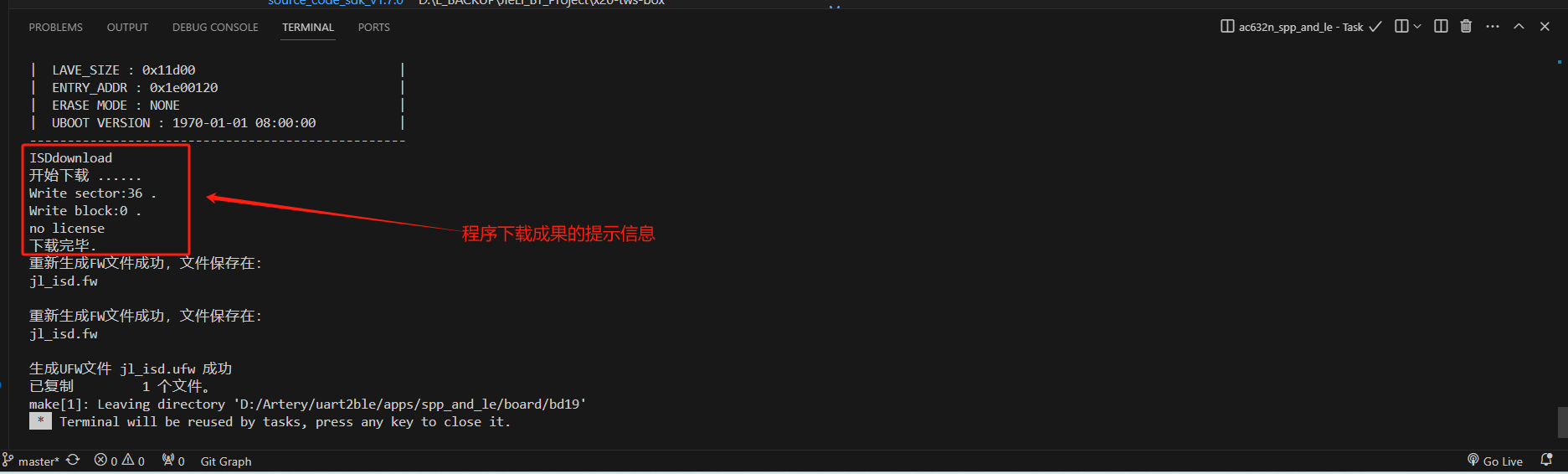
1. Connect the USB cable to the board as shown below. If the chip is blank, you don't need Jerry's forced upgrade development tool. Just prepare a USB data cable as shown in the image below. You won't need the data cable later when updating the program (because the source code of this project has OTA functionality enabled). You can update the software through Jerry's OTA upgrade mini-program (search "Jerry OTA"
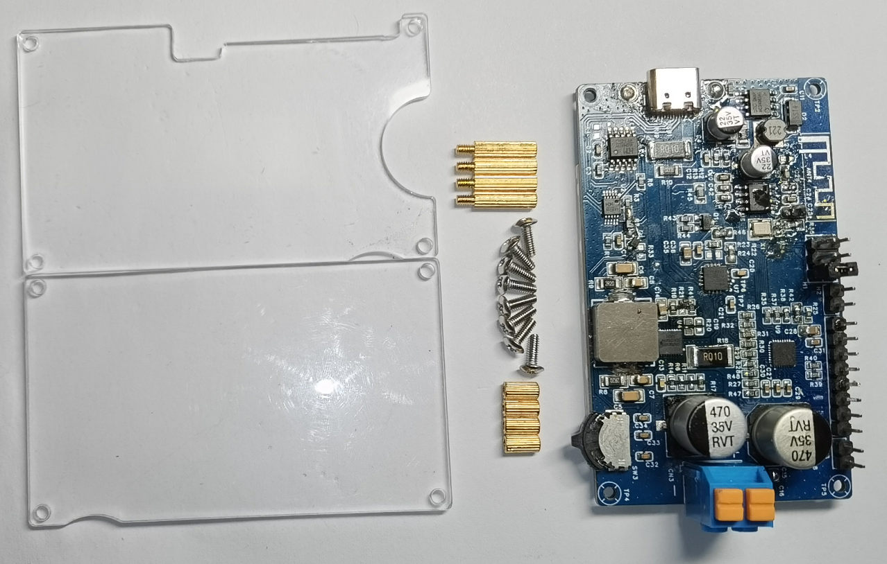
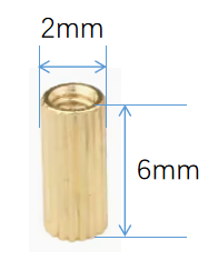
on WeChat ). After connecting the USB cable to the computer, you should see the following USB device in the computer's "Device Manager". 2. Open the SDK source code with VS Code, and compile and download the program as shown in the image below (if your VS Code doesn't have the Task Explorer plugin installed, you need to install it). You should eventually see the following prompt message, indicating that the program download is complete. 3. If OTA is required, the OTA file is in the following directory. Hardware Demonstration —————————————————————————————————————————————————————————————— 1. Copper Pillar Double-Pass: M2*6 4 pieces 2. Copper Pillar Single-Pass: M2*11+3 4 pieces 3. Screws: M2*6 8 pieces Current Known Issues in this Project! ——————————————————————————————————————————————————————————————————


1. The VBUS pin of the CH224K PD chip needs a 10kΩ resistor in series. The schematic has been updated, but the PCB layout remains unchanged.
2. The screen refresh rate is slow, with visible flickering.
3. A pull-down resistor needs to be added to the CE pin of the SC8721 in the voltage regulation circuit to ensure the chip is in the off state when powered on. The schematic has been updated, but the PCB layout remains unchanged.
4. The voltage/current adjustment method is not very convenient; I prefer using a knob. However, knobs take up space, making it difficult to make the device very small.
5. The output current detection circuit needs optimization. Currently, it detects output current when adjusting the voltage; the detection resistor needs to be moved outwards, after the feedback network and all filtering circuits.
6. The LCD pads are positioned slightly too high; they could be shifted downwards slightly.

If you found this project helpful, please give it a thumbs up.
Also, if you found this project useful, please feel free to bookmark it.
Other Attachments
————————————————————————————————————————————————————————————————
MCU source code address: https://gitee.com/Bryan_He/open_usb_power_supply.git
BLE source code address: https://gitee.com/Bryan_He/uart2ble.git
The current MCU firmware can be downloaded from the attachment below: usb-power-supply-MCU-Firmware.hex
The mini-program has been successfully launched. You can scan to open the mini-program (you can play with it to your heart's content):
Some users have reported that they cannot find the purchase channel for the MCU. The following is the link to the Yateli Tmall store:
Homepage - Yateli Flagship Store - Tmall.com
History
—————————————————————————————————————————————————————————————— Drafted on
2024-1-3
, outlining the requirements for this project;
1. 1. It can convert a USB power adapter into an adjustable DC power supply from 1.0V to 30V after conversion by a DC-DC adjustable buck-boost power supply chip.
2. It supports the PD3.0 protocol. When using a USB power adapter that supports PD3.0, it can communicate with the protocol to output voltages of 5V, 9V, 12V, 15V, and 20V.
2. Real-time detection and display of input voltage and current. 2.
Real-time detection and display of output voltage and current.
3. The output current can be set, and the output will be shut off if the set current is exceeded.
4. A user-friendly human-machine interface.
2024-1-5
Based on project requirements, a DC-DC buck-boost power supply chip and some other peripheral components were selected, and the preliminary hardware solution was selected:
1. DC-DC Buck-Boost: Southchip SC8721QFER, Vin: 2.7V to 22V; Vout: 2.7V to 22V
2. MCU: It is planned to use Arteri AT32F415KCU7
3. 4. Current detection: TI's INA3221AIRGVR is planned.
5. LCD: To be determined.
6. PD chip: CH224K, 4V to 22V input voltage, supports PD3.0/2.0, BC1.2 fast charging protocol.
(2024-01-10 :
Completed schematic and partial component layout)
(2024-01-24 17:50:39:
Completed all PCB routing, ordered PCB and SMT, organized materials, and applied for free PCB consumables)
(2024-01-31 19:39:
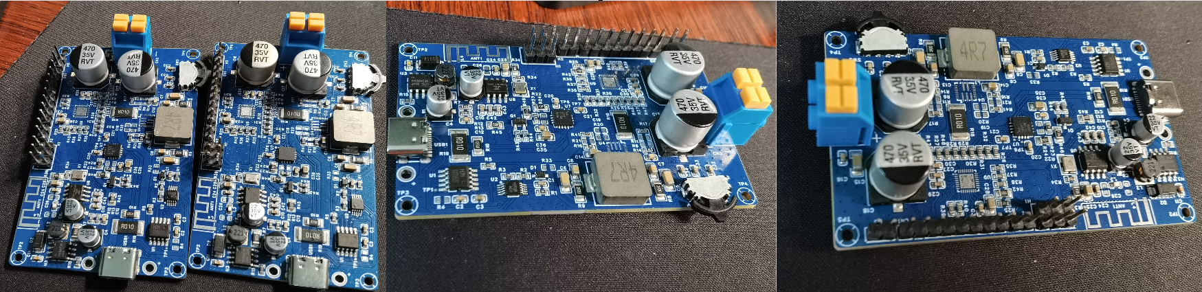
After waiting for several days, it finally arrived!! The board was SMT-mounted today and shipped to Shenzhen. I unpacked the package as soon as I got home. Below is a picture of the assembled board. Two boards were SMT-mounted free of charge. Finally, I don't have to do it by hand anymore,
it's so great!! Two chips were not available from LCSC, so I had to hand-solder them.)
February 1, 2024:
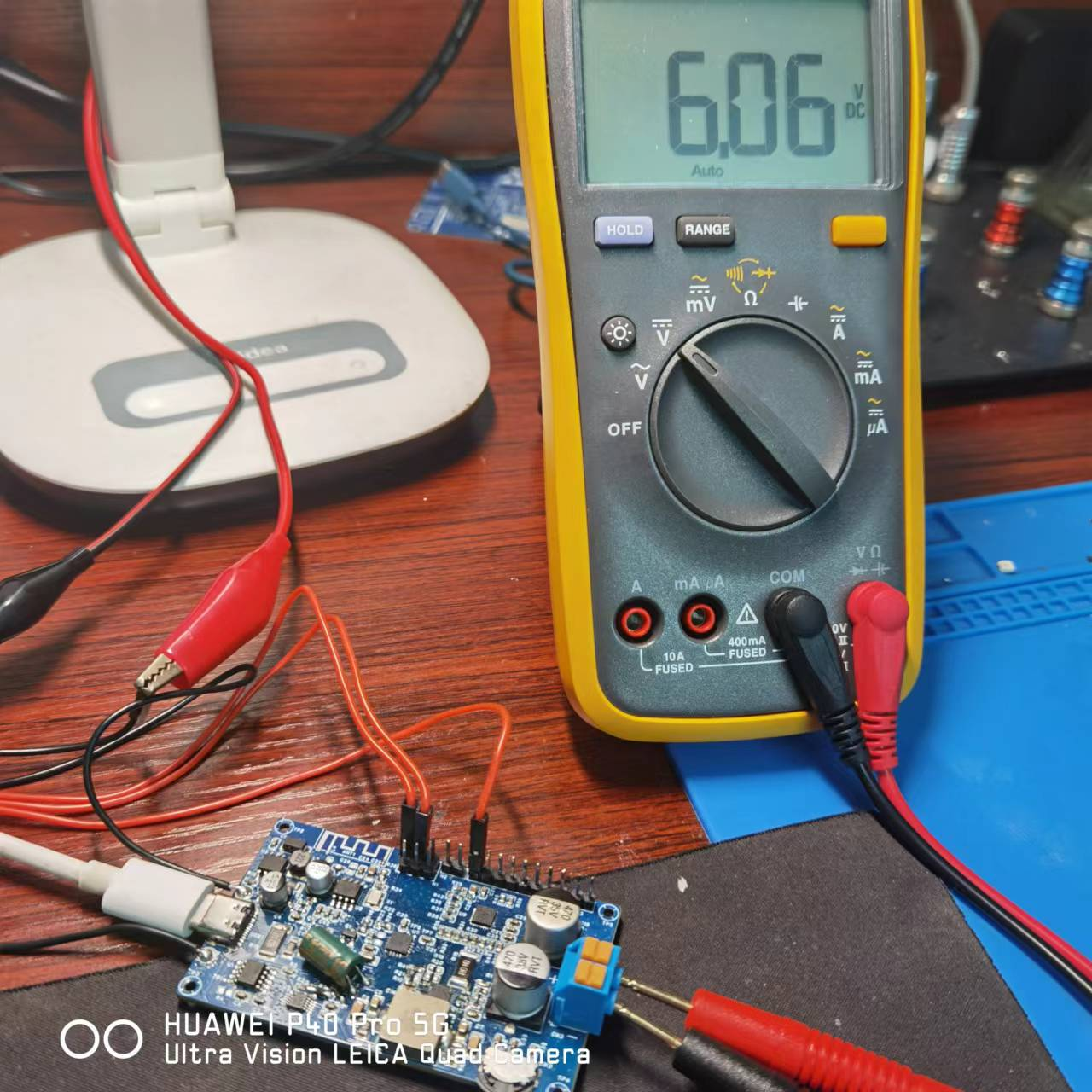
Today, I soldered on the missing components and prepared to power on the circuit to check the power supply. However, after powering on, I found that the 3.3V power supply to the MCU and other ICs was abnormal, only around 1.1V. Ugh, what a hassle!
After troubleshooting, I discovered that the resistor in the RC filter circuit of the power supply was incorrectly mounted.

February 2, 2024:
Completed the driver for the INT3221 and the detection of its input/output voltage/current. Started debugging the SC8721 driver. During debugging, I repeatedly controlled the CE pin, and unfortunately,
one board of SC8721s started smoking. It's inexplicable; I didn't apply any load. Why did this happen?
It seems I can only stop here before the New Year. I'm going back to my hometown tomorrow, and this problem can only be addressed after the New Year. I don't know if it's a hardware problem or a software control logic problem.
February 20, 2024:
SC8721 driver completed; output voltage can be adjusted in real time.
February 26, 2024, 11:38 PM:
Completed part of the LCD display and can refresh the monitored voltage and current in real time. Not bad!!
February 28, 2024, 11:48 PM :
Completed the entire layout display of part of the LCD!
March 1, 2024, evening :
Completed all LCD display and data detection refresh functions . March 2, 2024,
9:47 PM
: Wrote development documentation and organized open-source related files for project release .
March 10, 2024, 10:38 AM
: These past few days I've been debugging the Bluetooth part. Since I hadn't used this Bluetooth chip before, I encountered quite a few problems during debugging. Here's a record and sharing:
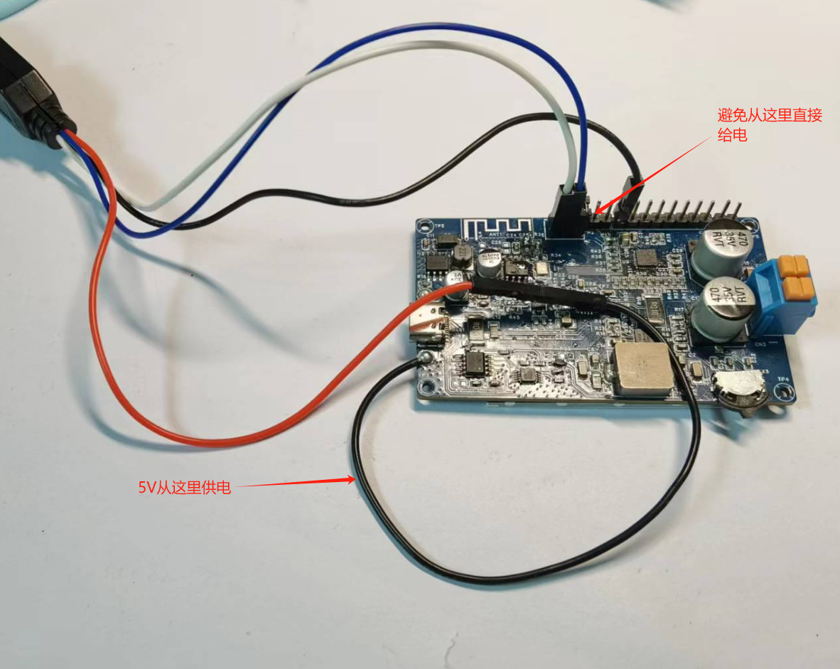
1. The chip's power supply cannot exceed 3.5V, otherwise the chip may be damaged. Why mention this? Because I damaged quite a few chips during debugging due to this power supply issue; this is mainly because Jerry's
download tool outputs 5V. We need to find a way to avoid this; during downloading, I powered the chip in this way to avoid burning it out.
2. When downloading the program for the first time, ensure that there is no external pull-down circuit on the PA9 port. If there is, disconnect it temporarily. This is because the chip has a default function of resetting the chip after a 4-second low-level signal on this port,
which will affect the program download.
3. The crystal oscillator's deviation cannot be too large. A large deviation will prevent Bluetooth from being detected. This problem troubled me for most of the debugging time because the program ran normally, but Bluetooth could not be found. After
further investigation, I found that the problem was with the crystal oscillator.
4. Here's a little tip to share: for most Jerry chips, if they're blank chips with no pre-installed programs, the first program download doesn't require any tools—just
a regular USB cable! Subsequent program updates can be done via OTA (provided the program is configured to enable BLE OTA). You
can find the mini-program by searching "Jerry OTA" on WeChat. OTA upgrades through this mini-program are very convenient, a great option for those who just want to experiment and don't want to spend money on tools (over 80 RMB)
.
March 10, 2024, 9:01 PM :
Received the acrylic board today and assembled a machine immediately. Thankfully, it went smoothly without any unexpected issues. Here's the result! Hmm... instantly upgraded!

March 17, 2024, Evening:
The WeChat mini-program's UI and basic Bluetooth communication functions are working.

March 23, 2024, Morning:
Completed all functions of the WeChat mini-program.
March 31, 2024 (Evening
): PCB component layout for version 2.0 began.

April 1 , 2024 (Evening
): The circuitry for version 2.0 was basically complete; one more round of optimization and layout is needed before release. April 6, 2024 (Evening) : The version 2.0 PCB was shipped for manufacturing; preparations are underway to procure some key materials. April 7, 2024: Many users applied to try out the mini-program, but only 15 members were available for the trial version. To repay everyone's support, I decided to launch the mini-program. Having no prior experience with mini-programs, I researched "How to Launch a Mini-Program" over the past few days and submitted the relevant filing materials today, awaiting review. Once approved, I will share the results with everyone as soon as possible. Thank you for your support! Version Iteration —— ... Hopefully, this project will help those who want to learn and tinker with embedded systems, providing a cost-effective and convenient solution for meeting device power supply needs during development and learning. Demo Video ————————————————————————————————————————————————————————————————

PMMA-TOP (Top Shell) - 1. STEP
PMMA-BTM (bottom shell) - 1. STEP
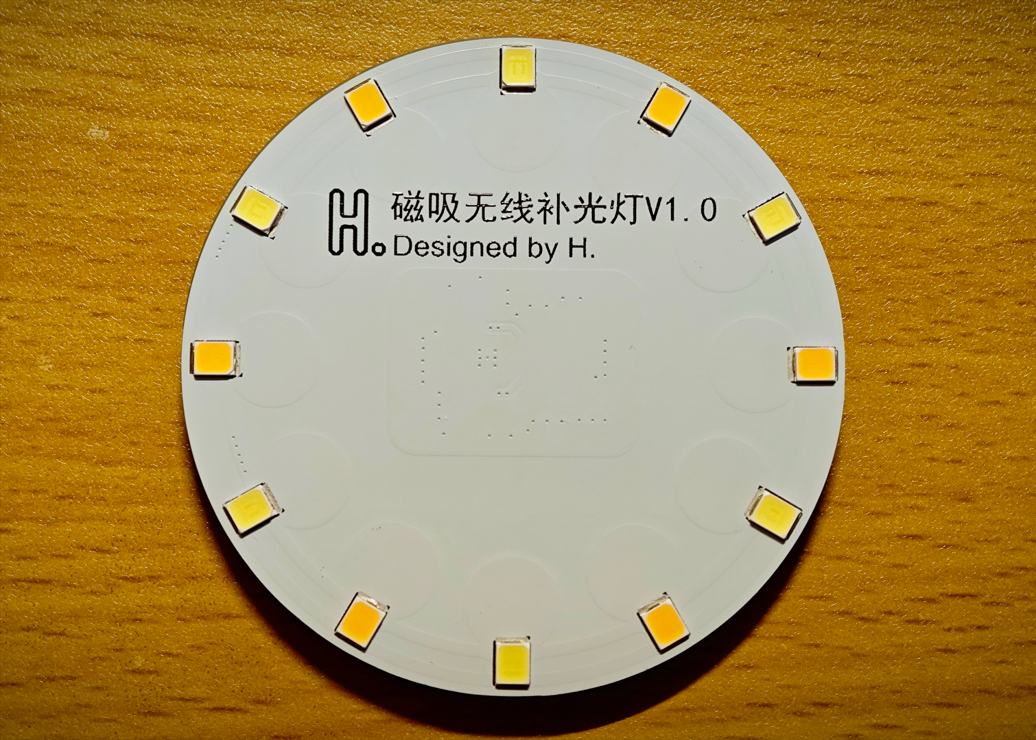
A magnetic fill light driven by the NU1680 wireless charging receiver module.
Bilibili video link: Click to play
Actual product image:

I. Function Introduction:
1. Supports Qi protocol.
2. Power 1.5W.
3. Wireless power supply, no need to charge, and no need to worry about running out of power.
4. A 3D-printed diffuser is designed; you can directly use the attached file and order through 3Dmonkey.
5. Approximately five times the brightness of a mobile phone flashlight.
II. Hardware Components:
1. The wireless receiver uses the NU1680, a highly integrated Qi receiver chip requiring only 12 external components.
2. The LED component consists of 12 2835 LEDs connected in parallel, with 6 warm-light and 6 cool-light LEDs, adjusted to a comfortable color temperature that can be changed according to personal preference.
3. The LEDs are directly connected to the power supply through current-limiting resistors, eliminating flicker, but there is no switch or dimming function; it lights up immediately upon power-on.
4. The total value of the current-limiting resistors (parallel algorithm) can be adjusted from 10Ω to 100Ω; the resistor shown in the Bilibili video is 10Ω.
III. Materials:
1. 0603 100NF*2 2. 0603 47NF*3 3. 0603 33NF*1 4. 0603 2.2NF*1 5. 0603 10UF*3 6. 0603 1UF*1
7. 0805 220Ω*1 8. 0805 220Ω*6 (current limiting resistors for LEDs, can be supplied separately, refer to point 4 of "Hardware").
9. 2835 LEDs*12 (color temperature can be supplied separately, refer to point 2 of "Hardware").
10. Coil: Diameter 25mm, thickness 1mm, inductance 15uH (datasheet requires 15.8uH but no corresponding value is available, so this is a substitute).
11. Magnetic shielding sheet: Diameter 50mm, thickness 0.3mm, soft magnetic sheet, single-sided adhesive backing.
12. Main control chip: NU1680.
13. C-type magnetic adhesive pads: Do not buy round ones, as they will affect the stability of wireless power transmission.
14. 3D lampshade material: LEDO 6060 SLA photosensitive resin.
IV. Replica Precautions:
1. Do not prototype boards with filenames ending in "_X"! They are stepping stones to success.
2. A total of four boards need to be prototyped: main board, component pads, coil bracket, and coil pad.
3. The coil pad was added after filming the video footage. After assembling according to the assembly structure in the video, simply add it to the coil side.
4. Pay special attention not to use "coil bracket" instead of "coil pad." Their inner diameters are different. The inner diameter of the coil pad is smaller, so it not only acts as a pad but also serves to hold the coil in place. 5.
Pay special attention to the thickness of the prototype. The required thickness of the board is indicated in the document layer of the PCB file.
6. Do not use the BOM table provided by this open source; it is automatically generated and has not been carefully modified. Component parameters and reference numbers should be defined according to the schematic diagram.
7. The open-source documentation may not be very detailed; it just covers everything I can think of. If you have any questions, please leave a comment.
Thank you for watching!
Have a nice day and a successful remake!
57mm curved lampshade.
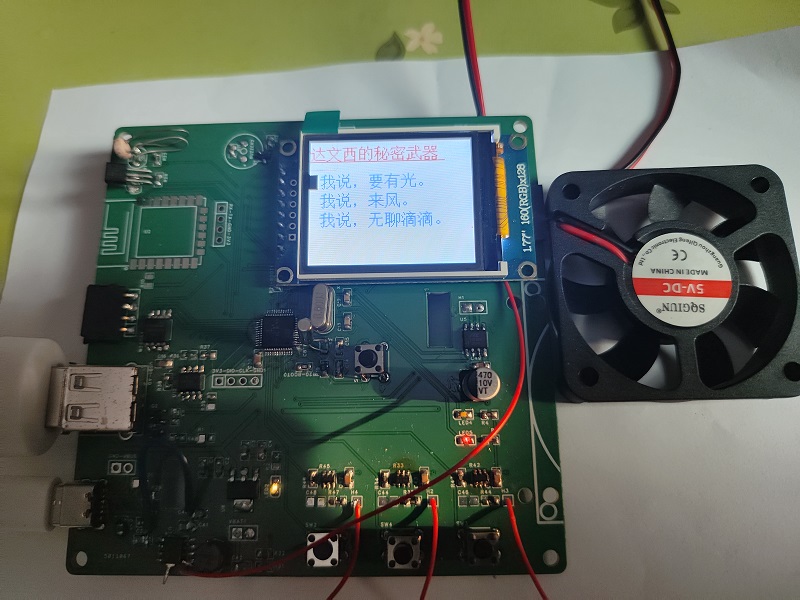
It can be a flashlight—it lights up when there's light. No light? Absolutely nothing!
When it's hot, it can be a small fan, perfect for drying your hair.
When you're bored, you can read a novel.
In case of danger, it can be used as a safety shield.
The flashlight function is controlled by a photoresistor that detects light intensity. It
uses an IP5305 rechargeable lithium battery, allowing you to use it outdoors.
The fan uses an RZ7888 motor control chip.
Novels and documents are downloaded using an ESP8266EX/ESP12F and saved to the W25Q flash memory.
With a large 1.8-inch screen, you won't have trouble seeing the text clearly.
VID_20240418_171906.mp4_20240419_101948.mp4_20240420_124441.mp4
VID_20240418_171933.mp4_20240419_102052.mp4_20240420_124526.mp4
PDF_Da Vinci's Secret Weapon.zip
Altium_Da Vinci's Secret Weapon.zip
PADS_Da Vinci's Secret Weapon.zip
BOM_Da Vinci's Secret Weapon.xlsx
95137
Guangdong Baiyun College Business Card
Guangdong Baiyun College
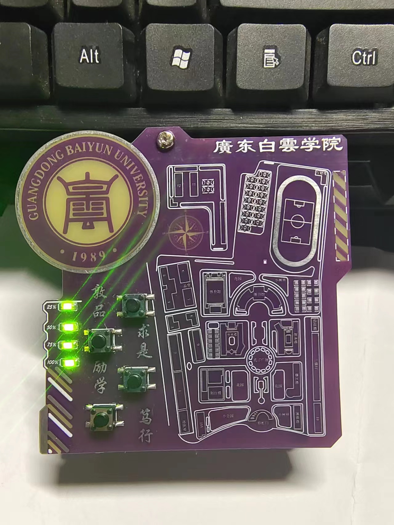
Connecting the LEDs and button pads on the upper and lower boards with wires
allows soldering of a 3.7V battery.
The TYPE-C rechargeable
LED power indicator
section can be referenced from the author sam_god's open-source project. [Map of Guangdong Baiyun University (West Campus) - JLCPCB EDA Open Source Hardware Platform (oshwhub.com)].
If there is any copyright infringement, please contact us for removal.
0.hex
BOM_af3f0377304546c0b5a75c6452de7cc3_20231206170404.xls
PDF_Guangdong Baiyun University Business Card.zip
Altium_Guangdong Baiyun College Business Card.zip
PADS_Guangdong Baiyun College Business Card.zip
BOM_Guangdong Baiyun University Business Card.xlsx
95139
YBA-AMS_Remix
3D Printing Single-Channel Material Holder Control Board
Modified from YBA-AMS
.
⚠ Please note that although the current version can be supplied with the AMS lite connector, its power consumption is quite high. Please consider this carefully. The next version of the PCB will be compatible with MP1584 to solve the LDO power consumption issue. You can wait for this to be resolved before manufacturing.
Recommended process
:
Board thickness: 1.6mm
Minimum hole diameter/outer diameter: 0.3mm (free) (outer diameter 0.4/0.45)
Add markings to the board: Add serial number QR code
QR code size: 8*8mm
QR code location: Designated location
Modified content:
Changed 4 channels to 1 channel for convenient individual control in the consumable drying box.
Changed USBC/DC power supply to AMS lite interface power supply.
DRV8833 was modified from a finished board for soldering, optimizing the PCB area.
The manual control switch has been changed from wiring to soldering, directly fixing it to the consumable drying box.
You can see both the switch board and motor board in this project; this is designed to optimize wiring within the drying box. It requires the next version of the spool holder. You can check the update status of [YBA-AMS(Remix)] on MakerWorld.
Modified note:
From 4 channels to 1 channel, to control the sole holder in one case.
From USB-C/DC power supply to AMS lite.
From finished DRV8833 board to soldered DRV8833.
From cable-connected switch to soldered switch on board.
You can find the switch board and motor board in this project; it's designed for the cable management in case. They should be used with the next version of the spool holder; you can kindly check the update status of [YBA-AMS(Remix)] on MakerWorld.
BOM_PCB[YBA-AMS(Remix)].xlsx
PDF_YBA-AMS_Remix.zip
Altium_YBA-AMS_Remix.zip
PADS_YBA-AMS_Remix.zip
BOM_YBA-AMS_Remix.xlsx
95140
AT8236 Motor Driver Board & Power Board
This driver module uses the AT8239 motor driver and a TPS5450DDA to provide a 5V 5A power output.
This project serves as the power driver module for a ROS car. All interfaces are connected to the control core board using simple horn-shaped connectors and FC cables, simplifying the board and reducing costs. Any board issues are addressed by simply replacing the faulty one. The board

also uses two TPS5450DDA converters for 5V/5A output to power the host computer, Raspberry Pi, or other modules like Luban Cat. Theoretically, the maximum output is 5A, but this hasn't been tested due to the lack of a load tester. However, both output voltages are quite good. Solid-state capacitors are used throughout the board. An INA219 was added for circuit detection, which provides more data compared to an ADC, such as current, voltage, and power.
The 3.3V connection was initially forgotten, so a jumper wire was used; this has now been fixed in the project, and you can confidently build a board if needed.
The TPS5450DDA circuit can also be extracted from the schematic and used. It has been tested and works without issue. It also provides a 3.3V output from the ASM1117 without any problems.
The board also has an onboard buzzer and two controllable 5V outputs, which can be controlled via GPIO for future expansion. I plan to add a USB hub later, using this 5V interface to power peripherals, since the ROS car will also have a depth camera and LiDAR.
The most important part of the motor driver board is the motor drive. One path has been tested and works without any issues. I'm unsure how to upload the video, so please feel free to discuss it. I'm not a professional, and the board certainly has many problems, so please bear with me.
087953d0fc2162f3f086e0ffda9efc82.mp4
369ebe43be84a53d48402c6f511059b2.mp4
PDF_AT8236 Motor Driver Board & Power Board.zip
Altium_AT8236 Motor Driver Board & Power Board.zip
PADS_AT8236 Motor Driver Board & Power Board.zip
BOM_AT8236 Motor Driver Board & Power Board.xlsx
95141
Liangshan School Electronic Keyboard Expansion Board
Liangshan School Electronic Keyboard Expansion Board
Design of Electronic Keyboard Expansion Board Based on LCSC Liangshanpai:
1. Objective: To become familiar with the development process of embedded projects and master the ability to design a game console hardware circuit, software programming, and system debugging.
2. Function Introduction:
Implements I2C display of current information; (to be implemented later, already driven. Unsure of its use yet)
Implements 23-button control;
includes sound output functionality;
3. Skills Acquired:
Hardware Development Ability
: Learns embedded project circuit analysis skills and how to understand schematic diagrams;
gains basic skills in component selection and datasheet reading;
learns schematic and PCB design skills, cultivating independent project design thinking;
understands the design of I2C screens, PWM audio circuits, etc.;
masters the use of instruments such as multimeters, oscilloscopes, signal generators, and student power supplies, possessing basic circuit analysis skills;
masters the use of tools such as soldering irons and hot air guns, possessing component soldering and hardware debugging skills, becoming a new generation of "soldering masters";
Software Development Ability:
Understands the basic functions and peripherals of GD32, and gets started with GD32 project development;
understands audio encoding formats and implements audio output;
understands the I2C protocol and OLED driver principles, and implements screen driving;
masters interface creation;
understands the basic working principles of audio;
masters embedded software development, code reading, and bug debugging methods and techniques;
GD32F450.hex
Electronic Keyboard.rar
501da5fe7d2ef95f369b09376aec2983.mp4
PDF_Liangshan School Electronic Keyboard Expansion Board.zip
Altium_Liangshanpai Electronic Keyboard Expansion Board.zip
PADS_Liangshanpai Electronic Keyboard Expansion Board.zip
BOM_Liangshanpai Electronic Keyboard Expansion Board.xlsx
95143
electronic


 京公网安备 11010802033920号

 177-714-5-21CS4J1-24RAN


