Bilibili video link: Click to play
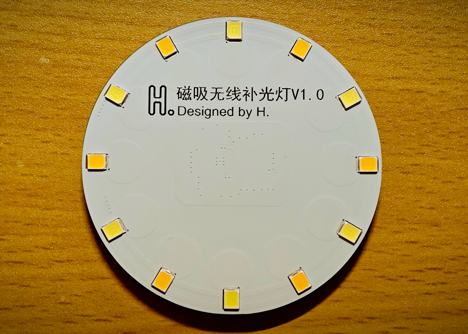
Actual product image:

I. Function Introduction:
1. Supports Qi protocol.
2. Power 1.5W.
3. Wireless power supply, no need to charge, and no need to worry about running out of power.
4. A 3D-printed diffuser is designed; you can directly use the attached file and order through 3Dmonkey.
5. Approximately five times the brightness of a mobile phone flashlight.
II. Hardware Components:
1. The wireless receiver uses the NU1680, a highly integrated Qi receiver chip requiring only 12 external components.
2. The LED component consists of 12 2835 LEDs connected in parallel, with 6 warm-light and 6 cool-light LEDs, adjusted to a comfortable color temperature that can be changed according to personal preference.
3. The LEDs are directly connected to the power supply through current-limiting resistors, eliminating flicker, but there is no switch or dimming function; it lights up immediately upon power-on.
4. The total value of the current-limiting resistors (parallel algorithm) can be adjusted from 10Ω to 100Ω; the resistor shown in the Bilibili video is 10Ω.
III. Materials:
1. 0603 100NF*2 2. 0603 47NF*3 3. 0603 33NF*1 4. 0603 2.2NF*1 5. 0603 10UF*3 6. 0603 1UF*1
7. 0805 220Ω*1 8. 0805 220Ω*6 (current limiting resistors for LEDs, can be supplied separately, refer to point 4 of "Hardware").
9. 2835 LEDs*12 (color temperature can be supplied separately, refer to point 2 of "Hardware").
10. Coil: Diameter 25mm, thickness 1mm, inductance 15uH (datasheet requires 15.8uH but no corresponding value is available, so this is a substitute).
11. Magnetic shielding sheet: Diameter 50mm, thickness 0.3mm, soft magnetic sheet, single-sided adhesive backing.
12. Main control chip: NU1680.
13. C-type magnetic adhesive pads: Do not buy round ones, as they will affect the stability of wireless power transmission.
14. 3D lampshade material: LEDO 6060 SLA photosensitive resin.
IV. Replica Precautions:
1. Do not prototype boards with filenames ending in "_X"! They are stepping stones to success.
2. A total of four boards need to be prototyped: main board, component pads, coil bracket, and coil pad.
3. The coil pad was added after filming the video footage. After assembling according to the assembly structure in the video, simply add it to the coil side.
4. Pay special attention not to use "coil bracket" instead of "coil pad." Their inner diameters are different. The inner diameter of the coil pad is smaller, so it not only acts as a pad but also serves to hold the coil in place. 5.
Pay special attention to the thickness of the prototype. The required thickness of the board is indicated in the document layer of the PCB file.
6. Do not use the BOM table provided by this open source; it is automatically generated and has not been carefully modified. Component parameters and reference numbers should be defined according to the schematic diagram.
7. The open-source documentation may not be very detailed; it just covers everything I can think of. If you have any questions, please leave a comment.
Thank you for watching!
Have a nice day and a successful remake!


 京公网安备 11010802033920号

 2675-1001-30


