Design of a portable and simple oscilloscope based on GD32E230C8T6.
A digital oscilloscope is an instrument used to display electrical signal waveforms. It mainly consists of analog front-end processing circuit, microcontroller circuit, power supply circuit, control circuit, trigger circuit, calibration circuit, etc.
Since this project is an introductory project for oscilloscopes, some core circuits were selected in the circuit design to help beginners better understand the principles and design methods of oscilloscopes. The main circuits include the following:
(1) Analog front-end processing circuit: responsible for processing the input detection analog signal and then sending it to the microcontroller for recognition. The specific circuits include AC/DC coupling selection circuit, voltage attenuation circuit, signal processing circuit, and frequency detection circuit, which is the core of the entire circuit.
(2) Power supply circuit: responsible for providing positive and negative power to the operational amplifier and system power supply, which is the basis for ensuring the normal operation of the circuit.
(3) Microcontroller circuit: provides the control core for the system and is responsible for the acquisition, processing, and output of input signals.
(4) Human-computer interaction circuit: used to control the functions of the oscilloscope, including buttons, knobs, LEDs, display screen, and other input/output interfaces, providing a foundation for the development of oscilloscope functions.
Measurement range: -80V — +250V
Data Learning and Downloads
GD32E230 Data: https://lceda001.feishu.cn/wiki/Tlp5wNmPii2oKekezjpcCeA7ndh
Open Source Oscilloscope Data: https://www.yuque.com/wldz/jlceda/dso
Program Data Download: https://gitee.com/chen11232/GD32E230-Oscilloscope
Bilibili Video Link: https://www.bilibili.com/video/BV1Ct421G7qi/?share_source=copy_web&vd_source=7d6b44d04710561a688ec20e7b994b95
Oscilloscope Materials and Preparation
1. Purchase the PCB according to the BOM or schematic diagram; other parts are described below.
2. The overall components include: PCB board + 1.8-inch screen + lithium battery + oscilloscope probe.
3. Oscilloscope Probe: Uses an SMB interface. This circuit is compatible with SMA interfaces; it can be replaced with an SMA interface if needed.
4. Lithium Battery: Uses a 3x3x0.9cm (1000mAh) battery, or a battery of the same size but with a larger capacity.
5. Screen: Uses a 1.8-inch TFT color screen with an ST7735 driver chip.
6. Housing: 3D printed plastic material (resin may be too hard to install).
7. Terminals: M3*9.5mm screw posts, M3*8 screws (used for 3D printed housing).
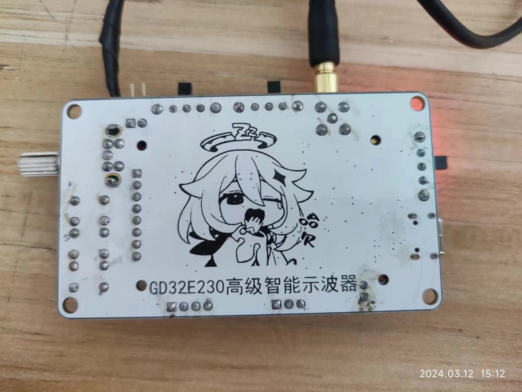
Top and

Bottom Physical Samples:
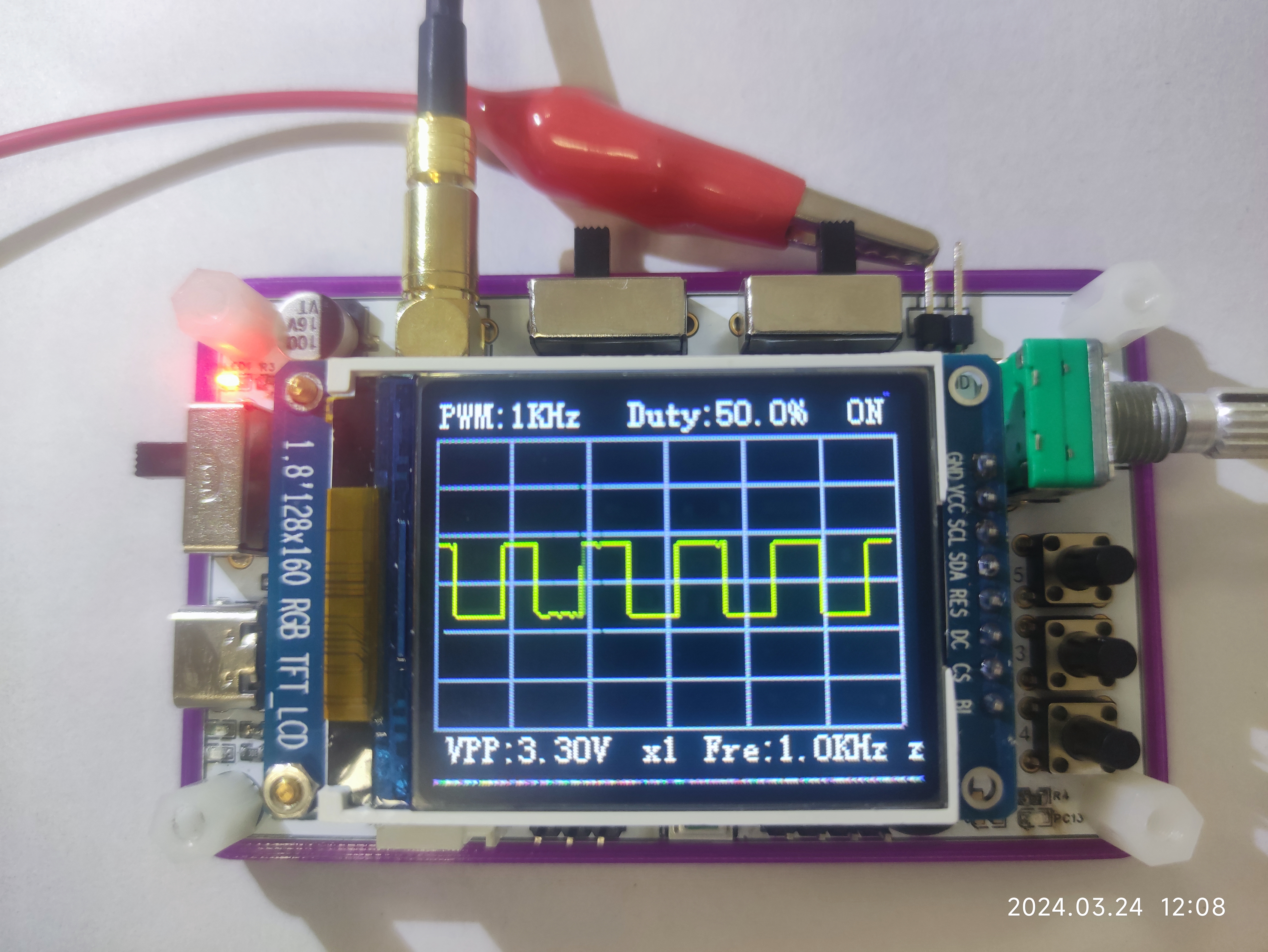
Waveform Input/Output Display:
Tested using an oscilloscope probe to measure the oscilloscope's built-in PWM output waveform.
Code Optimization:

3D Housing Modeling Effect:
Modeled using LCSC EDA Professional Edition + SolidWorks. The specific model file can be found in the project download section.


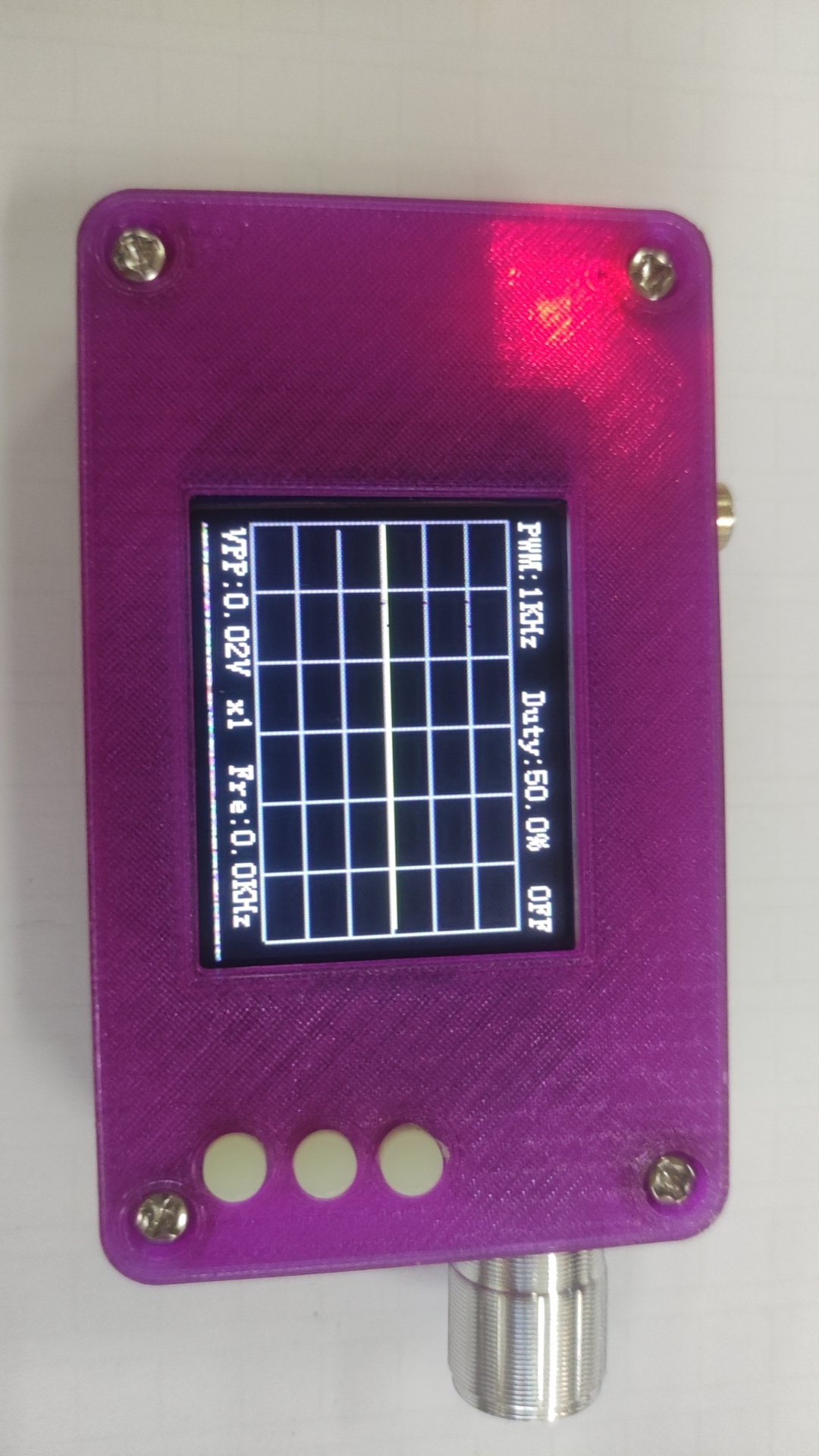
3D Housing Physical Sample Display
: The physical sample is printed. I originally wanted a more flashy color, but the effect is surprisingly poor. If you want to replicate it, you can consider changing to other colors. The size of this housing is fine.


 京公网安备 11010802033920号

 LBS140A11_10


