I recently built a T113-S3 gateway in my spare time. Initially, it was a complete board solution, but I found that modifying the peripherals and re-fabricating the board was too troublesome, so I changed it to a core board plus a baseboard solution. I'm now open-sourcing the core board, which integrates an RTL8201 100Mbps Ethernet and an XR829 Bluetooth/Wi-Fi, onboard eMMC, and reserved SDNAND pads. Except for the I/O occupied by the aforementioned components, all other I/O is brought out. The board can boot into the system via eMMC, and the USB network card can ping. The 100Mbps Ethernet PHY and XR829 haven't been tested yet, but they shouldn't be a problem in principle. It was taken from my previous complete board solution. If there are no problems after further testing, I will update the BuildRoot source code.
Just a quick rant: I spent all night installing the eMMC balls, and my eyes are practically blind! Everyone should just use SDNAND...
A simple oscilloscope based on GD32, compatible with STM32 and CW32 microcontrollers.
Two versions of the simplified digital oscilloscope
were developed: a development version and a bare-chip version.
The design largely references the official documentation – "Simple Digital Oscilloscope Project Documentation (yuque.com)" –
including pinout diagrams and charging
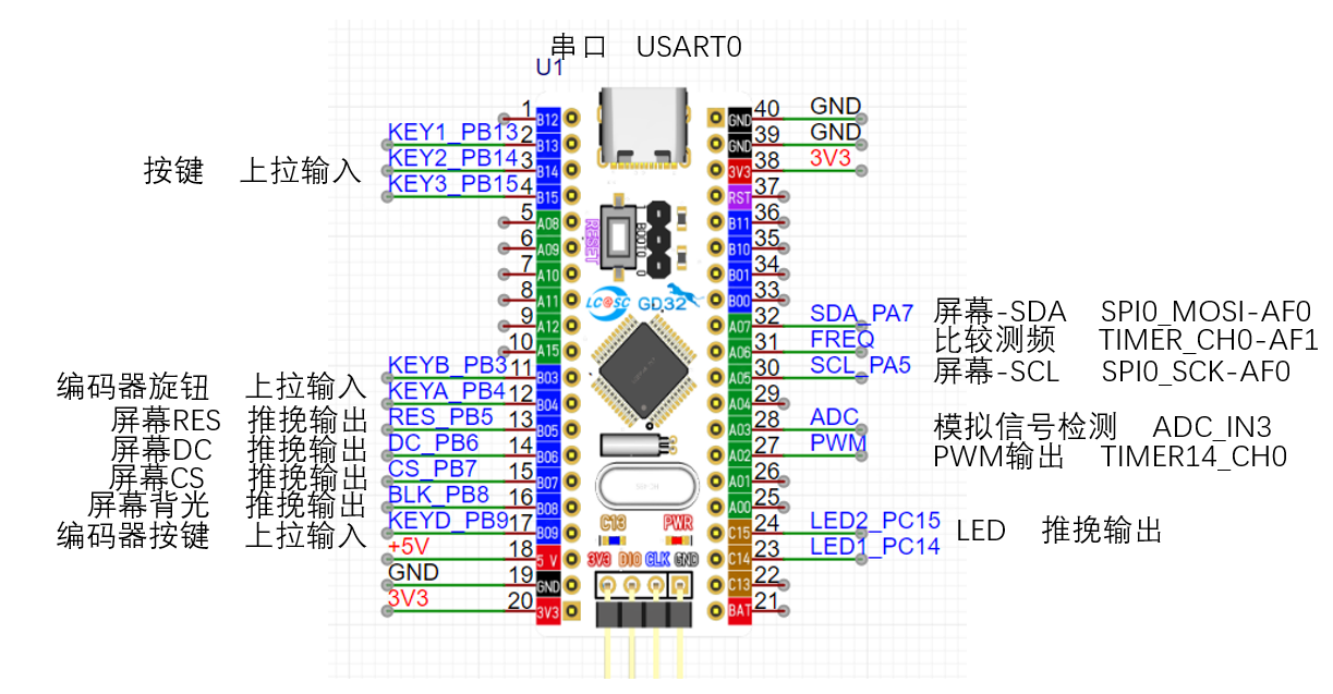
circuit design.
The charging chip uses the IP5306 power bank charging and discharging management chip, with 2.1A charging and 2.4A discharging, which is considered fast charging for the oscilloscope's small battery. The chip features output overcurrent, overvoltage, and short-circuit protection; input overvoltage, overcharge, over-discharge, and overcurrent discharge protection; and overall over-temperature protection. It supports simultaneous charging and discharging, one-button power on/off, and an LED power display.
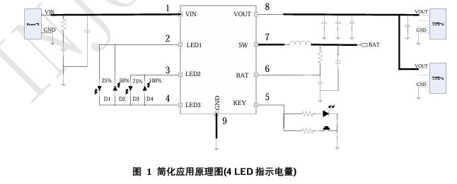
The image above is the reference circuit design schematic from the official datasheet. Too many LED power indicators on the circuit board would be visually unappealing, so one indicator light is reserved for charging and discharging indication. A power detection circuit is designed to display the current power level on the screen. The
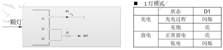
design references the single-LED reference circuit in the datasheet. Power detection uses two resistors to divide the battery voltage, and the microcontroller's ADC pin detects the voltage magnitude.
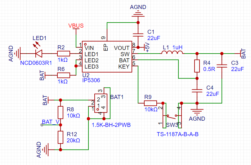
Voltage divider calculation formula: UBAT_v = R12 / (R8 + R12) * UBAT
power supply circuit design,

screen driver circuit design,
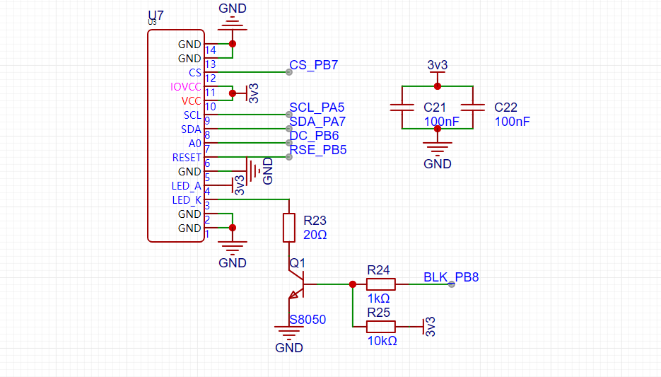
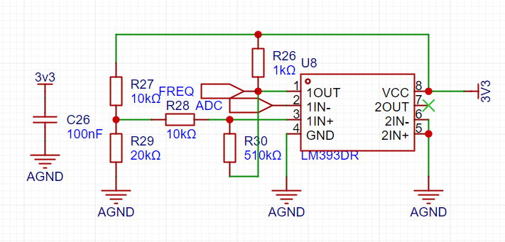
analog front-end circuit design,

comparison frequency measurement circuit,
chip core and peripheral circuit design,
core circuit

, peripheral circuit

, other circuit design
, button circuit

, LED indicator circuit,

encoder circuit

code modification. Modify
the screen orientation
by modifying the macro definition in Hardware/tft_init.h:
#define USE_HORIZONTAL 2 // Set landscape or portrait display 0 or 1 for portrait, 2 or 3 for landscape.
Modify the screen pixel offset
by modifying the function TFT_Address_Set in Hardware/tft_init.c to offset x1, x2, y1, y2 by addition and subtraction.
TFT_WR_REG(0x2a); // Column address setting TFT_WR_DATA(x1+1); TFT_WR_DATA(x2+1); TFT_WR_REG(0x2b); // Row address setting TFT_WR_DATA(y1+2); TFT_WR_DATA(y2+2); TFT_WR_REG(0x2c); // Write to memory. The waveform display area in
the full-screen waveform
source code is too small, making it difficult to observe waveforms with lower frequencies. Therefore,
the function drawCurve in Hardware/tft.c is modified to make the display width less than 160.
/*
* Function content: Draw a polyline
* Function parameters: short int rawValue -- Y-axis parameter value
* Return value: None
*/
void drawCurve(uint8_t yOffset,short int rawValue)
{
uint16_t x=0,y=0,i=0;
if((rawValue >= 40)||(rawValue
rawValue=40;
}
y = yOffset - rawValue; //data processing code
if(firstPoint)//If this is the first time drawing a point, no connection is needed, just plot the point
{
TFT_DrawPoint(0,y,CurveColour);
lastX=0;
lastY=y;
firstPoint=0;
}
else
{
x=lastX+1;
if(x
{
TFT_DrawLine(lastX,lastY,x,y,CurveColour);
for(i=0;i
{
TFT_DrawPoint(x+1,i,BLACK);//Draw the point
}
lastX=x;
lastY=y;
}
else // If the screen width is exceeded, clear the screen and start drawing from the first point to achieve a dynamic update effect
{
TFT_DrawPoint(0,y,CurveColour);
lastX=0;
lastY=y;
}
}
}
Modify the display UI
. After modifying the waveform display area, the original display UI will be disordered, so modify it
in Hardware/tft.c. Modify the static UI display function TFT_StaticUI and the display parameter function TFT_ShowUI to
/** Function content: Static UI * Function parameters: None * Return value: None */ void TFT_StaticUI(void){ uint16_t i=0,j=0; char showData[32]={0}; //TFT_ShowChinese(10,0,(uint8_t *)"Simple Oscilloscope",BLACK,GREEN,16,0); sprintf(showData," PWM "); TFT_ShowString(5,72,(uint8_t *)showData,BLACK,YELLOW,16,0); memset(showData,0,32); TFT_ShowChinese(55,56,(uint8_t *)"Output Status",WHITE,PURPLE,12,0); sprintf(showData," "); TFT_ShowString(55,72,(uint8_t *)showData,BLACK,YELLOW,16,0); memset(showData,0,32); TFT_ShowChinese(110,56,(uint8_t *)"Output frequency",WHITE,PURPLE,12,0); sprintf(showData," "); TFT_ShowString(110,72,(uint8_t *)showData,BLACK,YELLOW,16,0); memset(showData,0,32); sprintf(showData," "); TFT_ShowString(110,92,(uint8_t *)showData,WHITE,PURPLE,12,0); memset(showData,0,32); TFT_ShowChinese(118,92,(uint8_t *)"Duty Cycle",WHITE,PURPLE,12,0); sprintf(showData," "); TFT_ShowString(110,106,(uint8_t *)showData,BLACK,YELLOW,16,0); memset(showData,0,32); TFT_ShowChinese(5,92,(uint8_t *)"Input amplitude",WHITE,PURPLE,12,0); TFT_ShowChinese(55,92,(uint8_t *)"Input frequency",WHITE,PURPLE,12,0); for(i=0;i { TFT_DrawPoint(106,i,YELLOW); } for(i=0;i { TFT_DrawPoint(i,51,BorderColour); } for(i=0;i { TFT_DrawPoint(0,i,BorderColour); } for(i=0;i { TFT_DrawPoint((i*10)+2,52,BorderColour); TFT_DrawPoint((i*10)+3,52,BorderColour); } for(i=0;i { TFT_DrawPoint((i*10)+2,53,BorderColour); TFT_DrawPoint((i*10)+3,53,BorderColour); }}/** Function content: Display string * Function parameters: uint16_t vpp--peak-peak value * uint16_t freq-frequency * float DoBias--DC bias signal * Return value: None */void TFT_ShowUI(volatile const struct Oscilloscope *value){ char showData[32]={0}; sprintf(showData,"%1.2fV ",(*value).vpp); TFT_ShowString(5,106,(uint8_t *)showData,BLACK,GREEN,16,0); memset(showData,0,32); if((*value).gatherFreq>=1000) { sprintf(showData,"%2.0fKHz",(*value).gatherFreq/1000.0f); TFT_ShowString(55,106,(uint8_t *)showData,BLACK,GREEN,16,0); memset(showData,0,32); } else { sprintf(showData,"%3.0fHz ",(*value).gatherFreq); TFT_ShowString(55,106,(uint8_t *)showData,BLACK,GREEN,16,0); memset(showData,0,32); }
if((*value).ouptputbit == 1) { TFT_ShowChinese(55,72,(uint8_t *)"Open",BLACK,YELLOW,16,0); } else { TFT_ShowChinese(55,72,(uint8_t *)"Close",BLACK,YELLOW,16,0); } if((*value).outputFreq>=1000) { sprintf(showData,"%3dKHz",(*value).outputFreq/1000); TFT_ShowString(110,72,(uint8_t *)showData,BLACK,YELLOW,16,0); memset(showData,0,32); } else { sprintf(showData," %3dHz",(*value). outputFreq); TFT_ShowString(110,72,(uint8_t *)showData,BLACK,YELLOW,16,0); memset(showData,0,32); }
sprintf(showData,"%3.1f%% ",(((*value).pwmOut)/((*value).timerPeriod+0.0f))*100); TFT_ShowString(110,106,(uint8_t *)showData,BLACK,YELLOW,16,0); memset(showData,0,32); }
Add pwm to enable indicator light
= Add the header file for the LED indicator light in Hardware/key.c, and modify
case KEY2 in the key handling function Key_Handle: if((*value).ouptputbit == 0) { (*value).ouptputbit=1; timer_enable(TIMER14); Open_LED(1); } else { (*value).ouptputbit=0; timer_disable(TIMER14); CLose_LED(1); } break;
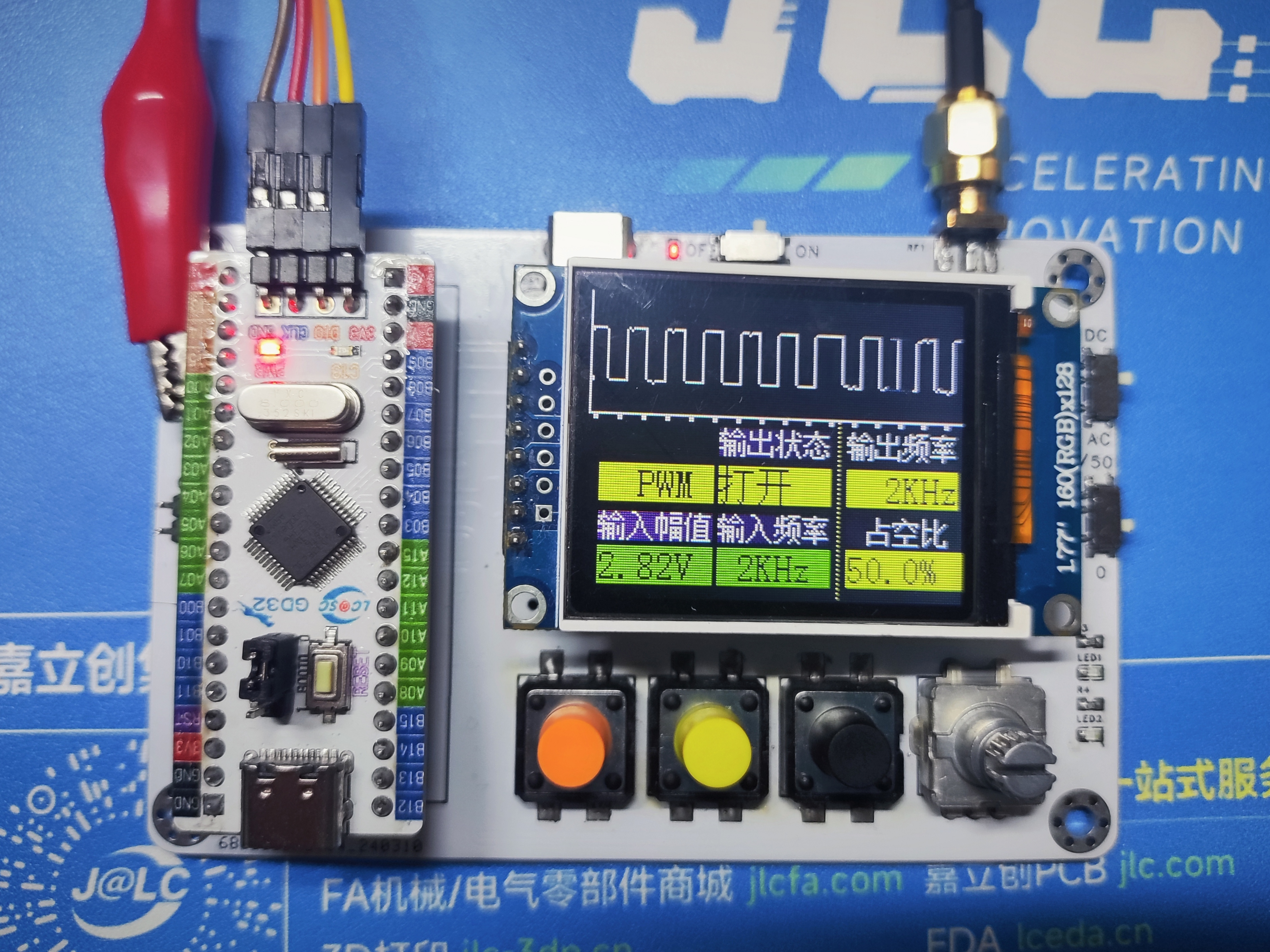
Finished product display


Oscilloscope Housing.zip
Oscilloscope.zip
PDF_#Training Camp#Digital Oscilloscope.zip
Altium_#Training Camp#Digital Oscilloscope.zip
PADS_#Training Camp#Digital Oscilloscope.zip
BOM_#Training Camp#Digital Oscilloscope.xlsx
95378
Commemorative Commemoration of the 23rd Enrollment Class of Lüliang Vocational and Technical College
Commemorative Commemoration of the 23rd Enrollment Class of Lüliang Vocational and Technical College
This version does not include a schematic diagram. (It will be added later when time permits.)
The text and images on the PCB can be modified according to your needs (as long as they are legal).
Because this was uploaded temporarily, it has not been verified.
Please order and modify with caution!
PDF_Lvliang Vocational and Technical College 23rd Enrollment Commemorative Edition.zip
Altium_Lvliang Vocational and Technical College 23rd Enrollment Commemorative Edition.zip
PADS_Lvliang Vocational and Technical College 23rd Enrollment Commemorative Edition.zip
BOM_Lvliang Vocational and Technical College 23rd Enrollment Commemorative File.xlsx
95379
electronic
 Just a quick rant: I spent all night installing the eMMC balls, and my eyes are practically blind! Everyone should just use SDNAND...
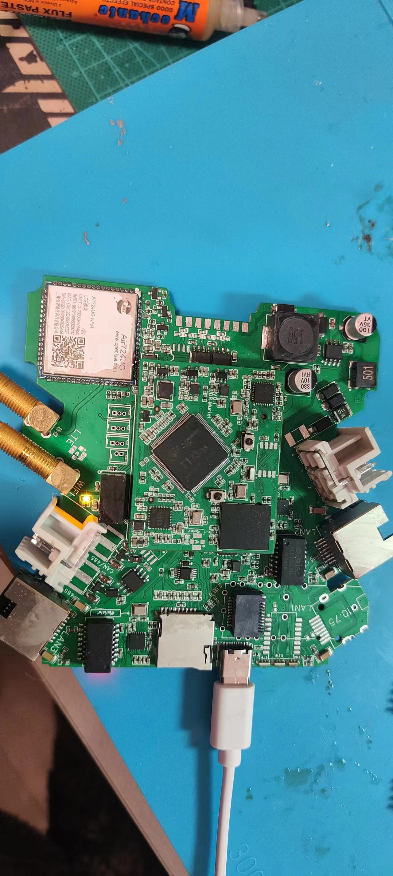


 京公网安备 11010802033920号

 CR102433FE


