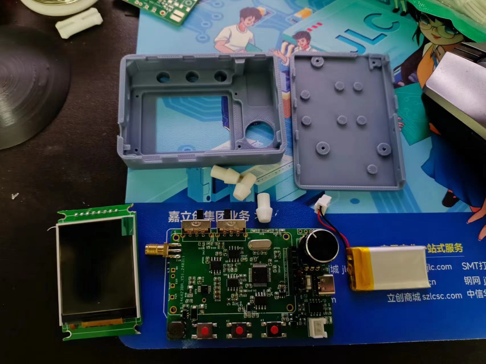
A simple oscilloscope designed based on the GD32 microcontroller , with a one-button power-on/off circuit added
following the official example . Press and hold for 3 seconds to power off. However, some components I used (such as buttons, switches, and the screen) are inconsistent with the BOM and model exported by JLCPCB. My 3D casing model is based on my physical prototype, requiring modifications to the casing for others to use . For easier wiring, I changed the screen pinouts, resulting in incompatibility between the program and the official design.

GD32 oscilloscope housing. Step
202403271925.mp4
PDF_#Training Camp#GD32 Oscilloscope.zip
Altium_#Training Camp#GD32 Oscilloscope.zip
PADS_#Training Camp#GD32 Oscilloscope.zip
BOM_#Training Camp#GD32 Oscilloscope.xlsx
95436
Bluetooth Portable Decoding Headphone Amplifier
Bluetooth portable DAC/amplifier, architecture based on QCC3034 + PCM5102A + LM4881, gum-sized, HiFi.
The main features of this
Bluetooth portable decoding headphone amplifier,
compared to other QCC projects from LCSC, are:
1. Battery charging and discharging design;
2. Compact size, only 18*70mm;
3. Headphone amplifier output, although not high power, is sufficient for IEMs and earbuds.
Additionally: I personally don't have much expertise in sound tuning and can't hear many subtle differences; I can only say that I think it sounds good. If you have specific requirements, I suggest making minor design adjustments.
Architecture:
1. The QCC3034 module serves as either Bluetooth to I2S output or USB to I2S output. USB supports 48kHz*16bit, and Bluetooth supports protocols such as aptX/aptX-HD/ANC/LDAC depending on the selected module. I chose the QCC3034 because my phone doesn't support these... and the QCC3034 offers good value for money.
2. The PCM5102A chip serves as I2S to audio decoding. The chip itself supports 32-bit*384kHz and 112dB dynamic range, which is overkill in this case.
3. The LM4881 chip serves as a headphone amplifier. Output power is directly related to the power supply voltage. This board design only uses a 3.3V power supply, and the output power under a 32-ohm load does not exceed 50mW, serving a psychological purpose.
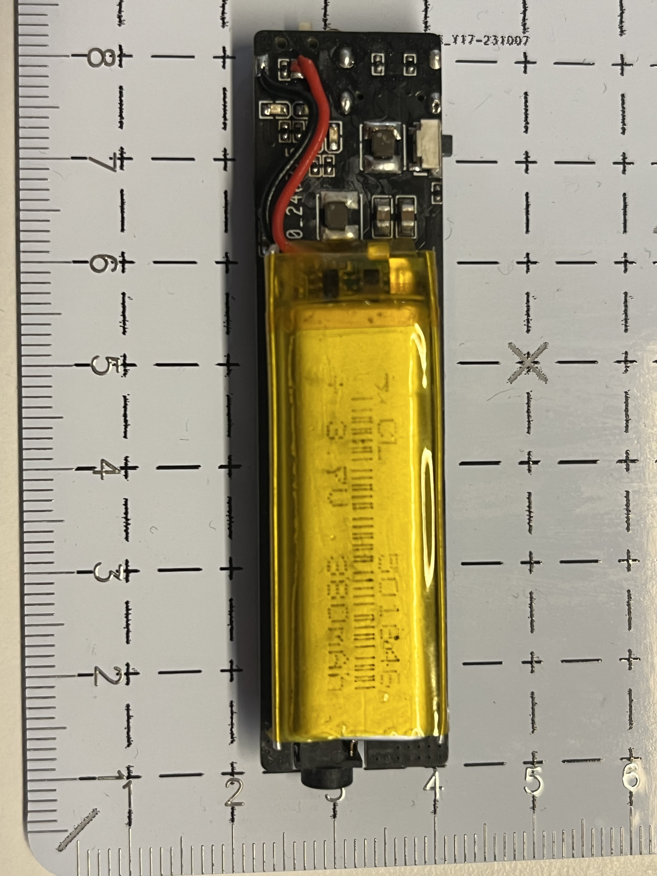
4. Use a standard 3.7V lithium battery and a 4056 chip for charging. Choose a model similar in appearance; I used the 501646.
Schematic Design Notes:
1. The QCC3034 module uses only one button for pause; a long press disconnects. The rest is the same as the reference diagram.
2. The PCM5102A uses the reference circuit directly, with the output RC filter removed.
3. The LM4881 has a modified gain compared to the reference circuit. My personal testing suggests a suitable gain of 0.5; I do not recommend exceeding 0.7, as insufficient output power can easily cause distortion.
4. The battery uses the 4056 reference circuit directly.
5. Power Supply Section: The battery directly powers the QCC module. One ME6211-3.3 transistor powers the digital power supply of the PCM5102A, and another ME6211-3.3 transistor powers the analog power supply of the PCM5102A and the LM4881. Grounding is implemented. The inductor shown in the schematic only serves as a solder pad; a ferrite bead is recommended for the actual component.
Improvement Directions:
If you wish to further improve, the following suggestions are made:
1. Change the LM4881 power supply to a battery-driven DC-DC boost followed by an LDO step-down to 5V. This would allow for approximately 110mW of power output at 32 ohms impedance.
2. The input and output impedance of the analog section from the PCM5102A to the LM4881 can be further optimized.
PCB Design Notes:
1. The overall board design is based on the width of the QCC module. Considering the battery selection, the length and width can be further optimized, but the optimization space is limited.
2. I only made two layers here because I wanted to utilize the black PCB. Ideally, it should be four layers to house the signals on the inner layers.
3. Because of the two-layer design, the signals weren't strictly designed for 50Ω impedance. A four-layer design would allow for further optimization.
4. The antenna's current placement is a compromise. It shouldn't be placed parallel to the analog section, but based on the current performance, there's no noise during playback. The Bluetooth 2.4G band shouldn't theoretically affect the analog signal.
5. There are currently several traces under the QCC module, but these aren't high-frequency signals and won't have any impact. If you have the capability and spare resources, you can optimize them. I removed some unnecessary pads on the QCC for easier routing and added silkscreen for insulation.
6. Regarding the DRC of the PCB in the current project, I'm too lazy to change the rules; just ignore it if it doesn't need to be added.
Improvement directions:
If you wish to continue improving, the following suggestions are made:
1. Change the PCB from 2 layers to 4 layers, and place all signals on the inner layers;
2. Under the premise of changing to 4 layers, route all signals according to impedance;
The physical demonstration
photos are of poor quality, please forgive me; the picture shows my first version, which has a flying lead. If the design file is correct, it can be directly submitted to the board;

Notes on
QCC module selection:

Cost estimation:
Main components
TB (default refurbished)
LCSC
QCC3034
29 + postage 5.5 (Anlang Technology)
None
PCM5102A
5
27
LM4881
2
10
AN9520
1
1.8
TP4056/USBLC6/MSK12C02/Others
5
5
Total
approximately 50
Approximately 90
PDF_Portable Bluetooth Decoding Headphone Amplifier.zip
Altium_Bluetooth Portable Decoding Headphone Amplifier.zip
PADS_Bluetooth Portable Decoding Headphone Amplifier.zip
BOM_Bluetooth Portable Decoding Headphone Amplifier.xlsx
95437
NRF52840_DK_V1.0
The NRF52840 development board is pin-to-pin compatible with the official board, allowing you to run official code directly.
The NRF52840 development board is pin-to-pin compatible with the official board, allowing you to run official code directly. Please see the attached BOM (Bill of Materials).
nRF52840_DK_V1.1 Development Board BOM List.xlsx
PDF_NRF52840_DK_V1.0.zip
Altium_NRF52840_DK_V1.0.zip
PADS_NRF52840_DK_V1.0.zip
BOM_NRF52840_DK_V1.0.xlsx
95438
#Bootcamp# A Simple Digital Oscilloscope Project Based on GD32
A Simple Digital Oscilloscope Project Based on GD32
This is a simple digital oscilloscope project based on the GD32 microcontroller. It's in the beginner's section, so the hardware details won't be explained in detail.
Please see the readme file in the Doc folder in the attachments for specific instructions.
I prefer using UTF-8 encoding in Keil to ensure compatibility with various needs, so I generally don't include Chinese comments in the project. The English comments are similar to construction site jargon, and I think it's necessary to write a separate document to explain some aspects of the project. This project is based on the open-source code by Mr. Chen from JLCPCB, with some modifications. The open-source website is: https://gitee.com/chen11232/GD32E230-Oscilloscope.
Let's start with main.c, which includes clock configuration, LED pin initialization, and KEY pin initialization.
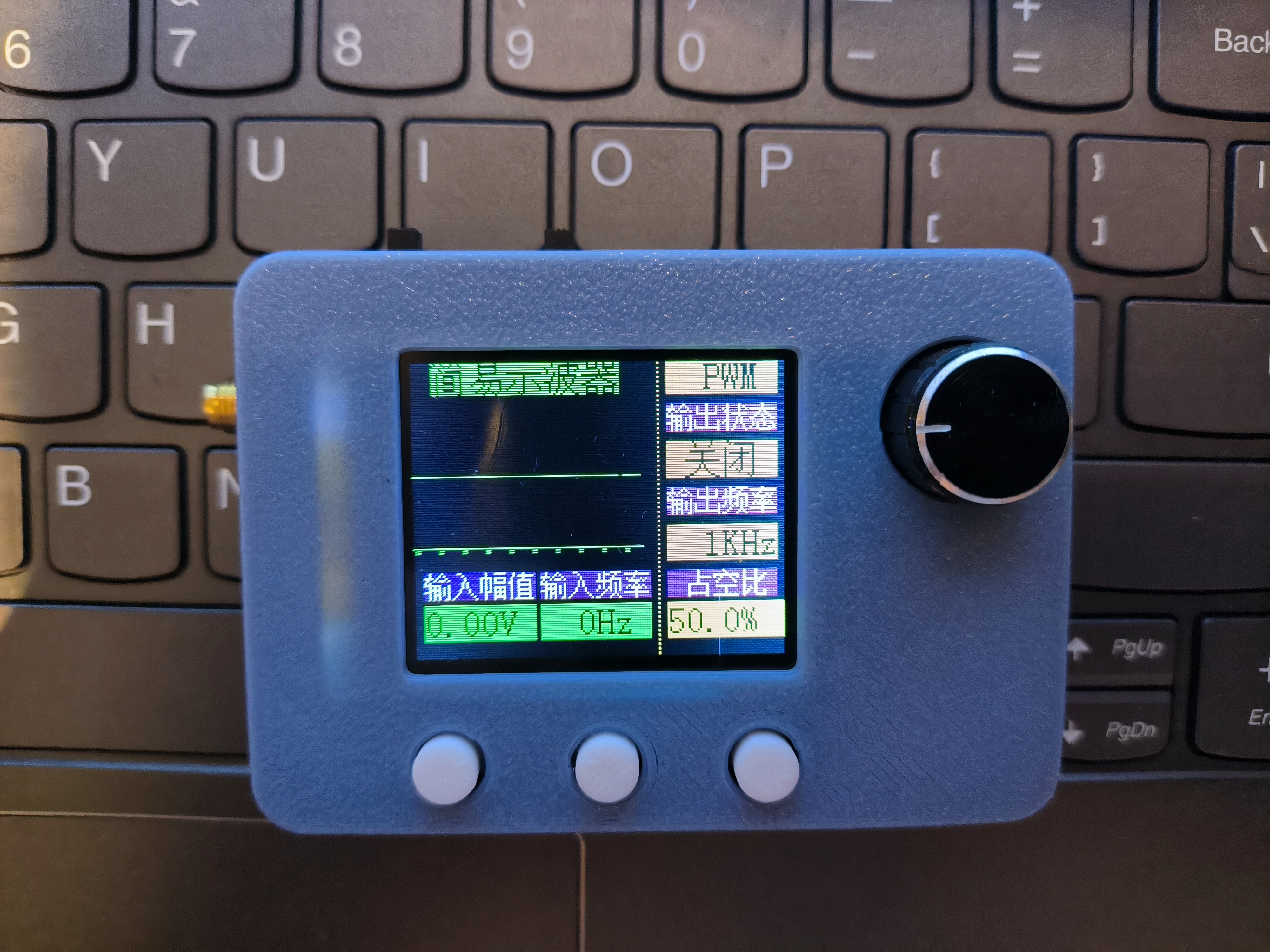
After the initialization function, a JLCPCB image is added as the standby screen. Toggling KEY1 skips this screen and enters the normal program. The header file containing the image has been removed from files with the "Simplified" suffix, which may shorten the download time.
The standby screen program is implemented as follows:
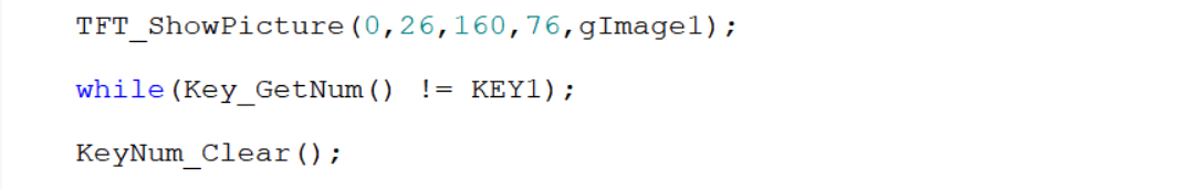
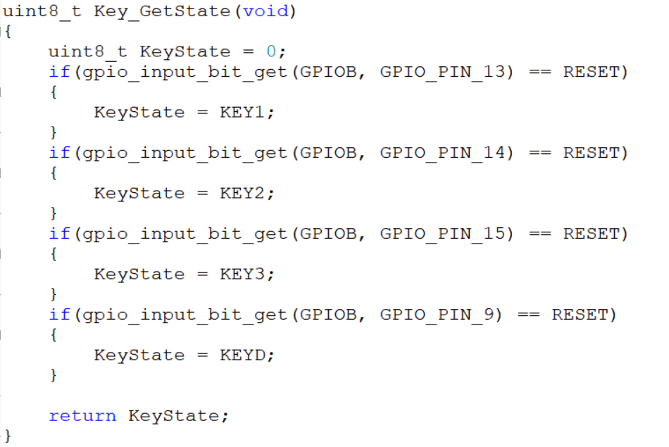
LED pin initialization and KEY pin initialization are relatively basic and will not be discussed in detail. Of particular note are the `Key_GetState()` and `Key_GetNum()` functions in `Key.c`. `Key_GetState()` returns the key value corresponding to each key pressed. For example, if key 1 is detected as pressed (GPIO PB13 pin is low), the key state is returned as the return value. In `Key_GetNum()`, the previous and current key states are read. If a key is always pressed, the current key state will never be zero, and the function returns the previous value of `keynum`. Only when a key is released does the function begin to determine which key was previously pressed based on the previous state. For example, if the current key state is 0 and the previous key state was 1, then KEY1 can be considered pressed, and the key value of KEY1 is returned.


Serial port initialization and external interrupt initialization are also quite basic and will not be discussed in detail. It's worth noting the external interrupt function 4-15 (void EXTI4_15_IRQHandler(void)) in main.c. This function adjusts the PWM output frequency, duty cycle, and ADC sampling time of the GD32 chip based on the current key value and the rotation state of the rotary encoder. Within the function, the variables cnt1 and cnt2 store the clockwise (counterclockwise) rotation of the rotary encoder, primarily to prevent misjudgments.

Optional values can be found in the gd32e23x_adc.c file by pressing Ctrl+F in the project, entering ADC_SAMPLETIME_239POINT5 in Find what, looking in the Current Project dropdown, and clicking Find Next at the bottom of the window. The optional values can be found in the gd32e23x_adc.c file.
I haven't modified the ADC, FREQ related functions, or screen initialization, so I won't go into detail. For more information, please refer to the relevant videos on software by Bilibili user 立创EDA (LICHENG EDA) and the Oscilloscope Training Camp.
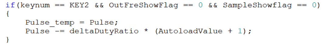
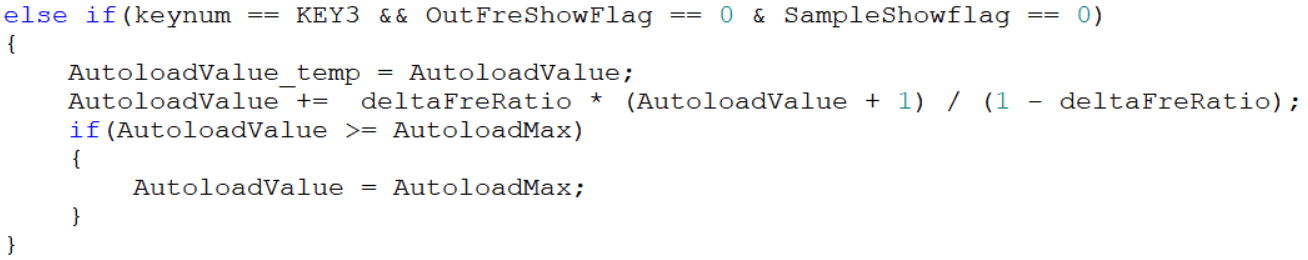
PWM initialization is quite basic and won't be discussed further. It's worth noting that I defined the functions `PWM_PulseAdjustment()` and `PWM_FrequencyAdjustment()`, which are used to calculate the duty cycle and frequency of the output PWM wave. In the `Key_ControlPWM()` function, the PWM output is controlled by checking if `Timer14flag` is 0 to enable or disable Timer14. This flag is controlled by external interrupt functions 4-15. `ONflag` and `OFFflag` prevent frequent refreshes of the display state; the display is refreshed only after the first change in `Timer14flag`, and then the previous display state is retained. `Pulse_temp`, `AutoloadValue_temp`, and `SampleTime_temp` are defined to store the `Pulse`, `AutoloadValue`, and `SampleTime` values of the previous state, respectively. The screen is only refreshed when `Pulse`, `AutoloadValue`, and `SampleTime` change. It's also worth noting that a maximum and minimum output frequency are set, with a minimum of approximately 16Hz and a maximum of approximately 40kHz. After reaching the minimum value, rotating the rotary encoder counterclockwise while in KEY3 state will trigger a screen prompt with a 3-second delay. The input frequency and amplitude will only refresh after the prompt disappears. The prompt appears only once, and rotating the rotary encoder is ineffective while in the prompt state; the output frequency can only be adjusted normally after the 3-second delay.
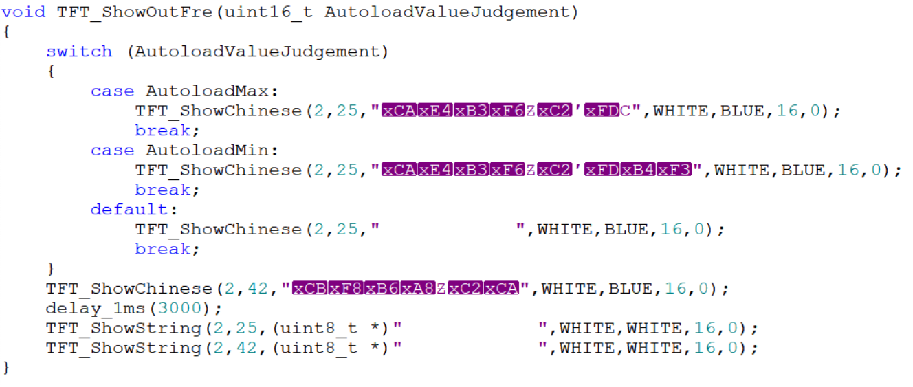
The garbled characters are due to initially using GB32 encoding, which was later changed back to UTF-8. Therefore, it's crucial to develop good coding habits and maintain consistent encoding formats. The same applies to sampling time; changing the sampling time will trigger a prompt, and the sampling time can only be changed after the prompt ends. The Key_ControlPWM() function adds the functionality to display changes on the screen when the sampling time changes. The last two lines are spaces used to refresh the screen and display the sampling time prompt.
This project does not use Chen's Oscilloscope structure variable; therefore, most parameters are passed directly using global variables in main.c, which is a poor practice.
Important Notes: My programming contains numerous bugs due to oversights. If anyone sees this post and burns my program, please leave a comment if you encounter any bugs. I will attempt to fix them when I have the time and energy, and upload a modified version. This is why the uploaded program is labeled V1 and V2. Thank you!
The main problem I encountered was that initially, when using an oscilloscope probe with only 10x attenuation as the input probe, I couldn't measure the frequency and voltage correctly. Using a probe with selectable 1x and 10x attenuation resolved the issue.
FinalProjectV1.rar
FinalProjectV1-Simplified.rar
DemonstrationVideo.mp4
PDF_#Training Camp# Simple Digital Oscilloscope Project Based on GD32.zip
Altium_#bootcamp# Simple Digital Oscilloscope Project Based on GD32.zip
PADS_#Training Camp# Simple Digital Oscilloscope Project Based on GD32.zip
BOM_#Training Camp# Simple Digital Oscilloscope Project Based on GD32.xlsx
95439
Bluetooth serial port
HLK-B40-based wireless serial port module
To access the AT module, pin PC5 needs to be briefly grounded.
PDF_Bluetooth Serial Port.zip
Altium_Bluetooth_Serial_Port.zip
PADS_Bluetooth Serial Port.zip
BOM_Bluetooth Serial Port.xlsx
95440
electronic


 京公网安备 11010802033920号

 SMR10183H100A01L4BULK


