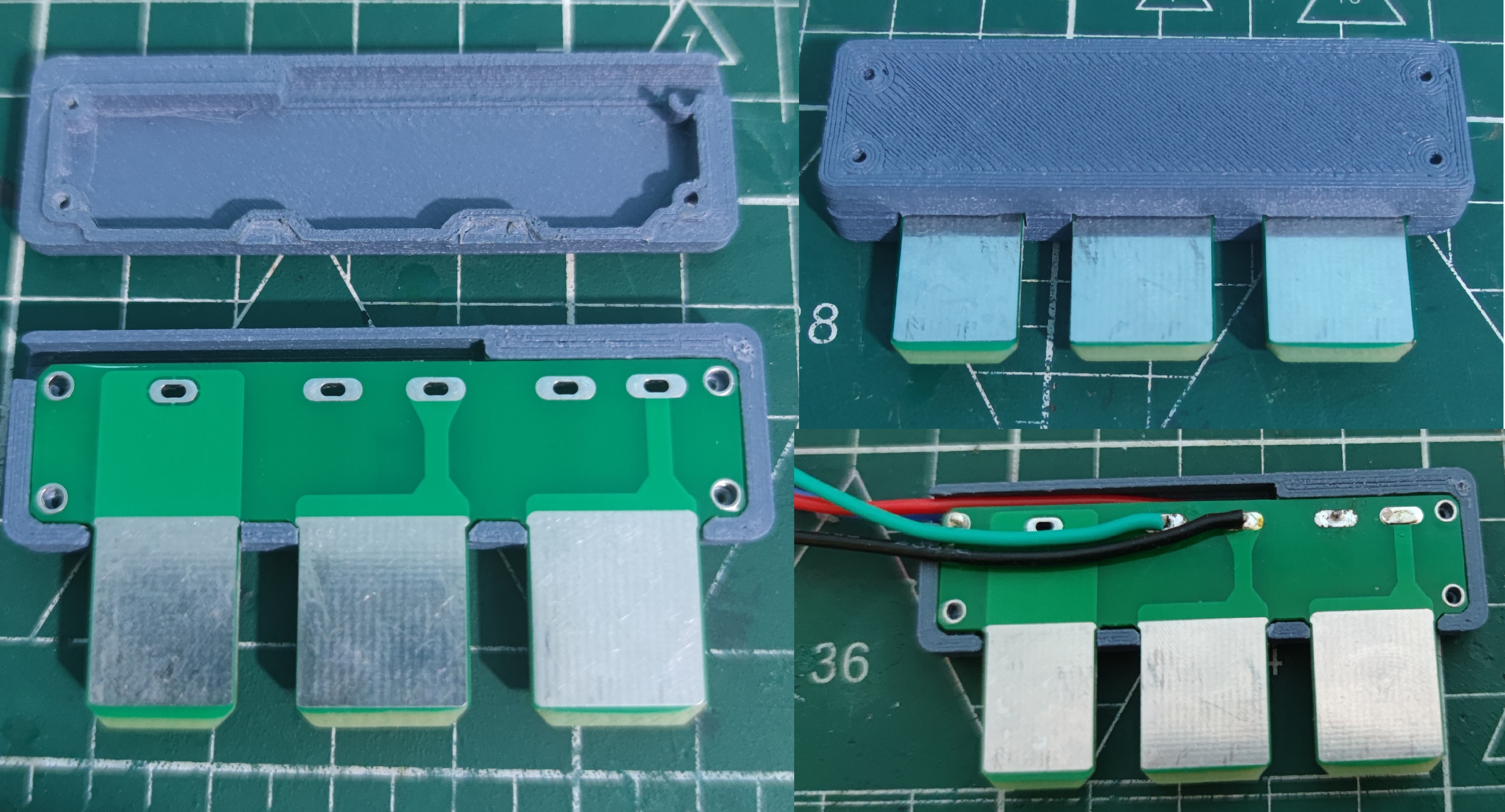
This is a finished product online; you can search for the price yourself. The actual internal structure is relatively simple, and the unit price is quite high, probably because demand is low.
So I made one myself, as shown in the picture below.
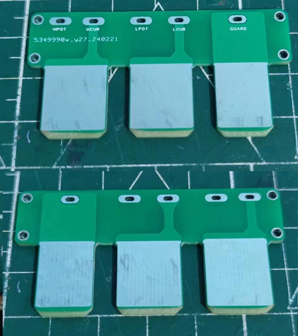
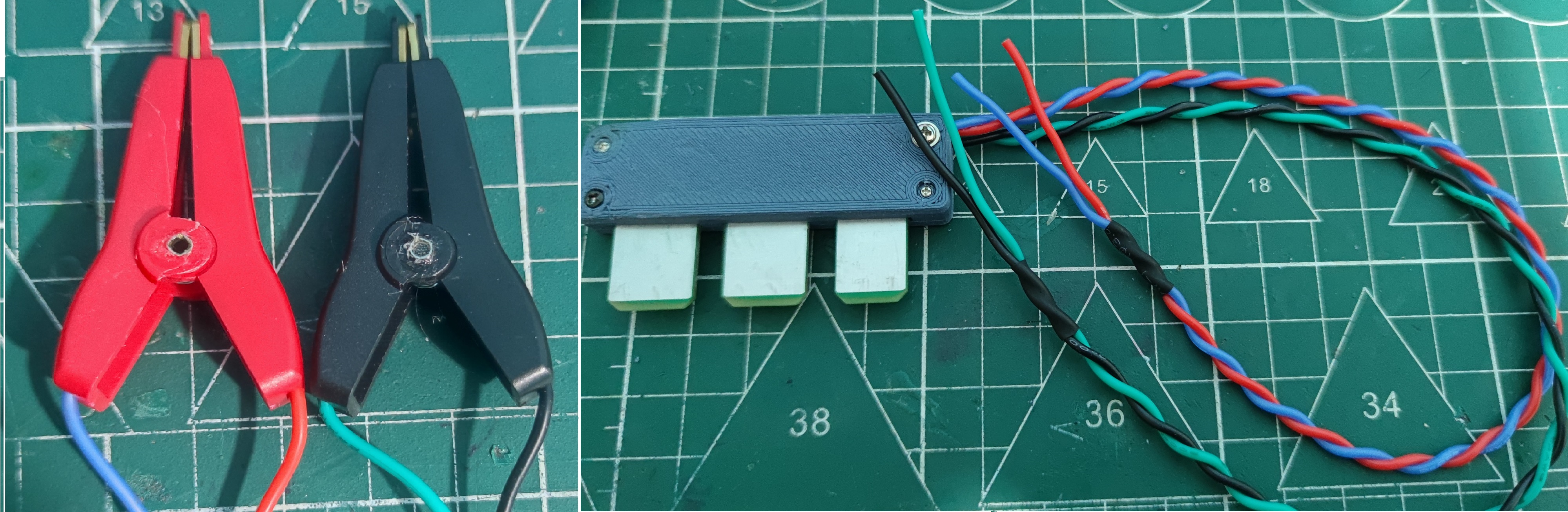
I made the PCB board based on the opening size of this handheld power bridge, and optimized it based on this finished product, adjusting the size and making a shell, which can be 3D printed.
The bottom of the insert can be sanded to create a slope for easier insertion.
PS: It's best to sand the edges of the insert as well to prevent insulating varnish from remaining. The first version's opening area didn't extend beyond the frame, resulting in insulating varnish on the insert's edge. The insert and the handheld power bridge's spring contacts had poor contact, but it wasn't visible to the naked eye. Charlie took a long time to find the cause. A narrow strip of green insulating varnish on both sides protruded a few tenths of a millimeter above the copper foil, preventing the spring contacts from making contact with the copper foil. The PCB opening method has been changed, but it hasn't been tested yet; it should be fine now.
The wiring method is shown in the picture: the two leads of one insert connect to the two copper pieces of a clip. The bottom is for the shielding layer; it's optional.
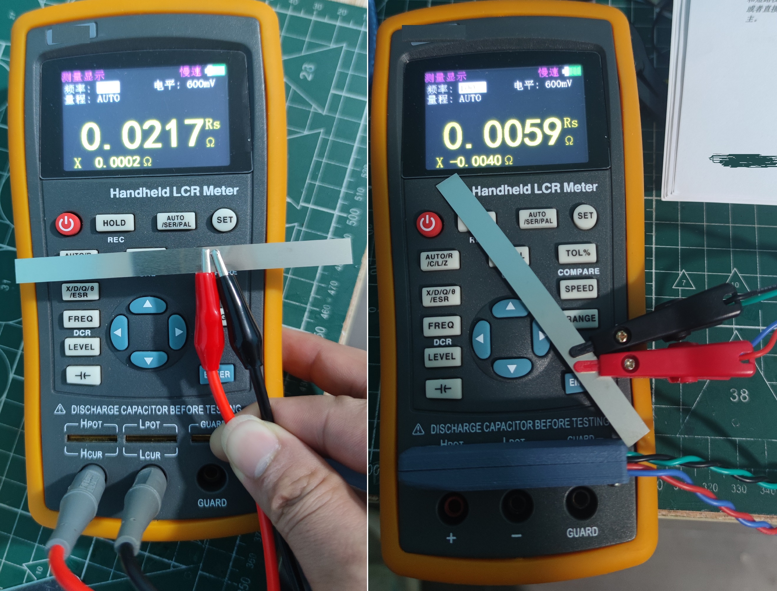
The testing accuracy is much better than the included two-wire alligator clip. The accuracy can be improved by about an order of magnitude.
PS: This nickel strip measured about 0.5m ohms with a battery internal resistance meter, while the bridge circuit is an order of magnitude larger. The two have different ranges, hence the difference in accuracy. This bridge circuit has a minimum resistance range of 200 ohms, while the internal resistance meter's minimum range is 2 milliohms. Therefore, to measure small resistances, you still need to buy an internal resistance meter.
This is a microcontroller based on the ESP8226 that controls a stepper motor to achieve mechanical operation.
1. Design Background
In this age of information overload, we often forget the wisdom of the ancients and the beauty of mechanics. However, the background of designing the waterwheel clock reminds us that even in the age of modern technology, we can combine traditional timekeeping methods with network time to create a unique and creative clock ornament. The
ancient waterwheel clock once used the power of water flow to measure time, showcasing humanity's keen observation and creativity in nature. Today, we can synchronize this ancient mechanism with network time and integrate it into modern mechanical design. Through precise calibration with network time, we can create a clock ornament that perfectly achieves time measurement, not only possessing practical functionality but also serving as a work of art, beautifying our living spaces.
This design is not only a tribute to ancient wisdom but also an innovative application of modern technology. It blends tradition and modernity, presenting a unique aesthetic and a spirit of the times. In this design, we can see respect for time and the inheritance of history, while also reflecting humanity's continuous pursuit and exploration of creativity.
2. Requirements Analysis
Network Time Synchronization: Utilizing the ESP-12F module to connect to the network and obtain accurate network time. This ensures the clock ornament always displays the accurate time without manual adjustment. Colored lights create a romantic atmosphere.
Colored light effect: Colored lights are arranged around the clock ornament. By controlling the color and brightness of the lights, a romantic and warm atmosphere is created, making the clock ornament not only a practical item but also a decorative piece.
Stepper motor control: The clock's timekeeping function is achieved by controlling the stepper motor to rotate at a fixed angle according to a certain number of teeth. The speed and rotation angle of the stepper motor can be adjusted as needed to make the clock ornament's timekeeping more accurate and smooth.
Battery life and charging function: The clock ornament is designed with a certain battery life, allowing it to work continuously for a period of time. It is also equipped with a charging function, which can charge the clock ornament via USB interface or other charging methods to ensure its stable operation over a long period of time.
3. Scheme Design
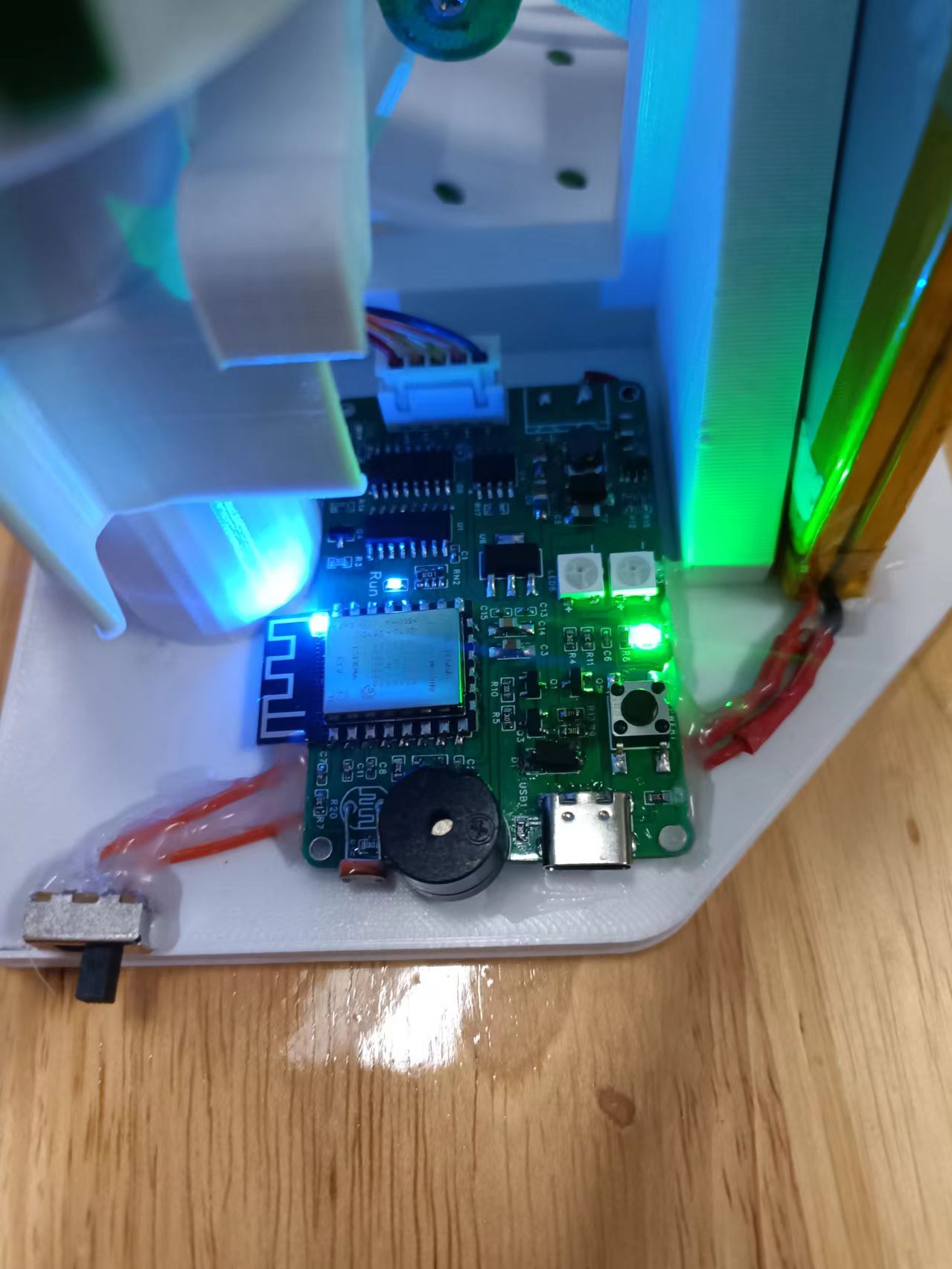
3.1 In this design, the hardware system includes an ESP-12F module microcontroller minimum system, a serial port download interface, a stepper motor, and a TP4056 charger.
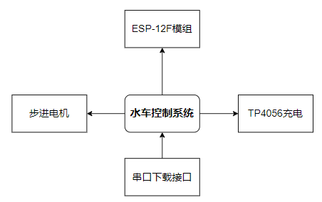
Figure 3.1 Hardware System Structure Diagram
3.2 Minimum System of
the ESP-12F Module The minimum system of the ESP-12F module refers to the necessary components for the microcontroller to function properly and perform its functions. It generally includes four parts: power supply circuit, clock circuit, reset circuit, and download/debugging circuit. This design uses the LQFP144-pin main control chip, and some peripheral circuits are shown in Figure 3.2.

Figure 3.2 Pin Assignment Diagram of the ESP-12F Module

Figure 3.3 Physical Diagram of the ESP-12F Module
3.3 BOOST Boost Circuit
This circuit boosts the battery voltage to approximately 4.86V to prevent system malfunction when the battery power decreases. The chip used is the MT3608, a very common DC-DC power supply chip.
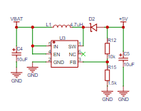
Figure 3.4 BOOST Boost Circuit Diagram
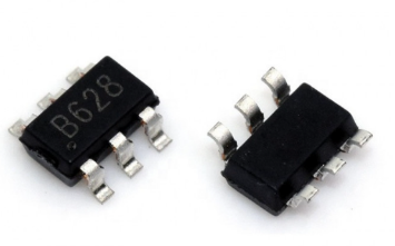
Figure 3.5 Physical Diagram of MT3608
3.4 Reverse Connection Protection and One-Button Power On/Off Circuit
When the battery and USB are powered simultaneously, there will be a short circuit due to overcurrent. This design uses D1 and Q3 to form a reverse connection protection circuit, allowing the USB port to charge the battery while simultaneously powering the system. Q1 and Q5 form a one-button power-on/off circuit. After power-on, the input power Vin charges capacitor C6 to the power supply voltage via resistors R5 and R11. MOSFETs Q1 and Q5 are cut off, and Vout has no output. Power-on state: When the circuit needs to be powered on, pressing switch S1 applies voltage to the gate of the NMOS transistor C1, causing Q5 to quickly saturate and conduct. The gate potential of Q1 is pulled down to near 0V, and Q1 also quickly conducts and saturates, resulting in a voltage output Vout. At this time, Vout, through resistor R2, is applied to the gate of NMOS transistor Q5, maintaining Q5's conduction and forming a self-locking loop. If S1 is not released, Vout will continue to charge capacitor C6, not affecting the power-on state of the circuit. If S1 is released, capacitor C1 discharges to near 0V through resistor R11 and the drain-sink of Q2, preparing the circuit for power-off. When the circuit needs to be powered off, press switch S1 again. Due to the effect of capacitor C6, the gate potential of NMOS transistor Q2 is pulled low to a low level, and Q5 is cut off. After Q5 is cut off, the gate potential of PMOS transistor rises to a high level, Q1 is cut off, and Vout has no output. At this time, switch S1 should be released, and capacitor C6 will slowly charge through resistors R5 and R11 to close to the input power supply voltage. It returns to the initial power-on state.
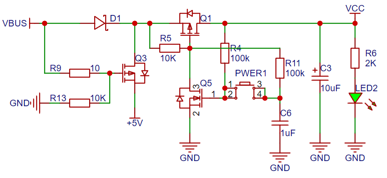
Figure 3.6 Anti-reverse connection and one-button power-on circuit diagram
3.5, Charging circuit
TP4056 is a high-performance single-cell lithium-ion battery constant current/constant voltage linear charger. The TP4056 uses an ESOP8 package and has fewer external components, making it very suitable for portable products and suitable for powering USB power and adapter power.
Based on the special internal MOSFET architecture and anti-reverse charging circuit, the TP4056 does not require an external sense resistor and isolation diode. When the external ambient temperature is too high or in high-power applications, thermal feedback can adjust the charging current to reduce the chip temperature. The charging voltage is fixed at 4.2V, while the charging current can be externally set via a resistor. When the charging current drops to 1/10 of the set value after reaching the final float voltage, the chip terminates the charging cycle.
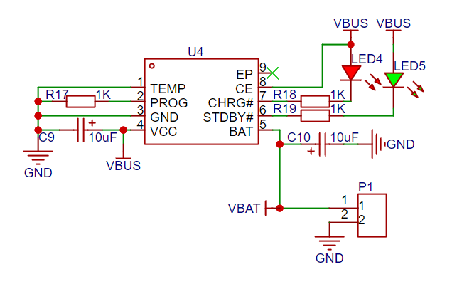
Figure 3.7 shows the charging circuit diagram.
3.6. Stepper Motor Drive Circuit:
The ULN2003 is a high-voltage, high-current Darlington array composed of seven silicon NPN Darlington transistors. The circuit features are as follows: Each pair of Darlington transistors in the ULN2003 is connected in series with a 2.7K base resistor. At a 5V operating voltage, it can be directly connected to TTL and CMOS circuits, directly processing data that previously required standard logic buffers.
The ULN2003 is a high-voltage, high-current Darlington transistor array series, featuring high current gain, high operating voltage, wide temperature range, and strong load-carrying capacity, making it suitable for various systems requiring high-speed, high-power drives.

Figure 3.8 Stepper Motor Drive Circuit
3.7 Automatic Download/Debugging Circuit
In this design, the download interface has a reserved 2*10P horn-shaped connector, which can be used with Jlik, DAP, STlink downloaders or for debugging the microcontroller.

Figure 3.9 Automatic Download/Debugging Circuit Diagram
ESP Series Microcontroller Download Selection
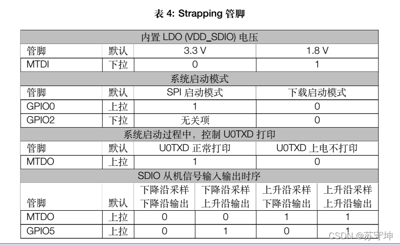
The ESP32 has two startup modes: SPI startup mode (normal startup) and download startup mode. To achieve automatic program download, it is necessary to automatically enter the download startup mode upon power-up. The method is to pull GPIO0 and GPIO2 low simultaneously. Since GPIO2 is pulled down by default upon power-up (IO2 may be used as an SD card or for other purposes, so if a device is connected and the pin is high, download will fail), we can consider only GPIO0. Simultaneously controlling the reset pin (EN) will achieve automatic program download, as follows:
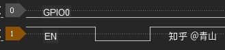
When EN rises from low to high (rising edge), the CPU resets. After reset, if GPIO0 is detected to be low, the CPU automatically enters the download startup mode!
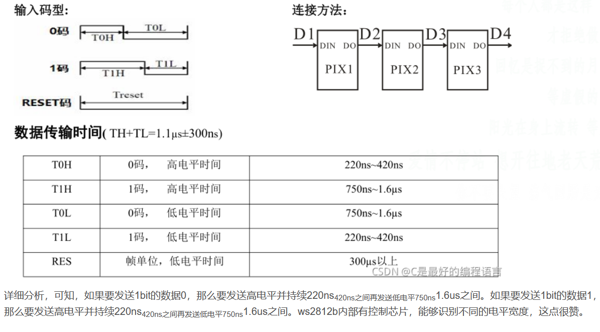
3.8 WS2812REB Color Light Driver Circuit
The WS2812B is an intelligent externally controlled LED light source integrating control and light-emitting circuits. Its appearance is identical to a 5050 LED, with each element representing a pixel. Internally, each pixel includes an intelligent digital interface data latch, signal shaping, amplification, and drive circuit, as well as a high-precision internal oscillator and a 12V high-voltage programmable constant current control section, effectively ensuring high color consistency of the pixel light. The data protocol uses a single-wire return-to-zero (RZ) communication method. After power-on reset, the pixel receives data from the controller via the DIN pin. The first 24 bits of data are extracted by the first pixel and sent to its internal data latch. The remaining data is shaped and amplified by the internal shaping circuit and then forwarded to the next cascaded pixel via the DO port. The signal decreases by 24 bits with each pixel. The pixel employs automatic shaping and forwarding technology, meaning the number of cascaded pixels is not limited by signal transmission speed, but only by the required signal transmission rate.
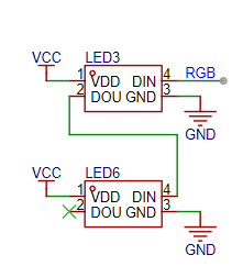
Figure 3.10 S2812REB LED Driver Circuit
. 3.9 Night Detection Circuit:
Night detection is achieved by using a photoresistor and a resistor to divide the voltage.
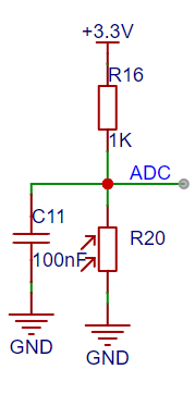
Figure 3.11 3.4 Night Detection Circuit . Figure
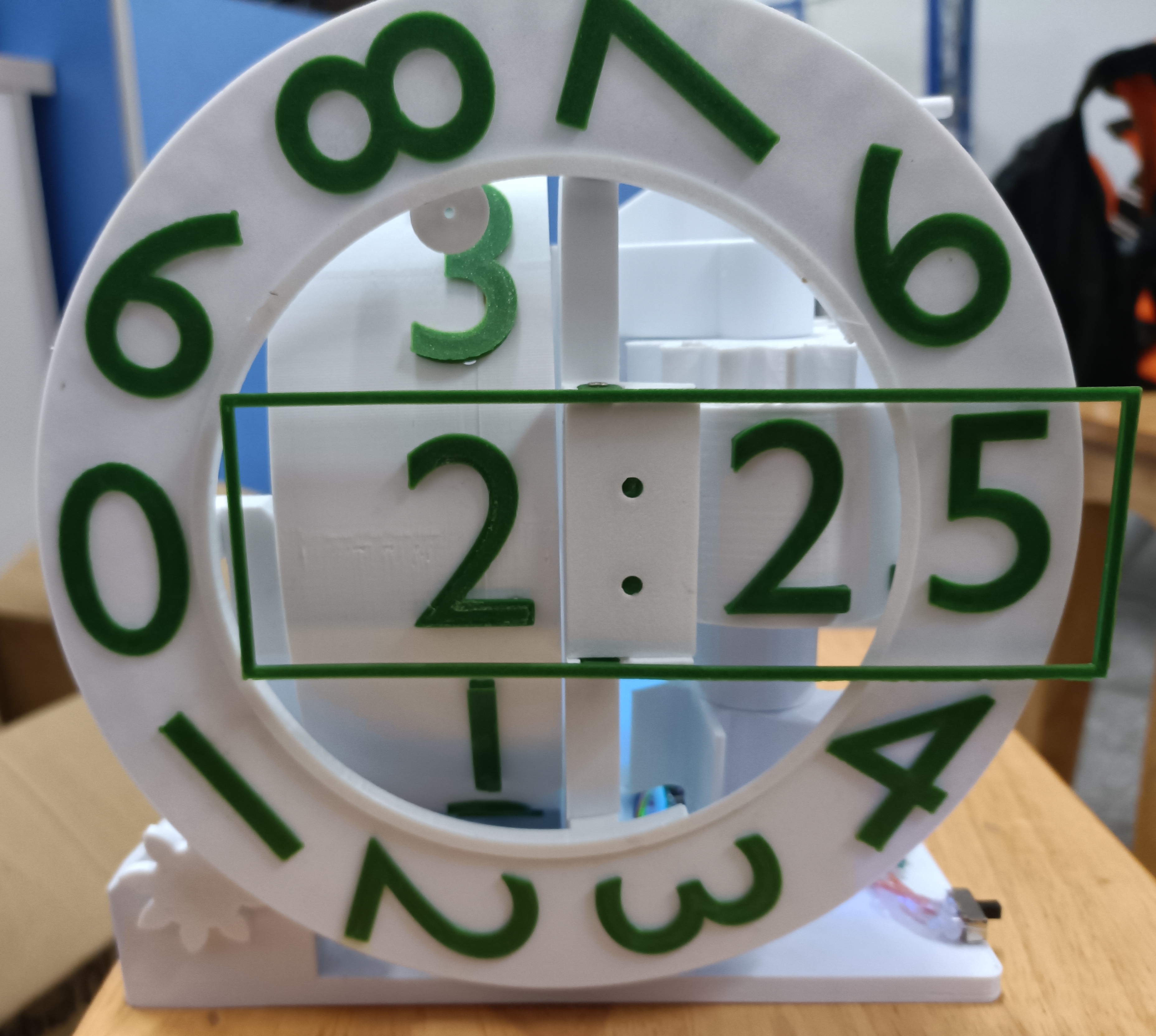
3.10 Physical appearance
model is from T-site: https://www.thingiverse.com/thing:6285769
Nighttime video.mp4
code.txt
PDF_Waterwheel Clock.zip
Altium_Waterwheel Clock.zip
PADS_Waterwheel Clock.zip
BOM_Waterwheel Clock.xlsx
95446
Simple Oscilloscope
Implement a simple oscilloscope function using an STM32F103C8T6 microcontroller with built-in PWM output calibration.
Step 1: Using the reference schematic LAYOU;
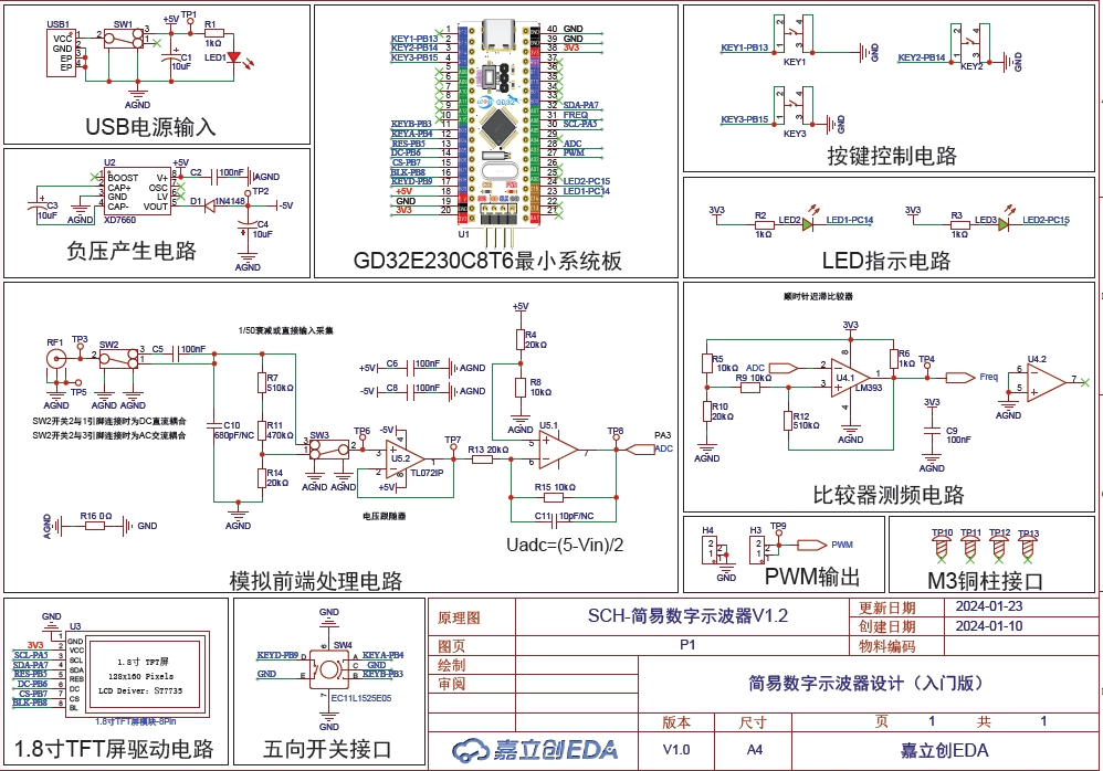
Step 2: PCB prototyping
; Step 3: Material procurement;
Step 4: Surface mount technology (SMT) and debugging;
Step 5: Lessons learned.
osc.mp4
stm32f103c8t6.hex
)6($9%`_R)`1JJI)GF}WMUX.png
PDF_Simple Oscilloscope.zip
Altium_SimpleOscilloscope.zip
PADS_Simple Oscilloscope.zip
BOM_Simple Oscilloscope.xlsx
95448
Licheng Liangshan School Smart Car
This project uses the Liangshan School of Design from LCSC. As a beginner, this is my first time learning to make a small car.
The hardware
consists of a LCSC Liangshanpai GD32F470 main controller,
an RZ7889 motor driven by a DC geared motor,
an ITR9909 infrared module for tracking (software to be improved),
a Bluetooth external plug-in JDY-31
ultrasonic sensor (obstacle avoidance), and an HC-SR04
PCB. The development process followed LCSC Liangshanpai's video tutorials and took approximately 60 minutes. This also forms the chassis.
The software
uses Keil, with rough C programming
using PWM to control wheel speed and differential steering. A Bluetooth app controls the car's lights, forward/backward/steering, and obstacle avoidance mode, allowing it to reverse and then turn before moving forward again upon encountering an obstacle. The development
was primarily based on Lark documentation and Bilibili videos. During coding, an issue arose where the chip could not be programmed (compilation was normal, but the chip did not work after programming). This problem was solved using the provided project template. Two short videos of the initial setup
are provided : https://www.bilibili.com/video/BV1Lj411L7jj . Finally, I would like to thank LCSC for its efforts in the open-source community and for providing excellent development boards and high-quality learning resources. This is my first time open-sourcing a replica project. If there are any errors, please point them out.
PDF_LCSC Liangshan School Smart Car.zip
Altium_LCSC Liangshanpai Smart Car.zip
PADS_LCSC Liangshanpai Smart Car.zip
BOM_LCSC Liangshanpai Smart Car.xlsx
95450
ESP32_Downloader
The ESP32 serial-to-USB circuit is used for downloading programs and debugging.
Downloading programs is always a hassle when using ESP32 modules to build circuit boards. Previously, I had to solder pins, remove them after debugging, which was tedious. One day, I saw someone use spring-loaded probes to press against the contacts to download programs, and I immediately thought it was a great idea. So I made this ESP32 programmer. It has six contacts: EN, IO0, GND, TX, RX, and 3V3. The 5V is a lead-out terminal, but I probably won't need it for downloading. Next time I design a circuit board, I just need to leave the corresponding contacts, and I can use it to press against the contacts to download programs.
Snipaste_2024-03-30_03-09-16.png
Snipaste_2024-03-30_03-09-31.png
PDF_ESP32_Downloader.zip
Altium_ESP32_Downloader.zip
PADS_ESP32_Downloader.zip
BOM_ESP32_Downloader.xlsx
95452
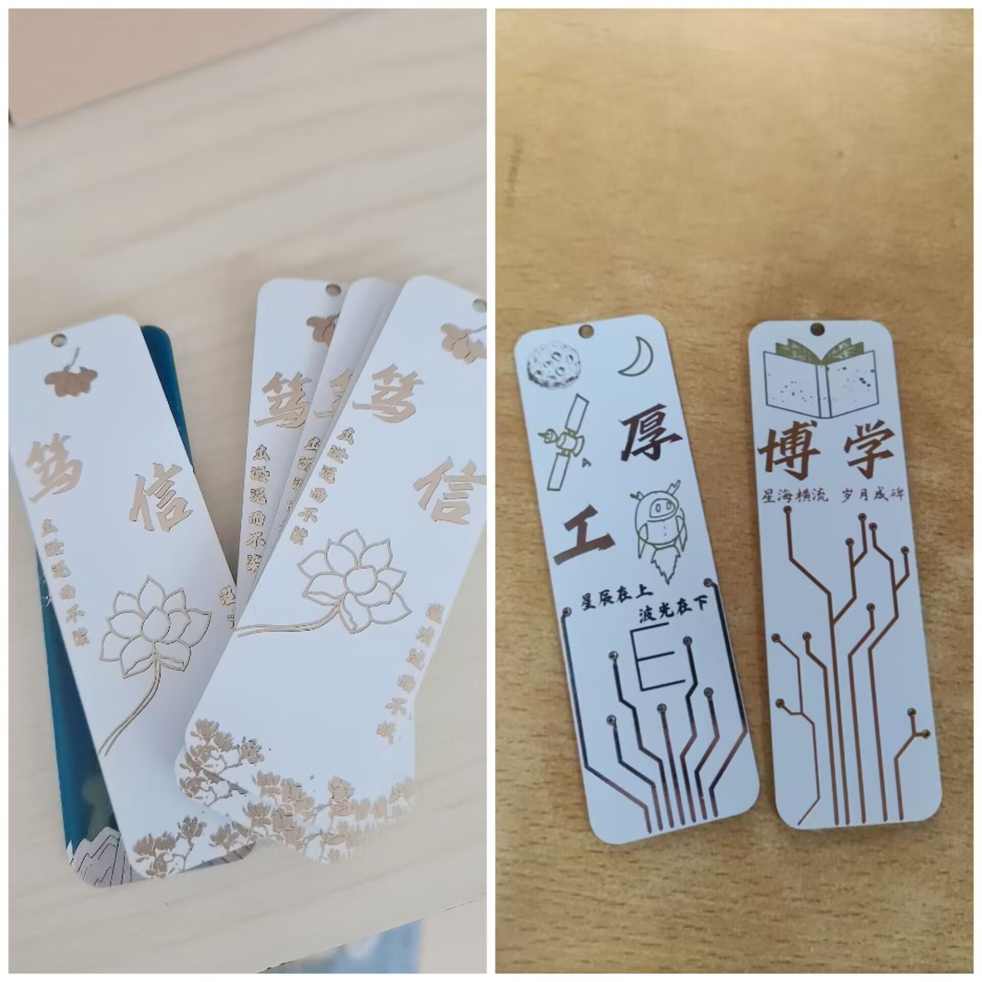
Creative Bookmarks
Southwest University School of Electronic and Information Engineering Cultural and Creative Products: PCB Bookmarks
No schematic diagram available.
Southwest University School of Electronic and Information Engineering Creative Products: PCB Bookmarks. **Firm Belief:** Telecommunications students, in the prime of their lives, are as pure as magnolias and as noble as lotuses, diligently studying and upholding their beliefs. The magnolia and lotus clearly illustrate the telecommunications students' unwavering faith in morality and their career. **Serious Craftsmanship:** A vast universe, accumulating knowledge and skills, striving for excellence, breaking free from established patterns. The rocket e, exploring the universe. This symbolizes telecommunications students using their knowledge of electronic circuits to reach the stars, exploring the cosmos with the waves of electricity. **Erudition:** Learning from many sources, possessing vast knowledge. Above rudition lies the endless reading of telecommunications students; below rudition lies the carving of monuments of time. The knowledge in every book is an indelible mark on this monument. **Humanity-Oriented:** People-centered, venturing into mountains and seas. Endless green mountains, ever-shining stars, a passionate heart climbs to the summit, living up to youthful years chasing the stars. The final version of the PCB bookmark. The cover preview image shows an immersion gold white finish. Note: If using immersion gold white, the board thickness must be 1.6mm; otherwise, it's a less common process and cannot use immersion gold discount coupons. 1.6mm is a bit thick, while 1.0mm is similar to bookmarks on the market, but it cannot be used for immersion gold white. Using tin-plated blue on 1.0mm is acceptable. The circuitry on the back is not yet designed; interested users can try it themselves!
4EE94FFE384B05F77D785A72AE88A6C3.jpg
5AC46842AA769B90401023B4FF3161D1.jpg
LQ7Z)W]8DECB37FYY)`8QTI.png
PDF_Cultural and Creative Bookmarks.zip
Altium_Creative Bookmarks.zip
PADS_Cultural and Creative Bookmarks.zip
95453
electronic

 I made the PCB board based on the opening size of this handheld power bridge, and optimized it based on this finished product, adjusting the size and making a shell, which can be 3D printed.
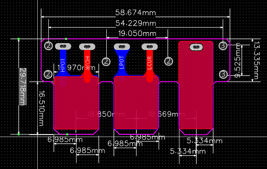
 PS: This nickel strip measured about 0.5m ohms with a battery internal resistance meter, while the bridge circuit is an order of magnitude larger. The two have different ranges, hence the difference in accuracy. This bridge circuit has a minimum resistance range of 200 ohms, while the internal resistance meter's minimum range is 2 milliohms. Therefore, to measure small resistances, you still need to buy an internal resistance meter.


 京公网安备 11010802033920号

 CY3930V208-200BGI


