1. Design Inspiration:
Due to data loss caused by an unexpected power outage, I conceived the idea of purchasing a UPS. Since most high-power UPSs on the market are AC220V, and 12V UPSs have pitifully small capacity and power, and use ternary lithium batteries unsuitable for long-term energy storage and with poor safety, I decided to design a high-power UPS based on lithium iron phosphate batteries, outputting DC12V. This project serves as an intermediate component of the UPS, with the hope of reuse in other projects.
Later, I realized that my need for high power was a misnomer:
my small host's peak power doesn't exceed 60W, and using a high-power UPS under low load conditions would be inefficient and take up too much circuit space; for
devices exceeding 300W, an AC UPS would be more suitable—
all of the above is redundant. However, since I had already researched and purchased the chips, there was no reason to give up halfway, hence this open-source project. 2. Introduction:
Both boards are 86mm*54mm in size, with 3mm rounded corners and a 1.6mm board thickness. This is the common size of an ID card or bank card.
(1) Power board
The power board needs to use an aluminum substrate. The high thermal conductivity of the aluminum substrate will evenly distribute the heat generated by the MOSFET during operation. It can be cooled by air cooling or wall cooling. The board has reserved 0603 NTC resistor positions, which can be used for temperature detection.
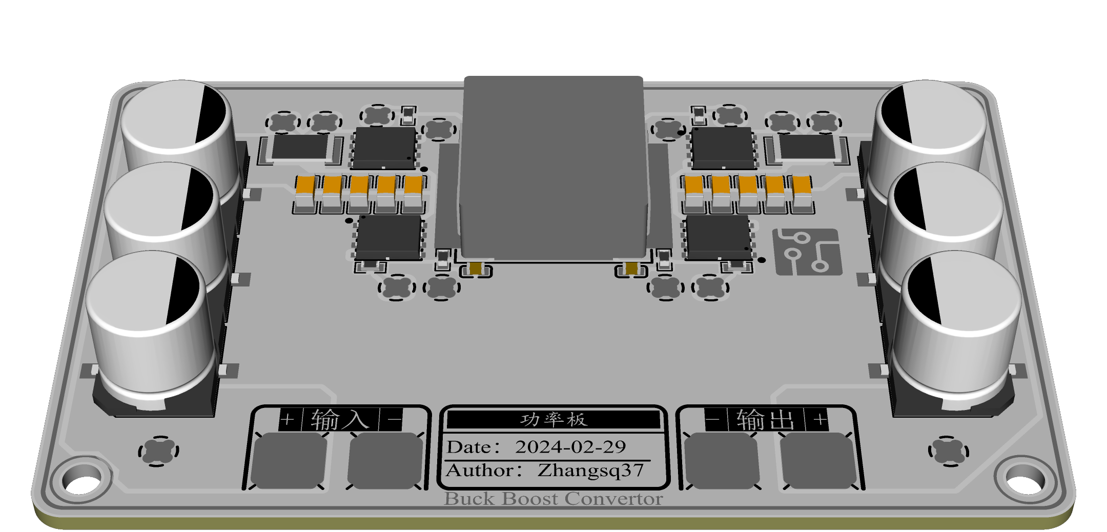
Components used:
Power inductor: 1770 power inductor, please determine the inductance value and saturation current according to the application scenario.
MOSFET: DFN5x6 package, note that Qg should not be too large (CJAC80SN10).
Current sensing resistor: 2512 sampling resistor, its resistance value needs to be modified together with the matching resistor (5mΩ).
MLCC: 1206 (50V, 10uF)
. Surface mount electrolytic capacitor: BD10 package, BD8 package (50V, 220uF) can be selected.
Binding post: 5mm*5mm surface mount binding post. Gate
resistor: 0603.
Screw hole: M3.
Note: The board-to-board connector is a 2mm PINGO probe, but since PINGO probes are indeed expensive, I recommend that you purchase a 2.54mm pitch round female connector. Cut off the injection molded part with diagonal pliers to get a usable connector, which can be male or female. (2) Driver Board:
The driver board is a double-layer board design with reserved slots for capacitors and inductors.
The driver board is not reversible, and all surface-mount components are on the same side. The driver board can be reversed to hide components.
Since the PWM regulation voltage range is [1/6, 1] times Vset, in order to expand the voltage coverage range, the SW pin can be used to control the switching of the MOSFET on and off to switch the range.
The NTC pin can be surface-mounted with a round busbar to continue upward.
The current limiting scheme can be selected by changing the resistor position (supporting up to one PWM regulation).

Components used:
Chip: SC8701, QFN4*4 package
; Resistors and capacitors: 0603
Schottky diode: SOD-323 package (1N5819)
; Pin header: 2*6 pin header, 2.54mm pitch.
N-MOS: SOT-23 package (AO3400) 3. Component parameter calculation reference:
Please refer to the chip datasheet for details:
Output voltage (PWM duty cycle 100%): FB reference voltage 1.22V
Output current: 1.22kV/R, (R is the current limiting setting resistor)
Bootstrap capacitor: 0.1uF
Input and output capacitors: 1uF
VCC gate drive capacitor: 1uF
Current sampling matching circuit: 47pF, resistor: 100000 * current sampling resistor value (500Ω@5mΩ)
For more details, please refer to the datasheet (attachment).
Note: The schematic does not specify the component parameters, so if SMT is required, please modify them to the required parameters. 4. Test video:
Constant voltage, constant current and short circuit test - Bilibili
Control function and high current test - Bilibili
5. Material cost reference:
The main material costs are as follows:
|Material|Quantity|Purchase price (single)|
|:--:|:--:|:--:|
|1770 power inductor|1|3.6|
|Power MOSFET|4|2.4|
|5x5 SMD Terminal Block|4|0.2|
|SC8701|1|2.96|
|1206 Capacitor|10|0.2|
|BD10 Capacitor|6|1.3|
|2512 Resistor|2|0.45|
Other material costs not exceeding 2 yuan, estimated cost (excluding PCB) not exceeding 30 yuan


 京公网安备 11010802033920号

 EL9115


