I. Peripheral Overview
SDRAM: Uses Winbond's W9825G6KH, with a 16-bit bandwidth, 32MB size, 13 address lines, and 16 data lines. Expanded via FMC, version V1, limited by board size and my own capabilities, didn't use equal-length lines, but it still ran. Version V2 had equal-length address and data lines, and only ran at 100MHz in testing; higher speeds haven't been tested.
FLASH: Uses Winbond's W25Q128JVEIQ (other W25Q series packages with WSON-8 can also be used). Both V1 and V2 versions had equal-length data lines and ran normally, but the maximum speed wasn't tested.
EEPROM: Uses JSM24C02 from J.S. Microelectronics (same as AT24C, the only difference is that J.S. Microelectronics offers coupons). All three address lines of the chip are grounded, i.e., addresses 0xA0 and 0xA1 (I accidentally lost the test code for this peripheral, but I tested it before and it ran).
SDMMC: To ensure the development board can use all onboard peripherals simultaneously without conflict, only the SD card can be mounted on SDMMC2. The card slot is connected to the CD (insertion detection pin). However, due to a lack of careful attention, a pull-up resistor wasn't added to the CD pin. Therefore, to use insertion detection, a pull-up resistor needs to be configured internally. (Furthermore, initialization without a TF card will cause failure, so the lack of response during program burning might be due to the card not being inserted.)
USB: The USB interface uses a Type-C female connector. Both CC pins are pulled down with 5.1k resistors. The C to C cable can also be powered (I encountered a product with a floating Type-C CC pin, which was incredibly strange; my C to C PD adapter and power bank seemed unable to power it, and I only discovered the reason after disassembling it). The board does not include a CH340 connector; the Type-C port is only used as a USB interface.
Debug: The board provides 8 pins (4 power, 4 data) as a debug interface. The four data lines are SWDIO and SWCLK for SWD, and PA9 and PA10 for USART1 (pin descriptions are omitted for aesthetic purposes; please add them to the PCB if needed).
SPI LCD: The board has an 8-pin FPC socket as an SPI LCD interface, suitable for driving a 1.14-inch LCD screen (135*240 resolution, through-hole type) with the ST7789 chip. If you want to use an SPI screen with other pinouts, you will need to modify the wiring yourself. Also, although this screen is quite durable (I've reversed the power supply), please carefully check the pinout before using
the MCU. LCD: Since I have two 8080 parallel port screens with a 565 interface (one of which is a 3.5-inch 320x480 Atomic screen driving an NT35310), the onboard interface is a 565 interface, which can directly plug into the 3.5-inch Atomic screen (other sizes should also work, but I haven't tried it). However, this is only for the display interface; the touch interface is different and cannot be used directly. Also, to facilitate future use of capacitive touch, two pull-up resistors and a switch are reserved for later use of software IIC. This part has two interfaces: one is a female header, and the other is an FPC socket. Under -O3 optimization, using FreeRTOS, with an FMC frequency of 240MHz, the full-screen monochrome refresh rate is 170 frames per second (without DMA).
DCMI Interface: Due to the lack of a suitable camera, this part of the design was not verified
. Power Supply: Given the numerous peripherals on the development board and considering extreme cases, a WD1117 (1.35A/3.3V) was used as a linear regulator to reduce the 5V to 3.3V. If not so many peripherals are used simultaneously, a standard AMS1117 (1A/3.3V) can be used. Also, because the H743 is relatively expensive (around 29), unipolar TVS diodes for 3.3V and 5V were designed, and two tantalum capacitors were used. The H743's BAT pin is also connected to the battery and 3.3V via a bat54c. The battery holder is a CR1220.
Interaction Interface: Provides a tri-color LED and three user buttons. The three colors of the LED are controlled by three separate pins, and all three buttons are pulled down by resistors (press to raise).
GPIO expansion: 136 GPIOs were brought out, plus 16 GND and 8 3V3, which made up two 80p headers (the power supply is symmetrical, so it doesn't matter if they are plugged in upside down).
2. Precautions:
There are no instructions on the Debug interface and FPC interface on the PCB. You should either add them or refer to the schematic diagram to make sure you don't connect them in reverse.
The PCB supports DFU download. After powering on, press the BOOT button to set it to 1, then press and release the RST button to complete the reset and restart. Then click the refresh button on the right side of the USB mode in STM32CubeProgrammer. After the USB device appears, click CONNECT to connect.
The V1 version is a two-layer board with a 10x8.4 resolution and supports free prototyping. The V2 version is a two-layer board with a 12x8 resolution and does not support free prototyping (but it is longer and looks better). The V1 and V2 versions are slightly different. The differences are as follows: (1) The reference voltage VREF+ of the V1 version is not directly connected to VDDA, but a 0-ohm resistor is placed as a jumper. The V2 version connects VREF+ directly to VDDA. (2) The LCD backlight pin of version V1 is PB1, and that of version V2 is PB5 (same as Atom, the display part can directly use Atom's routine). Therefore, if you want to use the routine to light up the LCD of version V1, you need to connect PB1 to the 3V3 pin with DuPont wire, or modify the program to set LCD_BL to PB1. (3) The overall wiring of version V2 is more human-like, and the SDRAM, screen header interface and flash data line are all of equal length. As a verification board, version V1 only has equal length in flash, and the wiring is more abstract.
In the SD card routine, FATFS will be used to write files to the card. If it fails to write, the TF card needs to be formatted to FAT format first. Also, if you want to use the CD (insertion detection) pin, remember to pull it up. Do not initialize if it is not inserted.
The BOM table provided for version V1 is slightly inaccurate. The BOM table of version V2 is more accurate, but it is only for reference. You still need to check each item before purchasing.
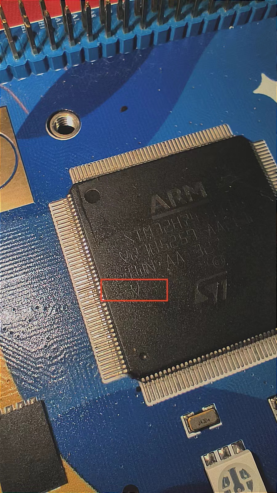
H743IIT6 has two versions, one is V and the other is Y. Version v supports up to 480MHz, while version y only supports up to 400MHz. The version can be identified by the last character of the silkscreen. CubeMX's default configuration is up to 400MHz. To use 480MHz, in the System Core's RCC, change the Product revision in System Parameters to rev.V, and then change the Power Regulator Voltage Scale to Scale 0. The silkscreen identification is shown in Figure
3. Example Descriptions:
Due to limited personal ability, only the following examples are provided. All examples are written using STM32CubeMX and Keil5 based on the HAL library. The parallel LCD driver is ported from Atom, and the SPI LCD driver is ported from a certain boring
DAC_TEST (outputting a cyclically changing voltage on pin PA4).
FreeRTOS: Uses two tasks, one responsible for continuous red and blue screen refresh, and the other responsible for recording and outputting the frame count every second (using a parallel port screen).
FLASH: Use QSPI to perform read and write tests on the FLASH memory, and print the results via serial port (PA9, PA10).
SDRAM: Use FMC to perform read and write tests on the SDRAM memory, and print the results via serial port (PA9, PA10)
. LCD: Use SPI to power on the LCD.
USART: Use QSPI to read and write to the FLASH memory, simultaneously powering on the SPI LCD, and using the internal ADC interface to acquire, calculate, and output the chip's internal junction temperature.
lvgl: Use FMC to drive a parallel port LCD to run a simple LVGL interface (directly using an Atomic 3.5-inch LCD).
SD_T: Use FATFS to operate the TF card via SDIO and write two files.
IV. Appearance

H743IIT6_PORT1.rar
H743IIT6 IO.xlsx
H743IIT6_PORT2.rar
H743IIT6_PORT3.rar
V2 BOM.xlsx
PDF_STM32H743IIT6 Development Board.zip
Altium_STM32H743IIT6 development board.zip
PADS_STM32H743IIT6 development board.zip
BOM_STM32H743IIT6 Development Board.xlsx
96007
Low-power bare board power supply
This example uses the DP2358M to build a low-power 12V 1A flyback secondary-side feedback switching power supply. The structure is relatively simple and suitable for beginners. The schematic diagram is also uploaded. You can export the BOM directly from the file if you need it. For transformer parameters, contact me via WeChat: 15112043894
100~240VAC to 12V 1A switching power supply module
PDF_Small Power Bare Board Power Supply.zip
Altium_low-power bare board power supply.zip
PADS_Small Power Bare Board Power Supply.zip
BOM_Small Power Bare Board Power Supply.xlsx
96009
[Minimum System Board] STC32G12K128 Core Board
Core board design based on STC32G12K128 microcontroller
The chip is STC32G12K128-Beta, and the board has an onboard CH340N, allowing direct program download via a Type-C data cable.
The board includes four LEDs, a 341 reference voltage, a 24C02 chip (IIC), and three buttons.
It is suitable for beginners.
PDF_【Minimum System Board】STC32G12K128 Core Board.zip
Altium_【Minimum System Board】STC32G12K128 Core Board.zip
PADS_【Minimum System Board】STC32G12K128 Core Board.zip
BOM_【Minimum System Board】STC32G12K128 Core Board.xlsx
96010
USB 2.0 expansion dock
No software debugging required, this simple and easy-to-use USB docking station with one input and four outputs is especially suitable for freshmen.
1. Chip circuit

2. Input circuit

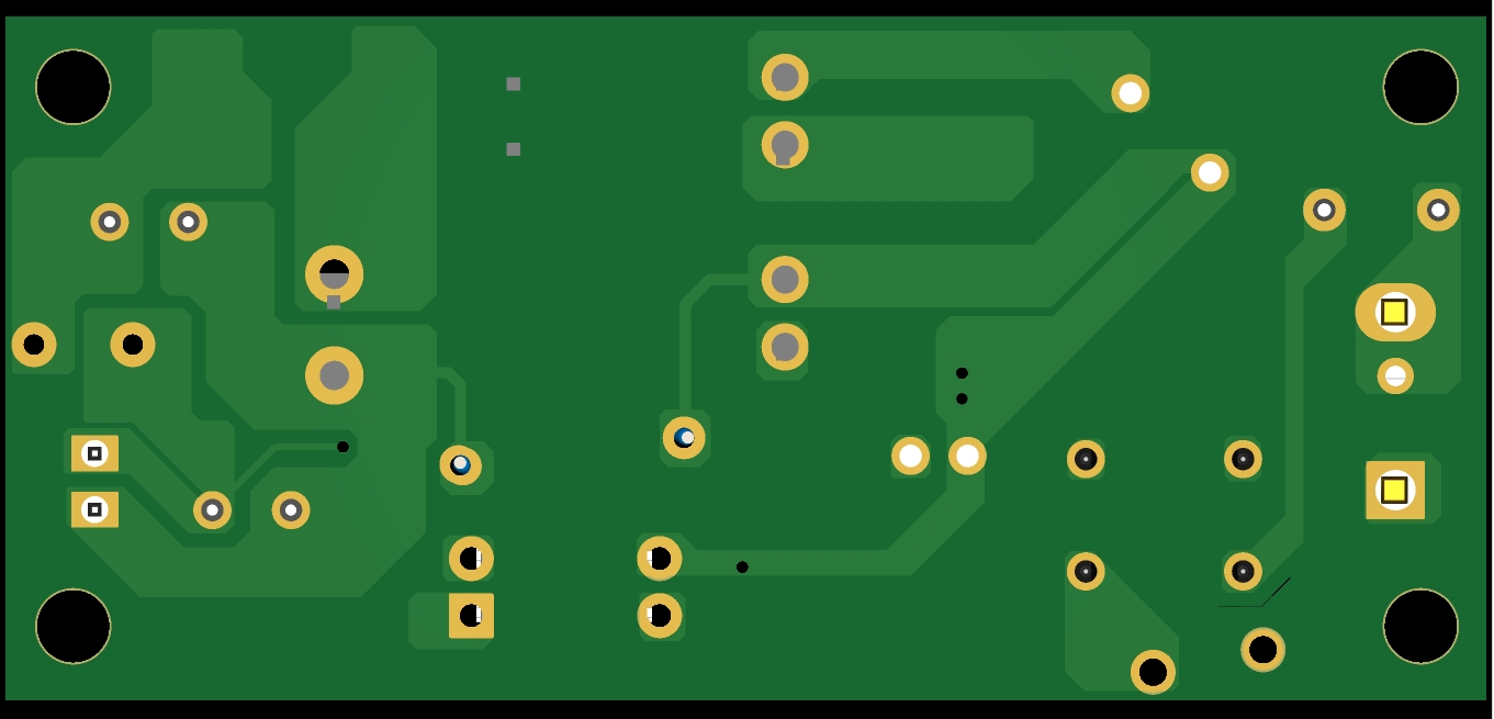
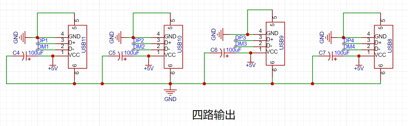
3. Output circuit
Note: 1. When routing the USB data lines DM (D+) and DP (D-), differential pair routing is required.
2. The USB male connector pads should be positioned as close as possible to the edge of the board frame.
Gerber_PCB1_2023-11-27.zip
BOM_Block_PCB1_2023-11-27.xlsx
C192893_624110D24898D57AAC785E3DF98EA862.pdf
PDF_USB2.0 Dock.zip
Altium_USB2.0 Dock.zip
PADS_USB2.0 Dock.zip
BOM_USB2.0 Dock.xlsx
96011
STM32F103ZET6 Core Board Verification
STM32F103ZET6 core board
The STM32F103ZET6 core board features a download port and a serial port, using DAP-link for downloading.
It includes 3.3V and 5V power indicators, as well as two program running indicators.
The core board contains three buttons: a reset button, two function buttons, and EEPROM, FLASH, and SD card modules (not yet verified). Currently, program downloading works without issue.
The connection pins are the same as those on the Zhengdian Atomic Elite board.
PDF_STM32F103ZET6 Core Board Verification.zip
Altium_STM32F103ZET6 core board verification.zip
PADS_STM32F103ZET6 core board verification.zip
BOM_STM32F103ZET6 Core Board Verification.xlsx
96013
∞*∞ Dot matrix screen
A dot matrix screen composed of 1588as/bs dot matrix and 74hc595 cascaded components, which can be spliced together to form an infinitely large screen.
Features:
1. Uses 1588AS/BS dot matrix modules . 2.
Cascaded from 74HC595 modules.
3. Can be spliced together to an infinite size
. 4. Occupies only 3 I/O ports.
5. Optimized circuit design compared to the previous
generation. 6. Compatible with the
Arduino code provided by the previous generation module:
Uses the "ShiftRegister74HC595" third-party library, which needs to be downloaded from the library manager (old version test program, only supports 4 cascaded modules).
The new version code uses the official SPI library, and the test program supports at least 200 cascaded modules (using ESP8266; if using other libraries, it can support approximately 400 modules).
The new version code has poor readability; to understand the code principles, please download the old version.
Note:
Due to the cascading of 74HC595 modules, the scanning time is relatively long, so the maximum number of cascaded modules depends on the speed of the MCU used.
Connection method:
See the open-source project "16*16 dot matrix screen"
module configuration.
Effect: (Scrolling playback)

Dot matrix test.ino
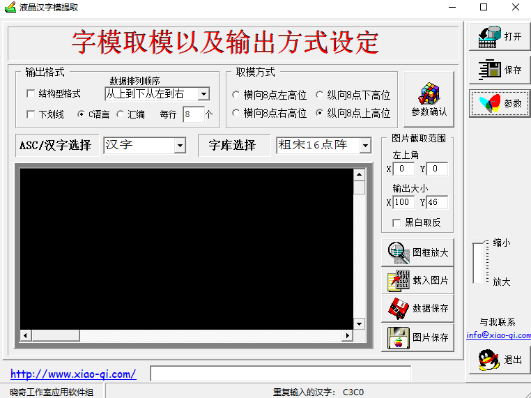
LcmZimoLCD font extraction tool software. (zip)
Dot matrix screen (new version).ino
PDF_∞_∞ Dot matrix screen.zip
Altium_∞_∞ dot matrix screen.zip
PADS_∞_∞ Dot Matrix Screen.zip
BOM_∞_∞ Dot Matrix Screen.xlsx
96014
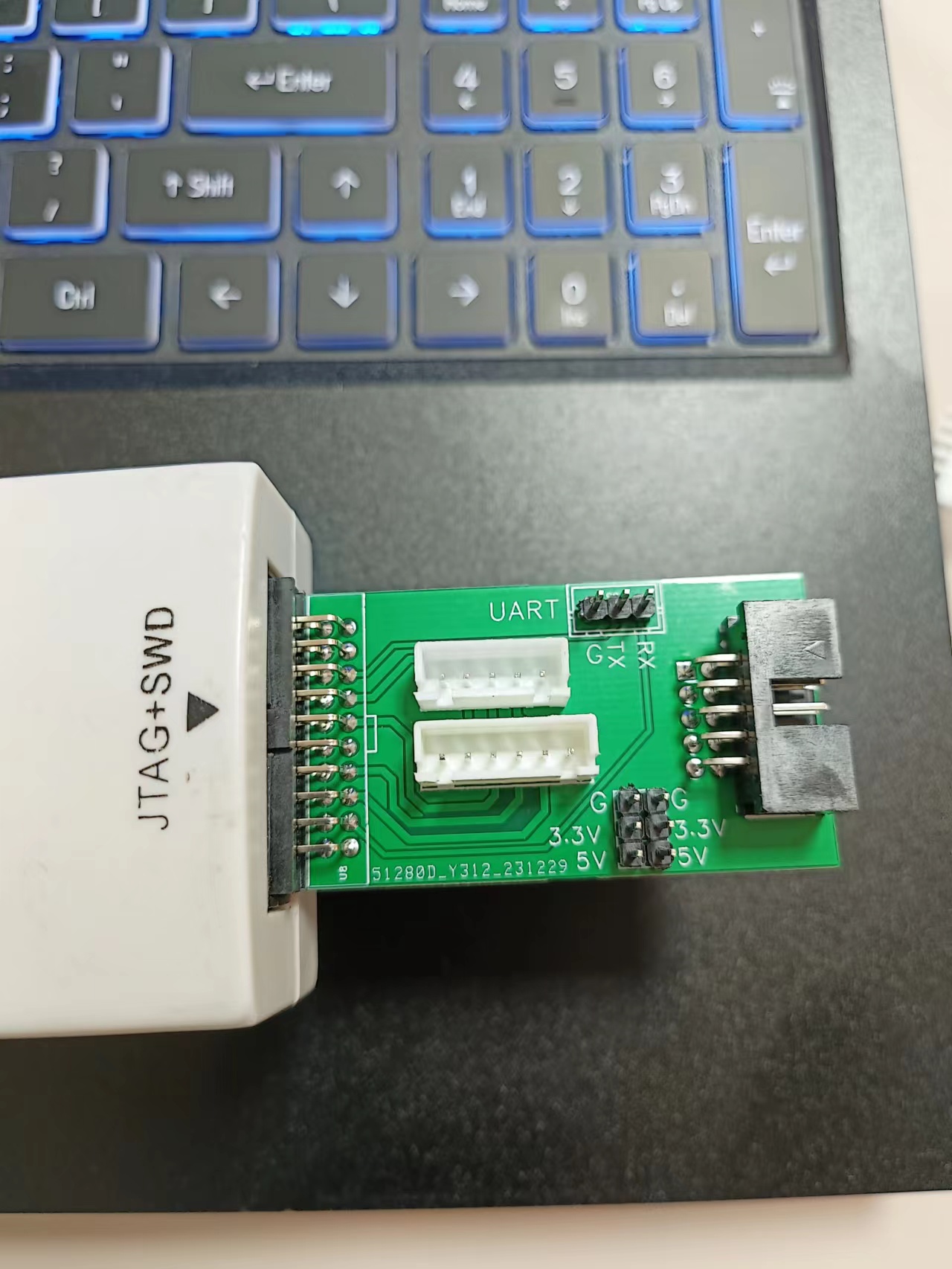
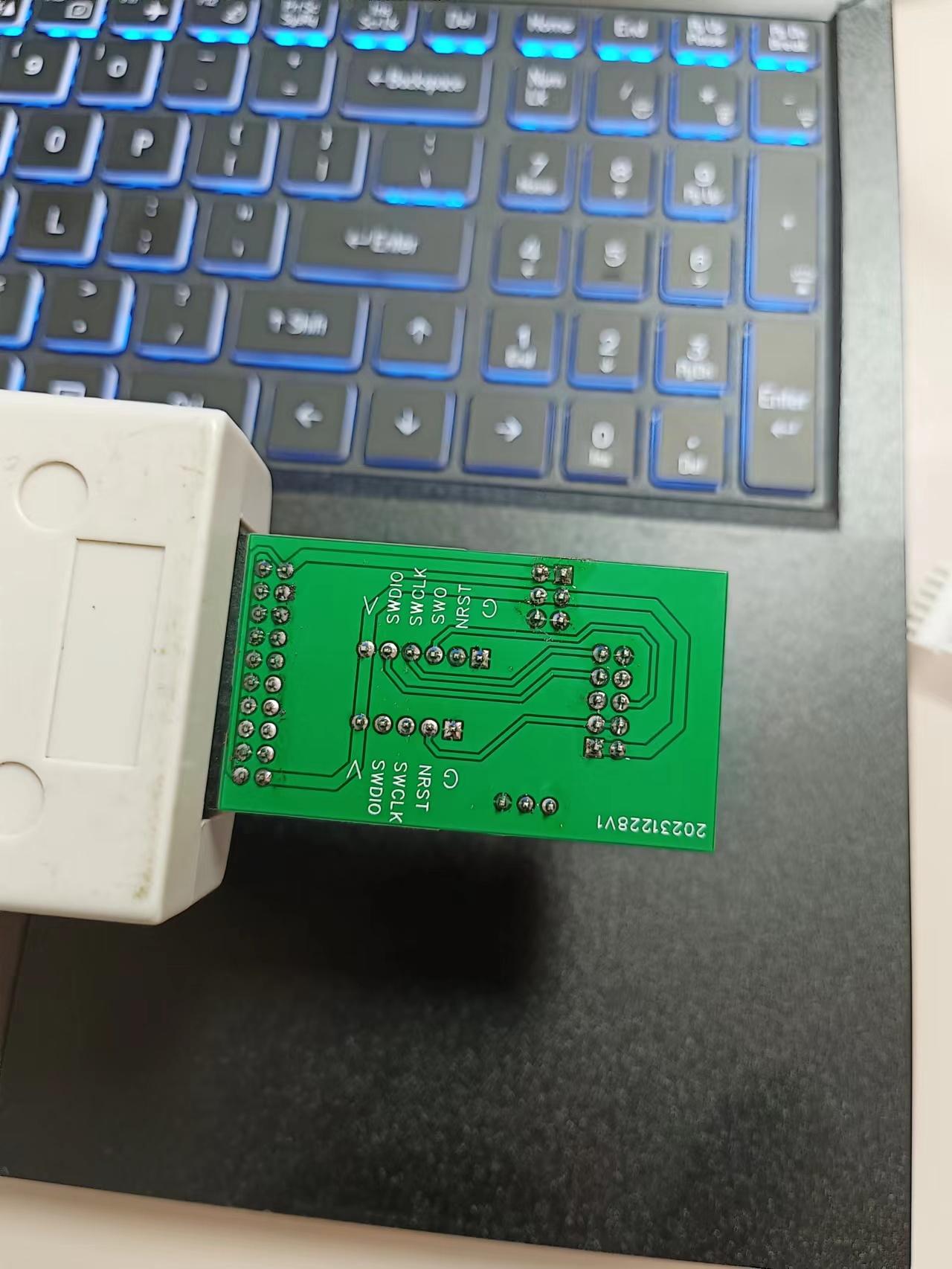
Homemade JLINK interface adapter board
The J-Link adapter board mainly features 5-pin, 6-pin, and 10-pin connectors. It also includes a UART and external power supply. It's relatively simple, but practical.
The J-Link adapter board mainly provides 5-pin, 6-pin, and 10-pin connectors. It also includes a UART and external power supply. It's relatively simple but practical.
One issue arose during testing: I initially intended to bring out the 5V output, but it turned out to be only 3.3V. Otherwise, there were no problems.

PDF_JLINK Interface Adapter Board (DIY) .zip
Custom-made Altium JLINK interface adapter board. (zip)
Homemade PADS_JLINK interface adapter board. (zip)
Homemade BOM_JLINK interface adapter board.xlsx
96016
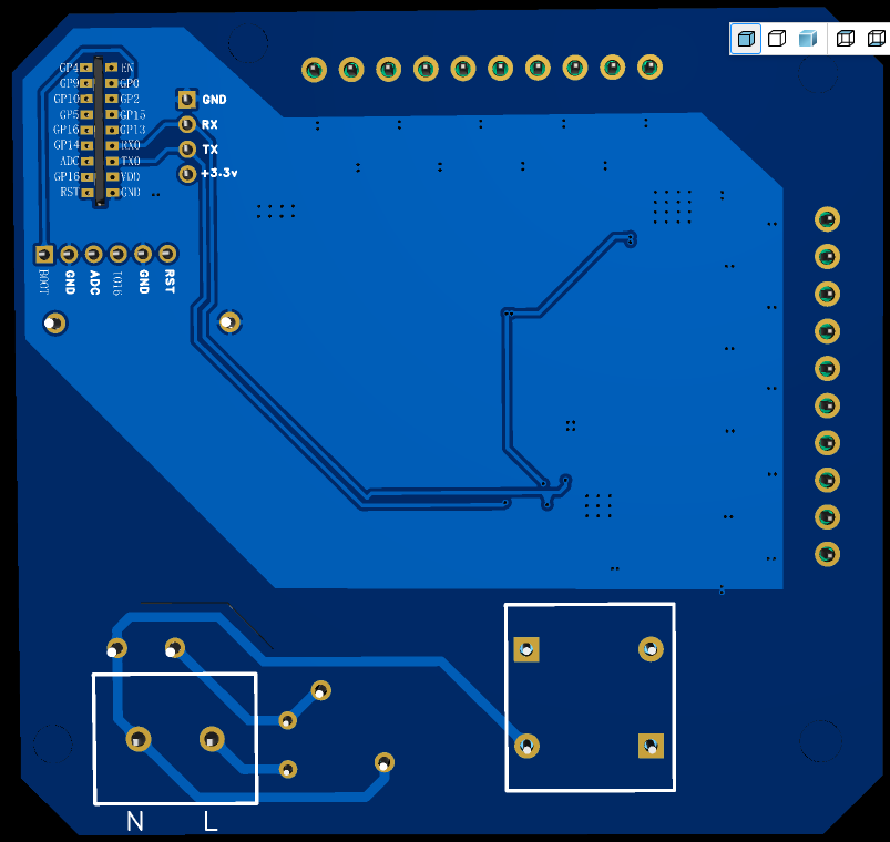
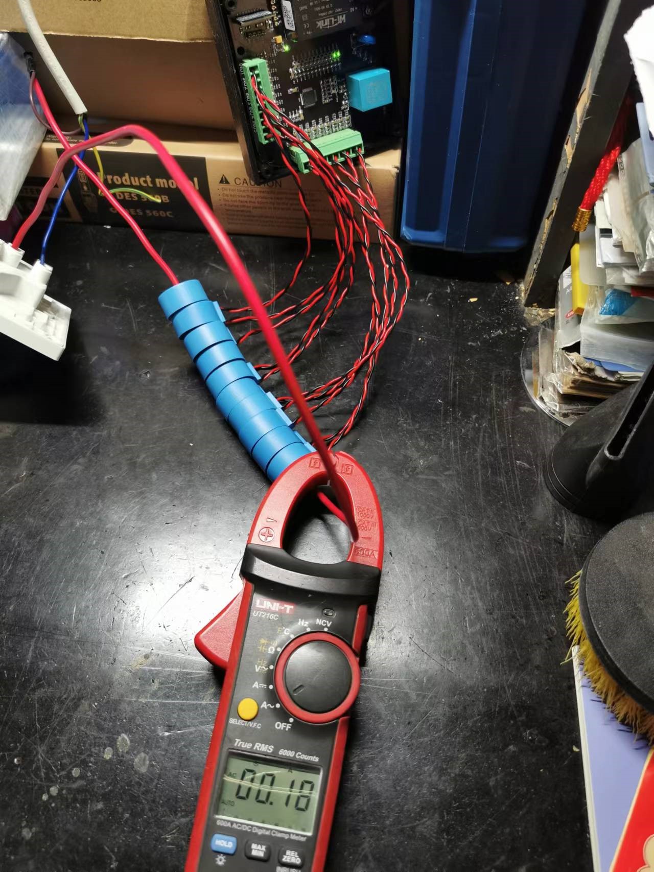
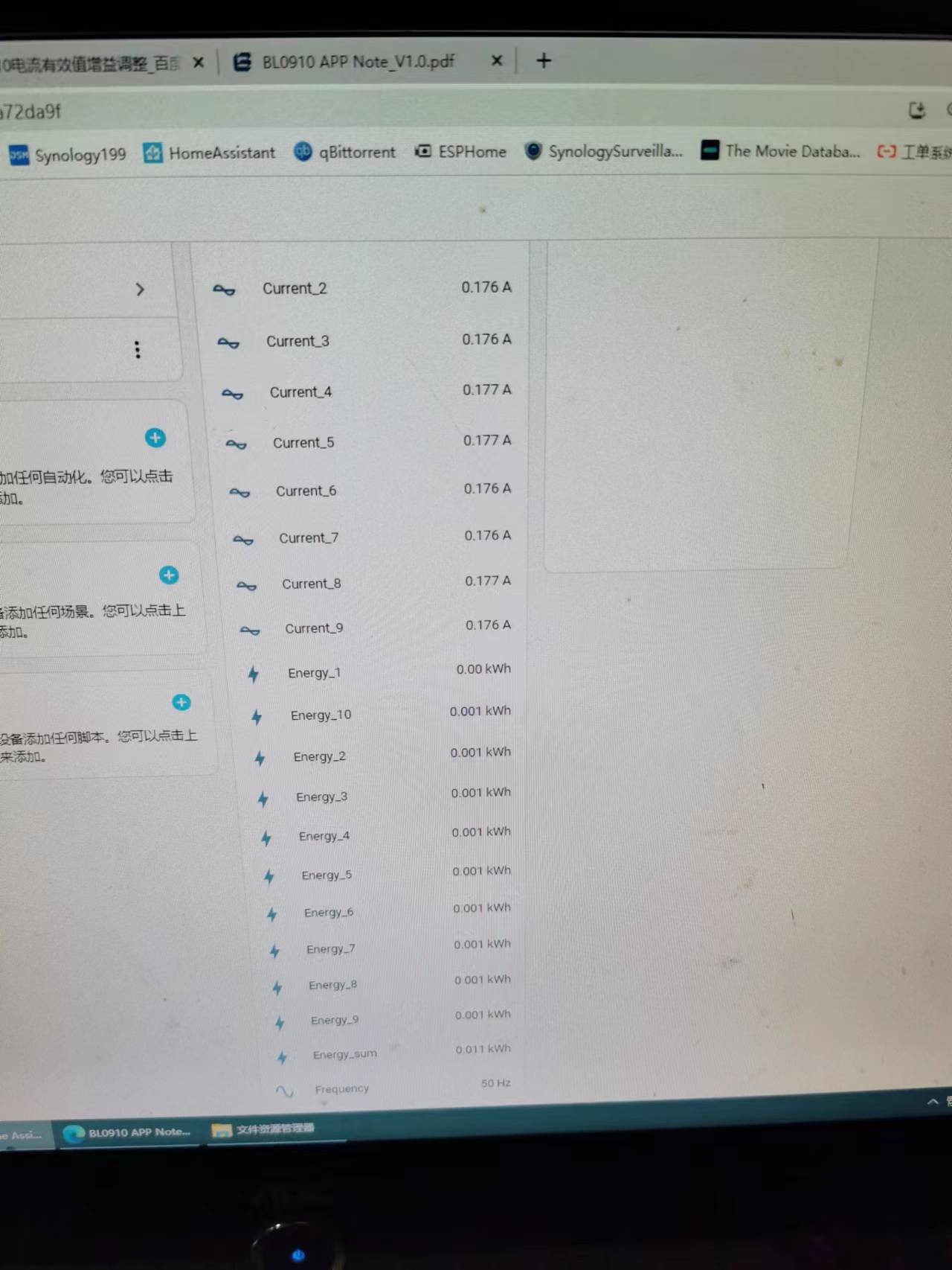
ESP8525 controls BL9010 to collect 10-channel power data.
It can be integrated with the HomeAsistant smart home platform to collect data from 10 energy meters, sharing one voltage channel and connecting it to 10 current channels to generate 10 energy meter readings.
This design is based on polisher's [Hardware DIY] "DIY ESPhome: Homemade Multi-Channel WiFi Power Meter for Beginners". The original hardware was for 6 channels. This design was adjusted and rearranged, with external components modified according to the Belling BL0910 PDF, and register parameters modified as described in the original. It was prototyped and successfully tested at JLCPCB to achieve 10-channel power acquisition. Components meet Belling's accuracy and parameter requirements. The WiFi chip used is the ESP8285. Status indicator lights and overcurrent indicator lights for each channel were added for easier monitoring of RXD and TXD transmission/reception. Other issues can be found in the original author's documentation.


BL0910.zip
EspHome.docx
PDF_ESP8525 Controlling BL9010 to Collect 10 Channels of Power Data.zip
Altium_ESP8525 controls BL9010 to collect 10-channel power data. (zip file)
PADS_ESP8525 controls BL9010 to collect 10-channel power data. (zip file)
BOM_ESP8525 controls BL9010 to collect 10-channel power data.xlsx
96017
electronic


 京公网安备 11010802033920号

 1200RGG1001B3GB


