100~240VAC to 12V 1A switching power supply module
PDF_Small Power Bare Board Power Supply.zip
Altium_low-power bare board power supply.zip
PADS_Small Power Bare Board Power Supply.zip
BOM_Small Power Bare Board Power Supply.xlsx
96009
[Minimum System Board] STC32G12K128 Core Board
Core board design based on STC32G12K128 microcontroller
The chip is STC32G12K128-Beta, and the board has an onboard CH340N, allowing direct program download via a Type-C data cable.
The board includes four LEDs, a 341 reference voltage, a 24C02 chip (IIC), and three buttons.
It is suitable for beginners.
PDF_【Minimum System Board】STC32G12K128 Core Board.zip
Altium_【Minimum System Board】STC32G12K128 Core Board.zip
PADS_【Minimum System Board】STC32G12K128 Core Board.zip
BOM_【Minimum System Board】STC32G12K128 Core Board.xlsx
96010
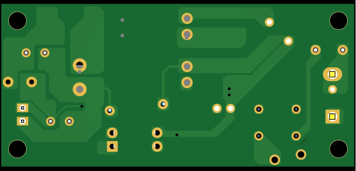
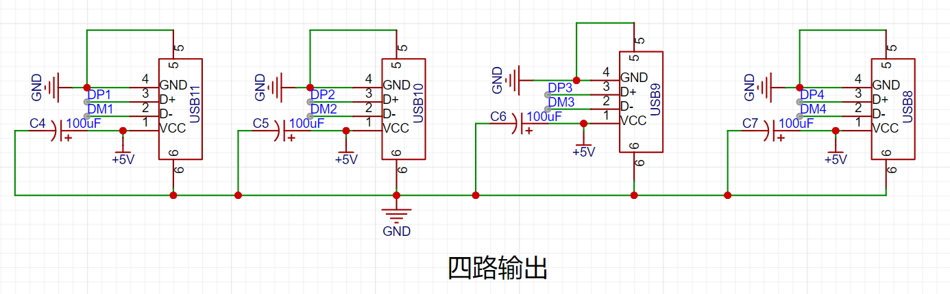
USB 2.0 expansion dock
No software debugging required, this simple and easy-to-use USB docking station with one input and four outputs is especially suitable for freshmen.
1. Chip circuit

2. Input circuit

3. Output circuit
Note: 1. When routing the USB data lines DM (D+) and DP (D-), differential pair routing is required.
2. The USB male connector pads should be positioned as close as possible to the edge of the board frame.
Gerber_PCB1_2023-11-27.zip
BOM_Block_PCB1_2023-11-27.xlsx
C192893_624110D24898D57AAC785E3DF98EA862.pdf
PDF_USB2.0 Dock.zip
Altium_USB2.0 Dock.zip
PADS_USB2.0 Dock.zip
BOM_USB2.0 Dock.xlsx
96011
STM32F103ZET6 Core Board Verification
STM32F103ZET6 core board
The STM32F103ZET6 core board features a download port and a serial port, using DAP-link for downloading.
It includes 3.3V and 5V power indicators, as well as two program running indicators.
The core board contains three buttons: a reset button, two function buttons, and EEPROM, FLASH, and SD card modules (not yet verified). Currently, program downloading works without issue.
The connection pins are the same as those on the Zhengdian Atomic Elite board.
PDF_STM32F103ZET6 Core Board Verification.zip
Altium_STM32F103ZET6 core board verification.zip
PADS_STM32F103ZET6 core board verification.zip
BOM_STM32F103ZET6 Core Board Verification.xlsx
96013
∞*∞ Dot matrix screen
A dot matrix screen composed of 1588as/bs dot matrix and 74hc595 cascaded components, which can be spliced together to form an infinitely large screen.
Features:
1. Uses 1588AS/BS dot matrix modules . 2.
Cascaded from 74HC595 modules.
3. Can be spliced together to an infinite size
. 4. Occupies only 3 I/O ports.
5. Optimized circuit design compared to the previous
generation. 6. Compatible with the
Arduino code provided by the previous generation module:
Uses the "ShiftRegister74HC595" third-party library, which needs to be downloaded from the library manager (old version test program, only supports 4 cascaded modules).
The new version code uses the official SPI library, and the test program supports at least 200 cascaded modules (using ESP8266; if using other libraries, it can support approximately 400 modules).
The new version code has poor readability; to understand the code principles, please download the old version.
Note:
Due to the cascading of 74HC595 modules, the scanning time is relatively long, so the maximum number of cascaded modules depends on the speed of the MCU used.
Connection method:
See the open-source project "16*16 dot matrix screen"
module configuration.
Effect: (Scrolling playback)

Dot matrix test.ino
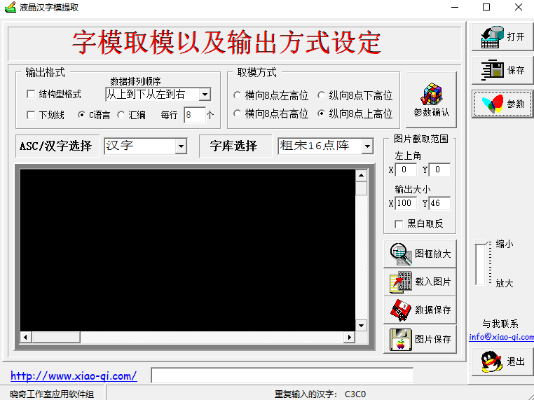
LcmZimoLCD font extraction tool software. (zip)
Dot matrix screen (new version).ino
PDF_∞_∞ Dot matrix screen.zip
Altium_∞_∞ dot matrix screen.zip
PADS_∞_∞ Dot Matrix Screen.zip
BOM_∞_∞ Dot Matrix Screen.xlsx
96014
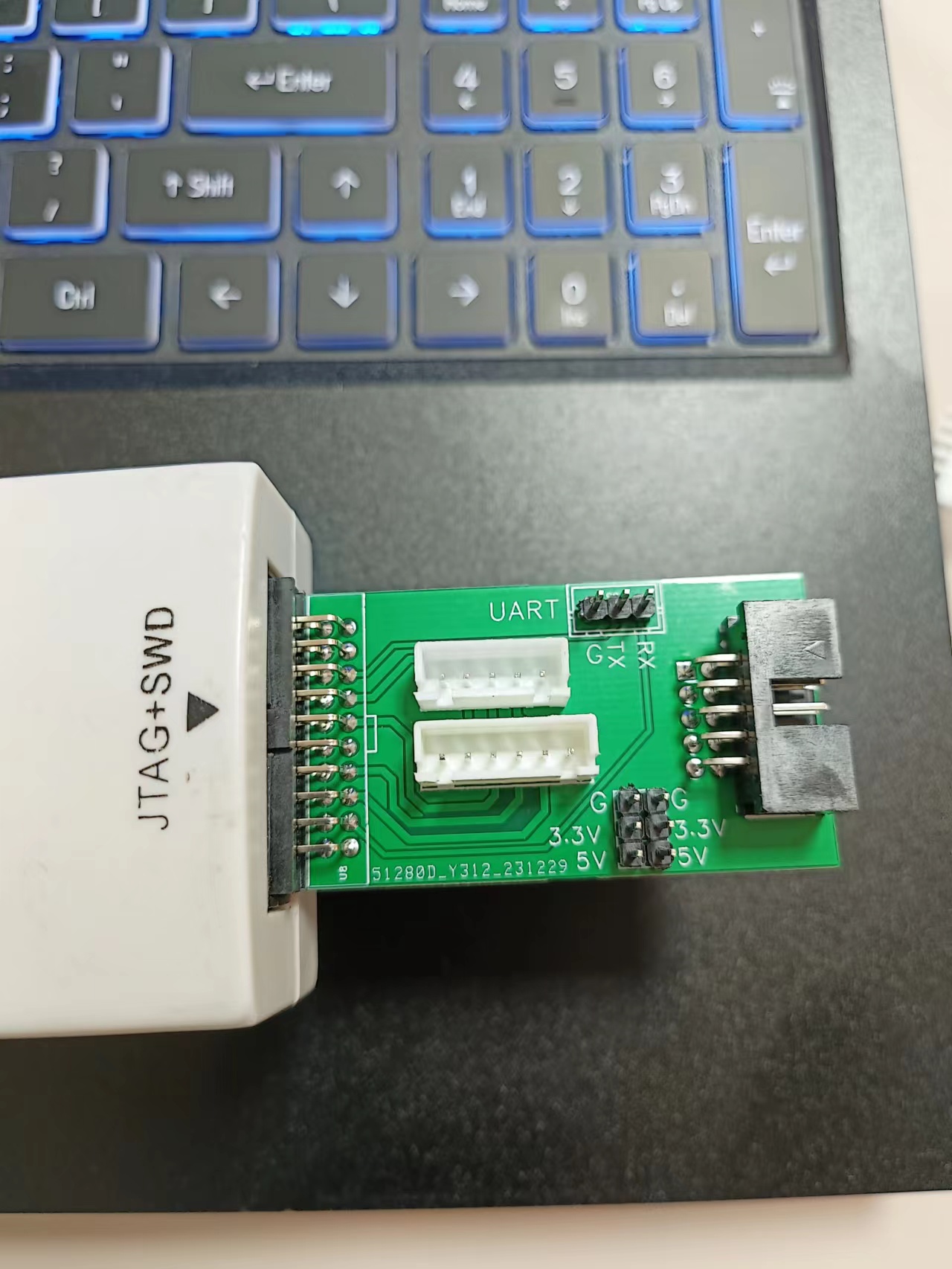
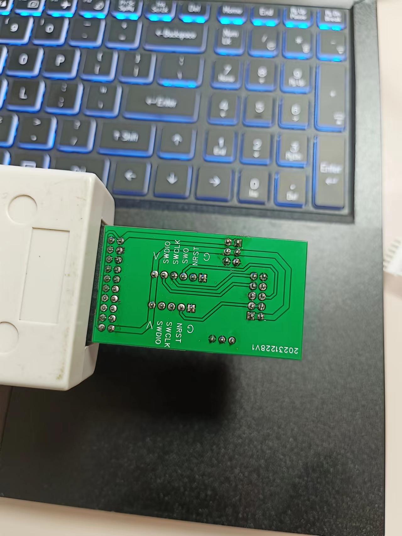
Homemade JLINK interface adapter board
The J-Link adapter board mainly features 5-pin, 6-pin, and 10-pin connectors. It also includes a UART and external power supply. It's relatively simple, but practical.
The J-Link adapter board mainly provides 5-pin, 6-pin, and 10-pin connectors. It also includes a UART and external power supply. It's relatively simple but practical.
One issue arose during testing: I initially intended to bring out the 5V output, but it turned out to be only 3.3V. Otherwise, there were no problems.

PDF_JLINK Interface Adapter Board (DIY) .zip
Custom-made Altium JLINK interface adapter board. (zip)
Homemade PADS_JLINK interface adapter board. (zip)
Homemade BOM_JLINK interface adapter board.xlsx
96016
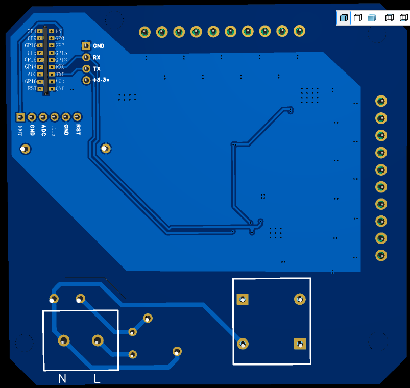
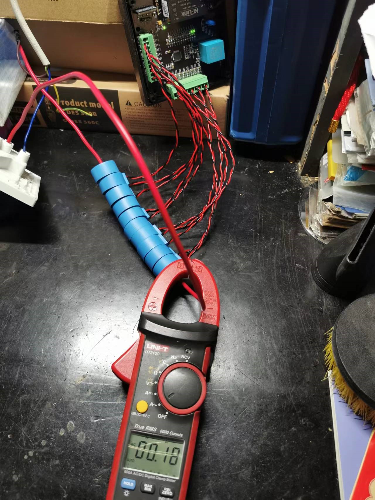
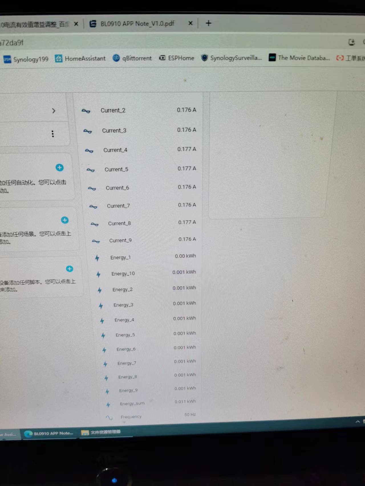
ESP8525 controls BL9010 to collect 10-channel power data.
It can be integrated with the HomeAsistant smart home platform to collect data from 10 energy meters, sharing one voltage channel and connecting it to 10 current channels to generate 10 energy meter readings.
This design is based on polisher's [Hardware DIY] "DIY ESPhome: Homemade Multi-Channel WiFi Power Meter for Beginners". The original hardware was for 6 channels. This design was adjusted and rearranged, with external components modified according to the Belling BL0910 PDF, and register parameters modified as described in the original. It was prototyped and successfully tested at JLCPCB to achieve 10-channel power acquisition. Components meet Belling's accuracy and parameter requirements. The WiFi chip used is the ESP8285. Status indicator lights and overcurrent indicator lights for each channel were added for easier monitoring of RXD and TXD transmission/reception. Other issues can be found in the original author's documentation.


BL0910.zip
EspHome.docx
PDF_ESP8525 Controlling BL9010 to Collect 10 Channels of Power Data.zip
Altium_ESP8525 controls BL9010 to collect 10-channel power data. (zip file)
PADS_ESP8525 controls BL9010 to collect 10-channel power data. (zip file)
BOM_ESP8525 controls BL9010 to collect 10-channel power data.xlsx
96017
electronic


 京公网安备 11010802033920号

 1N746C


