We use AA batteries in many situations, often using two 1.5V batteries. In situations where batteries are used extensively, the cost of battery consumption can be considerable.
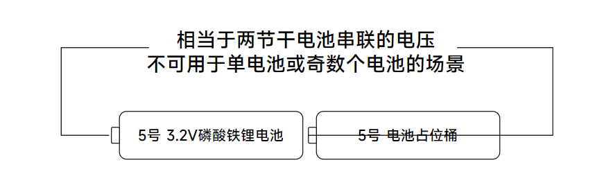
Years ago, lithium iron phosphate batteries existed. These are rechargeable, with each cell at 3.2V, equivalent to two regular AA batteries, and a higher discharge current than regular alkaline batteries.
However, the chargers that came with these batteries were 220V, which wasn't very convenient in practice, especially for outdoor use.
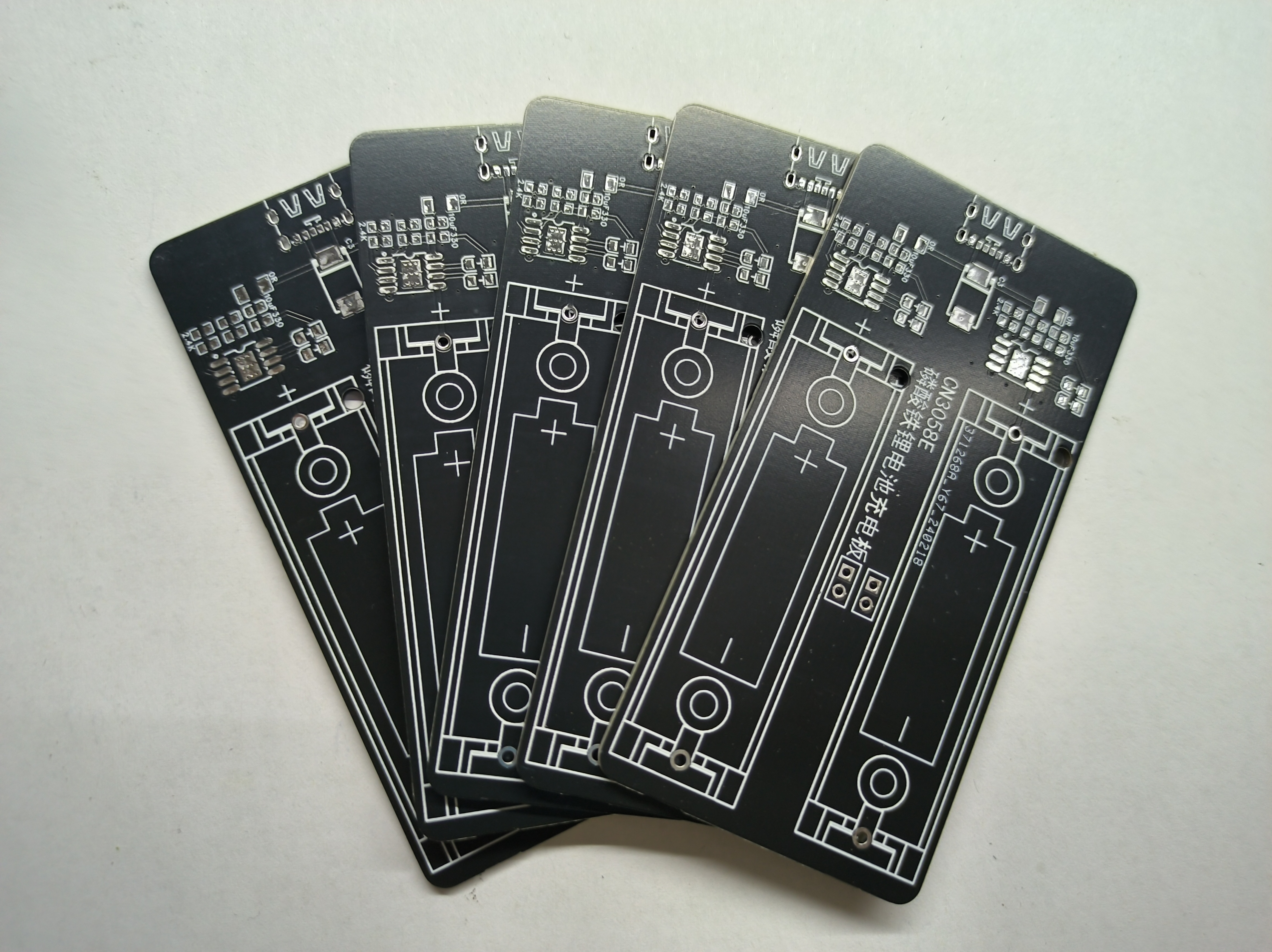
Analyzing the charger circuit, the charging chip used is CN3058E, with a supply voltage of 3.8V to 6V. This means it can be powered by a regular mobile phone charger, car charger, or power bank.
Therefore, this board was made to charge two lithium iron phosphate batteries separately, which should meet most outdoor needs.
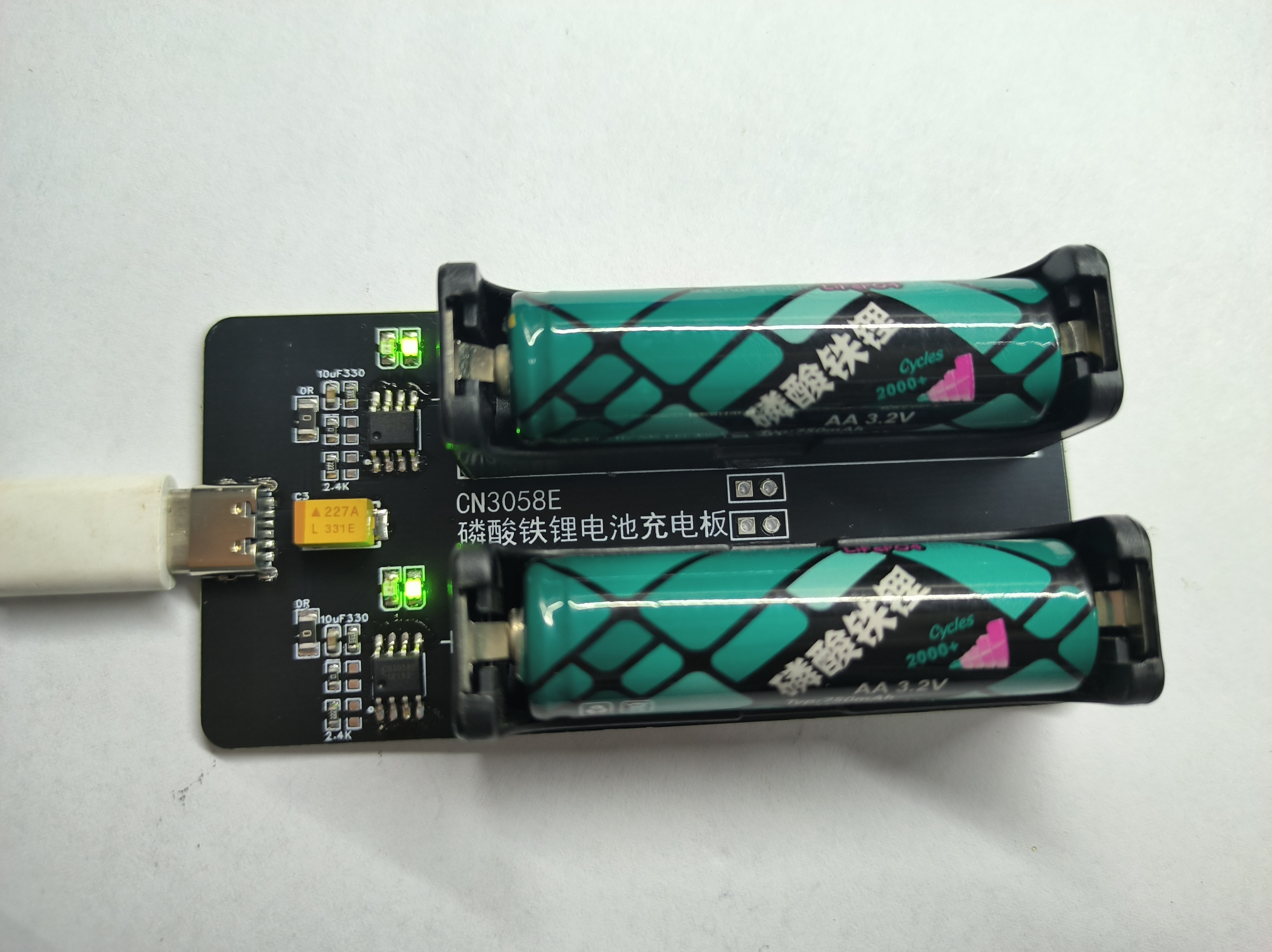
The two charging circuits are identical and independent. Either circuit can be used, or both can be used simultaneously.
Because a single lithium iron phosphate battery is 3.2V, when using two batteries, a dummy battery must be used in conjunction. Using two lithium iron phosphate batteries could potentially damage the device.
The red and green LEDs on the board are charging indicators; red indicates charging and green indicates charging is complete.
R3/R4 on the board controls the charging current. Resistors can be soldered as needed; two mounting points are provided to facilitate specific resistance values. The 2.4K resistor in the circuit diagram outputs a charging current of approximately 500mA.
The board has a pre-installed thermistor pad for monitoring battery temperature during charging. R1/R2 is used to set the temperature monitoring range. If R2 is soldered with a 0Ω resistor and the TEMP pin is grounded, the battery temperature monitoring function will be disabled.
I haven't made a casing for it because JLCPCB's circuit boards are of decent quality and strong enough for normal handling, and the black circuit board looks quite nice, so I opted for a bare circuit. However, I don't rule out adding a casing later.
Miniature standard PoE discrete module based on XS2100S and SY8502 chips. Suitable for smart home retrofitting.
Background:
I've been upgrading my smart home system recently.
Since there are excess network cables pre-installed on the ceiling, I considered mounting the gateways ceiling-mounted and powering them via PoE.
However, Xiaomi's central gateway and multi-mode gateway both use external adapters, and the PoE splitters on Taobao are bulky and unsightly.
Therefore, this project was created to build a PoE power module installed inside the gateways.
I measured the power consumption of the central gateway and multi-mode gateways and found that the central gateway's maximum power is no more than 5W (12V), and the multi-mode gateway's is less than 3W (5V).
Therefore, the AF standard is sufficient for PoE.
Design:
The design power only needs to meet 5W for continuous operation. Considering the module needs to be integrated into the network management system, a non-isolated DC-DC solution was chosen.
1. Choose a chip that integrates PD and buck controller, such as the Si3406. 2. Choose an
independent PD chip + high-voltage buck chip.
Previously, I tested the Si3406 non-isolated solution, which had a relatively high temperature rise. Therefore, I prioritized an independent PD chip + high-voltage buck
chip. Selection:
1. There are many PD chip options. The most commonly used are the TPS2378 and XS2100S. For cost considerations, the 2100S was chosen.
2. Choosing a high-voltage buck chip is more challenging. Considering voltage withstand, size, and temperature rise, I searched for a long time before finally choosing the SY8502. Although it's not small, its performance is quite good.
Debugging and Testing
(To be supplemented

) Gateway Modification:
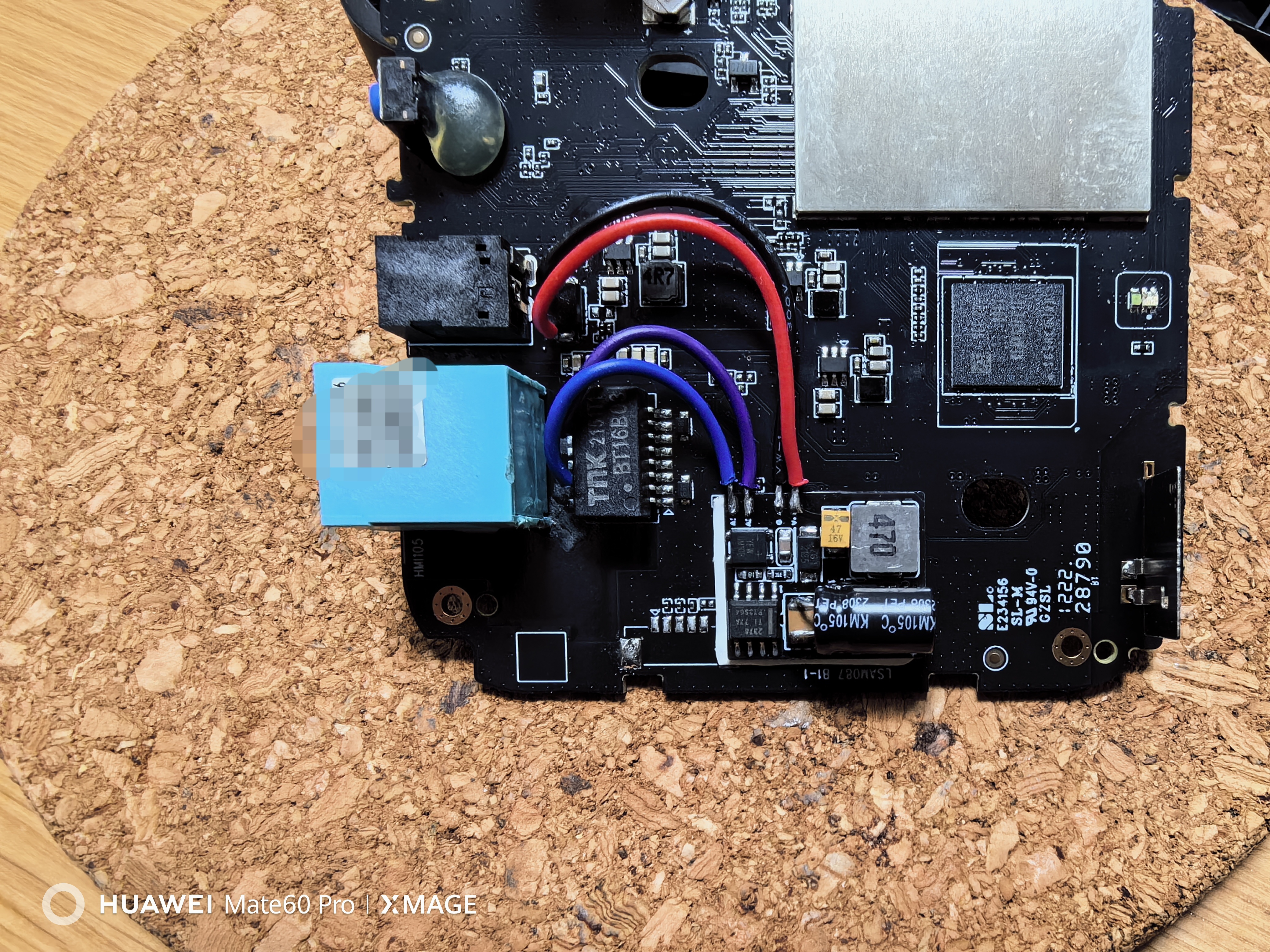
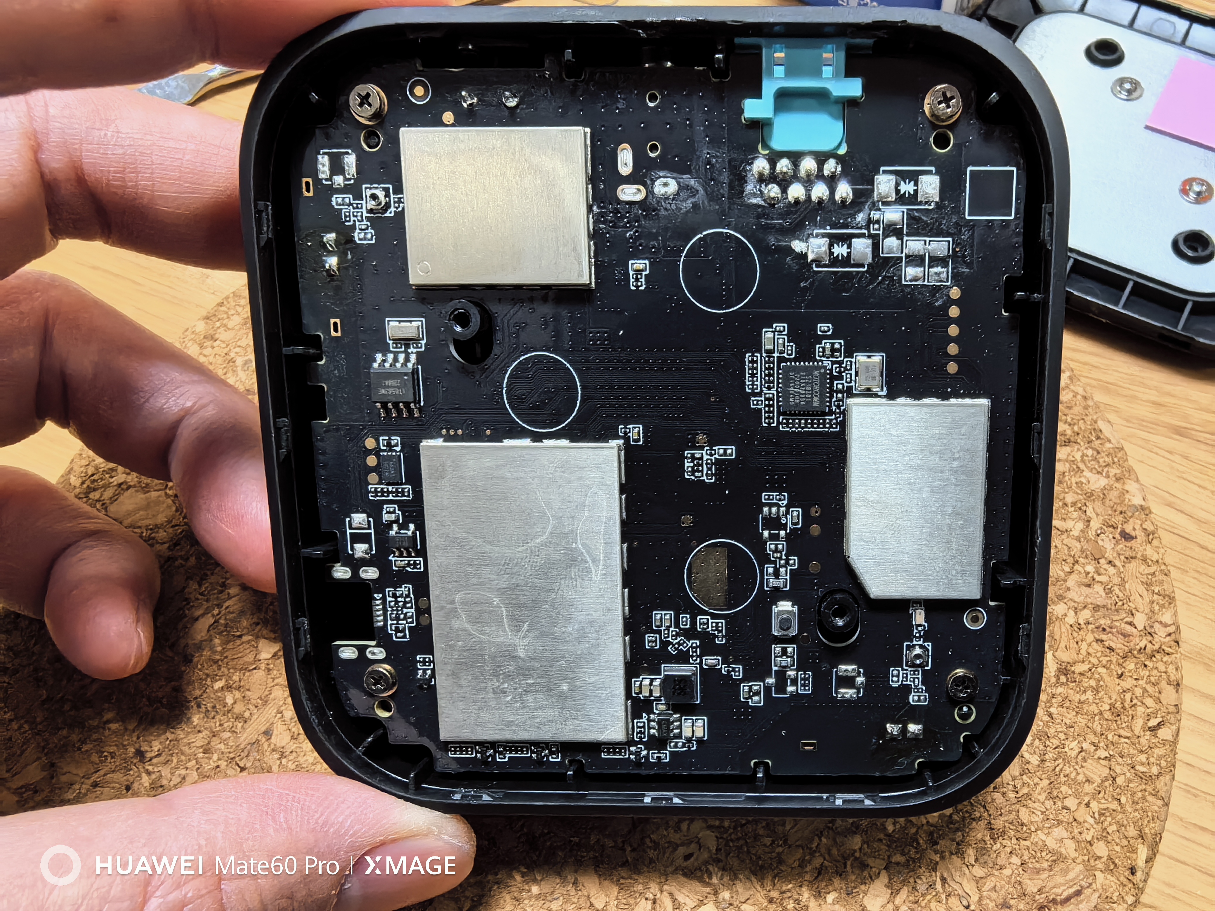
1. After disassembling the gateway, locate the center tap of the network transformer.
2. Measure the two center taps (1, 2, 3, 6). If they are connected, they need to be isolated from the PCB.
3. Remove the Bobsmith circuit
. 4. Connect the center tap to A1 and A2 of the module, regardless of polarity.
5. Locate the gateway power supply circuit, find the large input capacitor, and connect it directly to the module's G and V+. Pay close attention to the polarity here; do not get it wrong.
6. Apply thermally conductive double-sided tape to the back of the module, find an empty slot on the motherboard (near the power supply), and attach it directly to the motherboard for heat dissipation.
7. Directly plug it into the PoE switch and power it on for testing.
PDF_Mini PoE Detachment Module.zip
Altium_Mini PoE Detachable Module.zip
PADS_Mini PoE Detachable Module.zip
BOM_Mini PoE Decoupling Module.xlsx
96021
OCV_TESTER
STM32 Current and Voltage Tester
The STM32 current and voltage tester
uses the INA226 to test the voltage and current values of a USB line
and displays the test parameters on an OLED screen.
PDF_OCV_TESTER.zip
Altium_OCV_TESTER.zip
PADS_OCV_TESTER.zip
BOM_OCV_TESTER.xlsx
96022
RP2040 MINI
(30*16mm) Small board RP2040 microcontroller
This is a summary of
the RP2040 small PCB, 30mm * 16mm (USB-C protrudes approximately 2mm), which runs normally and costs less than 15 RMB. The voltage regulator is an RT9013-33GB, with a maximum current of 500mA. A total of 12 GPIO
pins
are brought out to half-holes, including 4 GPIOs that can function as an ADC. All other I/O pins are brought out to the back of the PCB. The pins on the front are labeled with their commonly used functions for my own convenience. (Image attached: 3V3
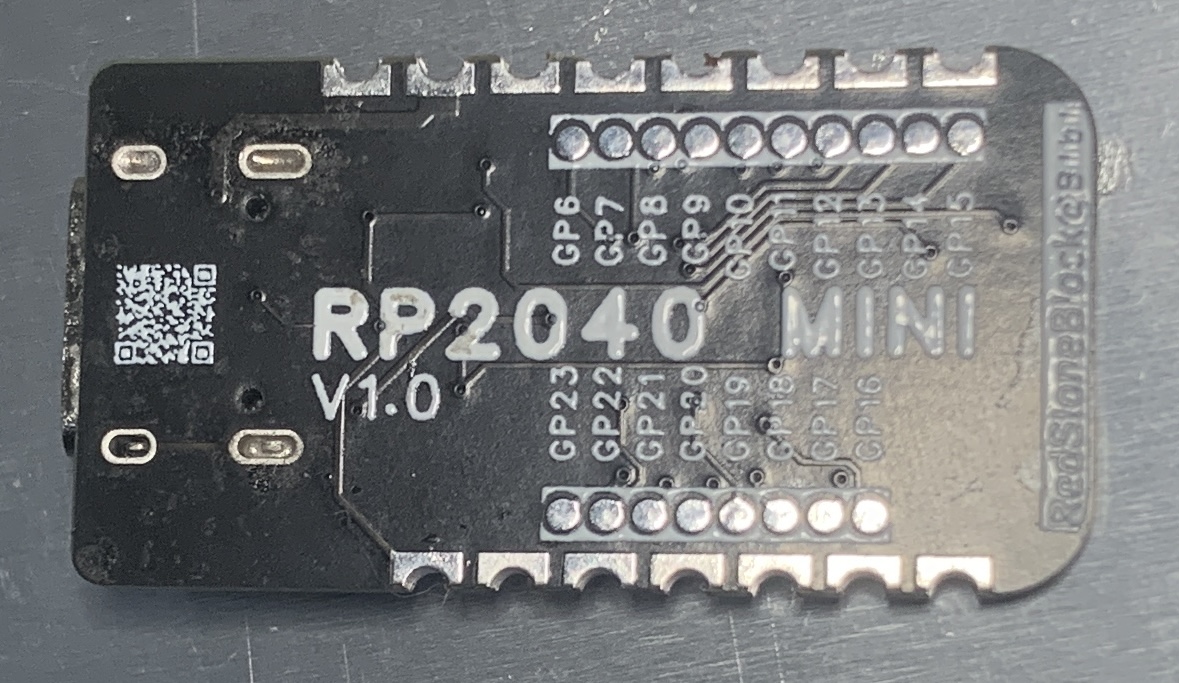
test shows 3.25V, Blink test is normal.) Note that my PCB uses 0201 packages. I'm about to take my high school entrance exam. If I release version V1.1, I will change all surface-mount capacitors and resistors to 0402 packages. CC BY-NC-SA 4.0 Creative Commons Attribution-NonCommercial-ShareAlike License. Commercial use is prohibited. Copying, modifying, and sharing are allowed, but attribution is required. Personal use is free . © 2023-2024 Song Yuanzhuo, All rights reserved.

685dbcb45aee5a60f6b0cf463dc4349c_raw.mp4
PDF_RP2040 MINI.zip
Altium_RP2040 MINI.zip
PADS_RP2040 MINI.zip
BOM_RP2040 MINI.xlsx
96023
Redmi 2 power supply board
The Redmi 2's direct power supply board has two DC-DC step-down converters, a wide voltage input of 4-36V, and a single-channel maximum current support of 5V 3A. It also has a hub function, allowing for a 1-to-4 splitter configuration. Currently, it has been tested and is stable and usable.
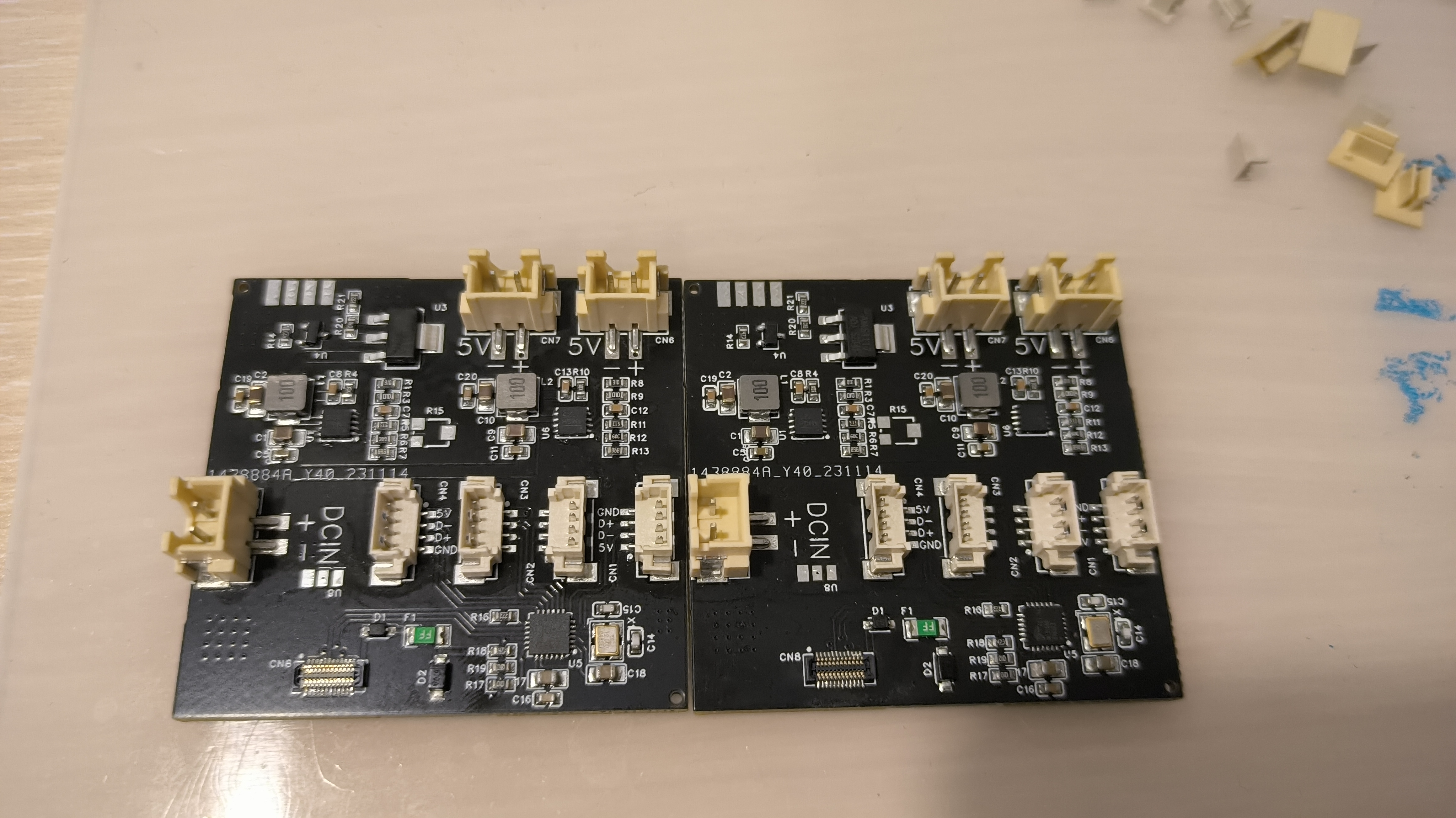


This is a dual-channel DC-DC step-down circuit, with one XH2.54 terminal as input and two XH2.54 terminals as output. A separate step-down chip is used for powering the mobile phone. The FE1.1S USB hub chip uses an MX1.25 4P terminal as an expansion interface.
This version is obsolete; those interested can check out version V2 on my homepage.
PDF_Redmi 2 Power Supply Board.zip
Altium_Redmi2 power supply board.zip
PADS_Redmi 2 Power Supply Board.zip
BOM_Redmi 2 Power Supply Board.xlsx
96024
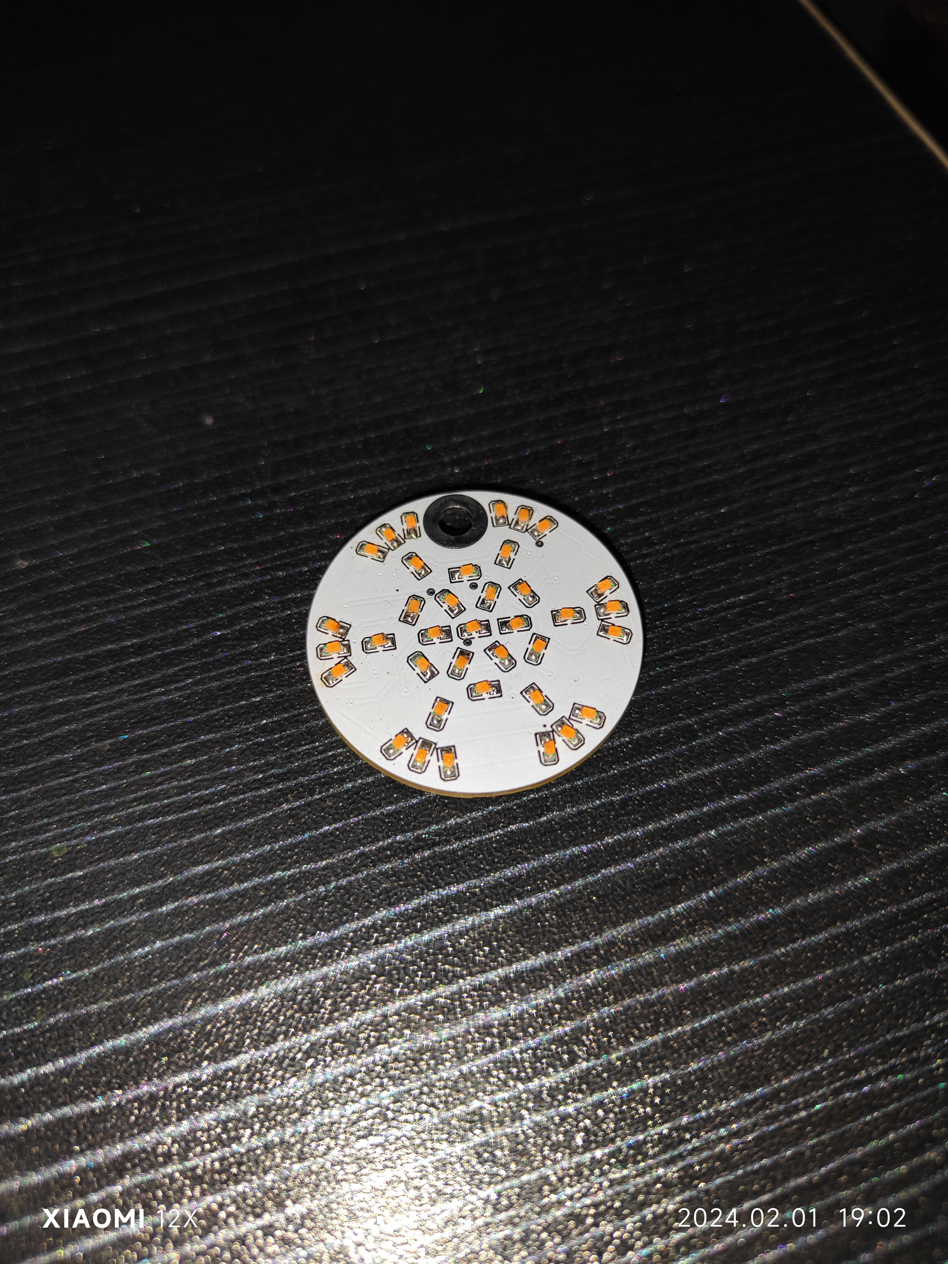
Snowflake lamp
The touch-sensitive snowflake light's design and main control scheme are inspired by the snowflake magnetic control light project from Bilibili up-master @黑果工作室.
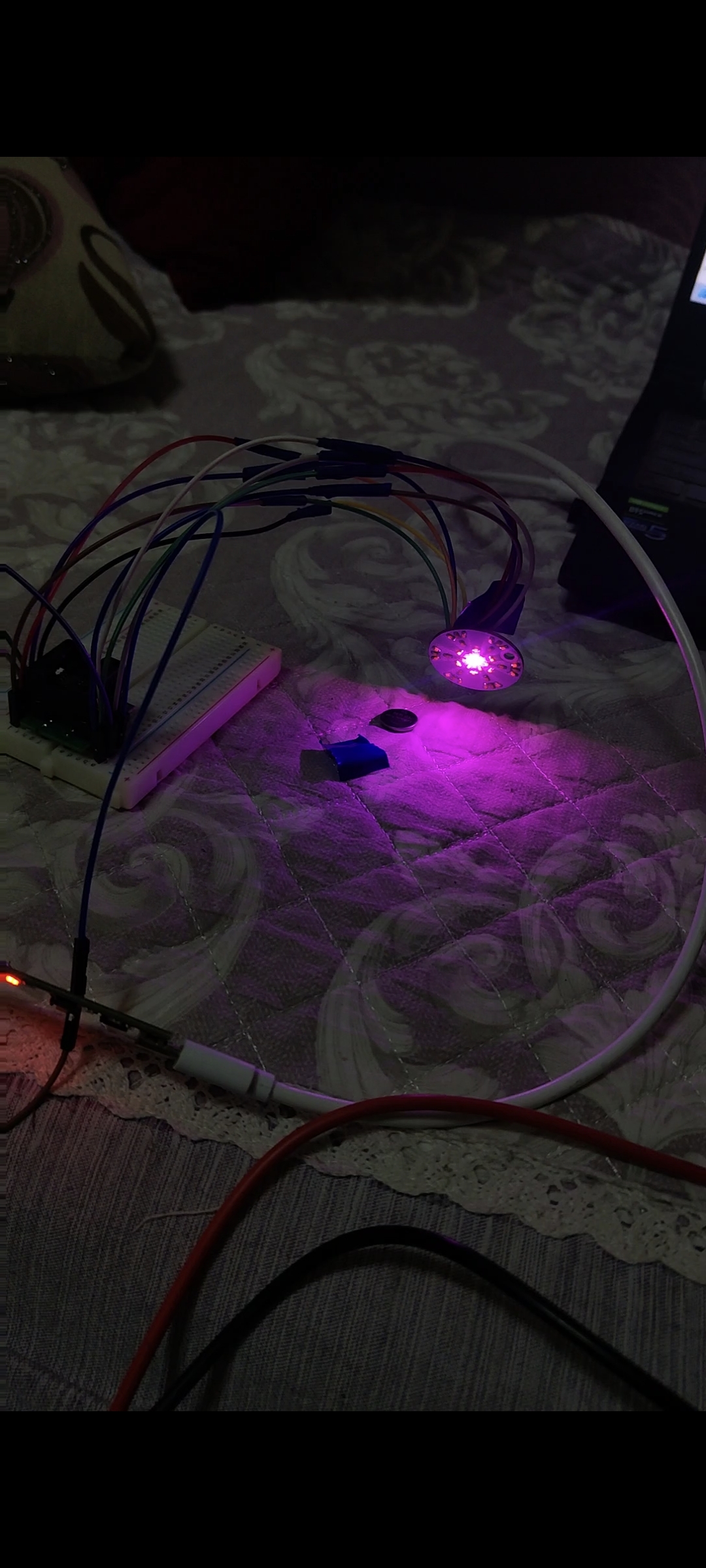
The Snowflake Light (Touch Control)
is an original open-source project. I modified the original main control scheme to be touch-sensitive, eliminating the need for a separate magnet. Demonstration and usage tutorials can be found in the Bilibili video.
Demonstration video: https://www.bilibili.com/video/BV1xt421H7NA/?share_source=copy_web&vd_source=97b5c47ade0bdf9975035b71336bdd0a
Source code: https://gitee.com/hw_ovo/snow-light_-stc8
I. Chip Selection
: Main Control: STC8G1K08A (STC8G1K08 is also acceptable; the difference is that the one with the "A" has a PWM output mode, but the impact is minimal because three PWM pins are insufficient; you still need to implement 5-pin PWM using a timer). This chip is sufficient and does not require external circuitry such as a crystal oscillator, greatly reducing PCB layout space and subsequent soldering time. Its performance is adequate for this project.

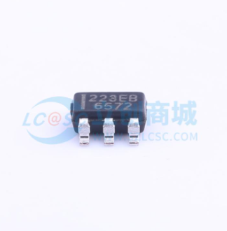
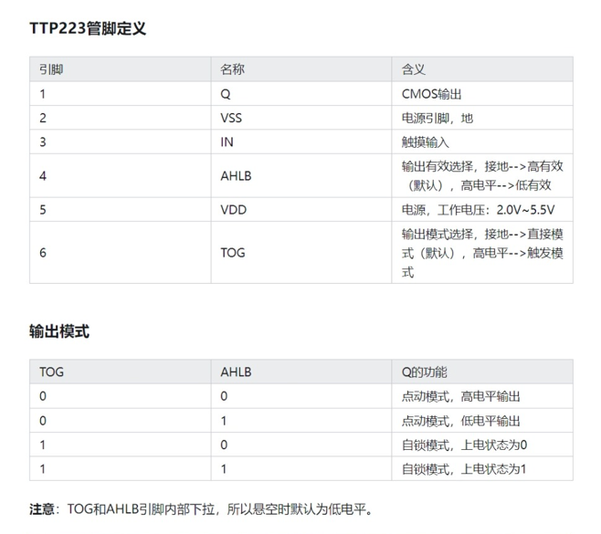
Touch chip: TTP223. When both the AHLB and TOG pins are connected to a high level, the OUT output is high when the finger is not touching the IN pin (i.e., the metal area being touched). However, when the IN pin is touched, the OUT output is low. This characteristic can be used to detect whether a finger is pressed by capturing the falling edge.
TTP223 schematic:
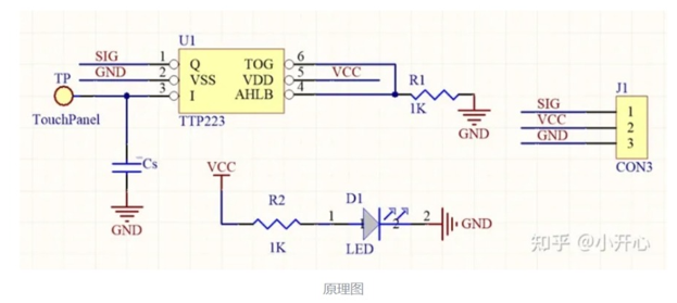
It's worth noting that the size of the Cs capacitor can adjust the sensitivity. Because I wanted to simplify the circuit and didn't have a pF-level capacitor, I grounded it directly, resulting in the highest sensitivity.
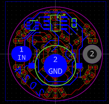
The schematic design
of the circuit is relatively simple. It has five LEDs from the inside out. Pins P31, P32, P33, P54, and P55 of the STC8G1K08A are used for PWM control of the LEDs. When the pin is high, the LED is off; when it is low, the LED is on. Pin P30 is set as a falling edge interrupt to capture the falling edge of the TTP223 output when a finger touches the circuit.
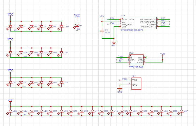
I didn't use a current-limiting resistor here, partly because I felt it made the circuit a bit dim during the verification phase, and partly because it's brighter without a resistor when using battery power, and it also reduces the number of components.
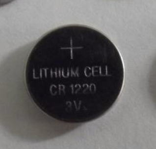
For the battery, I chose a CR1220 because I didn't want it to be too thick or too large. The battery base is also relatively small and thin, and it's a surface-mount device; the only downside is that I had to design the package myself. The overall
PCB
schematic design isn't difficult. Just pay attention to the layout and wiring, and leave a metal touch area, which can be replaced with a solder pad.
I created a large, multi-layered pad on the right side of the PCB to allow the finished product to be threaded through a rope as a small pendant. This pad can be removed if the pendant is not needed.
The source code documentation
uses Keil 4, not Keil 5. Theoretically, development with Keil 5C51 is similar, the development approach is the same, but some modifications might be needed; please search online for more information.
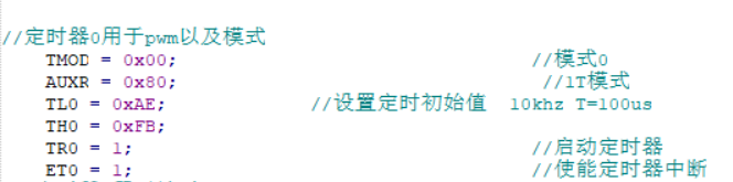
The STC8G1K08A only has 3 PWM pins, which is definitely insufficient, so a timer is needed for custom PWM control.
My PWM approach is as follows: First, set the timer to 10kHz, with a clock period of 100µs, denoted as t. Controlling the LED's on/off state by a small number of t's within 100 clock cycles (10ms, denoted as T) achieves different duty cycles for PWM output.
For example, assuming LED1 is lit for 10 small t's within one T, then LED1's duty cycle is 10%.
Of course, this approach may have drawbacks, such as potentially high power consumption, which can be optimized.
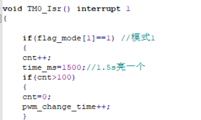
The main operating logic is as follows: after power-on initialization, the run_flag flag is set to one, and the program runs normally. When a finger is pressed, an interrupt is triggered, and after a certain period of time (500ms), the mode value is incremented by one. The mode value determines the snowflake light mode:
mode=1: gradual change, the LEDs light up sequentially from the inside to the outside, and then turn off sequentially from the outside to the inside;
mode=2: global breathing, all LEDs go from on to off and then on again;
mode=3: strobe, the LEDs flash on and off at a very fast frequency. I found it too flashy and dazzling, so I lowered the brightness. You can increase it according to your needs;
mode=4: constant on, as the name suggests, all LEDs are always on.
mode=5: Enters power-saving mode, all LEDs are off, and the clock stops
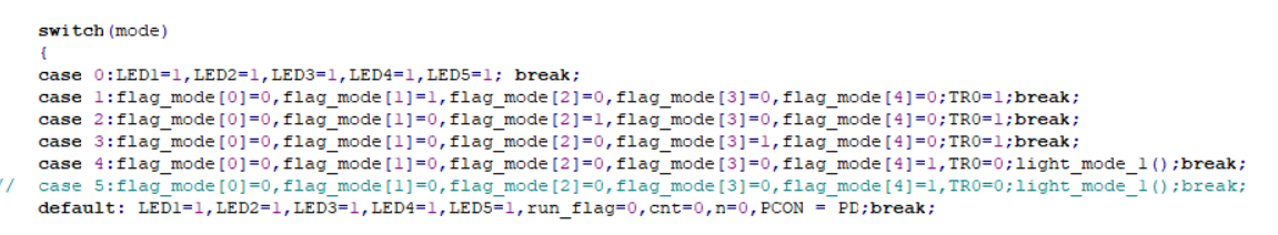
. To detect if a finger is pressed via an interrupt, P3.0 needs to be set to falling-edge interrupt (this pin interrupt can only be triggered by the falling edge). During normal operation, the run_flag bit is 1, and it increments by 1 with each press of mode. When mode is 5, power-saving mode is entered, and the run_flag bit is set to zero. When the finger is pressed again, it needs to be held for 2.5 seconds to restart normal operation. Theoretically, restarting should be done by combining it with another idle timer 1, but I haven't worked with these things for more than half a year, and I'm not particularly familiar with 51 microcontrollers and register-based programming, so I used this delay function method for detection.

The code for modes one to three is placed in the interrupt function of timer 0. The duration of each mode can be changed by modifying time_ms.
There are also some custom functions, which are relatively simple and can be modified and encapsulated as needed.
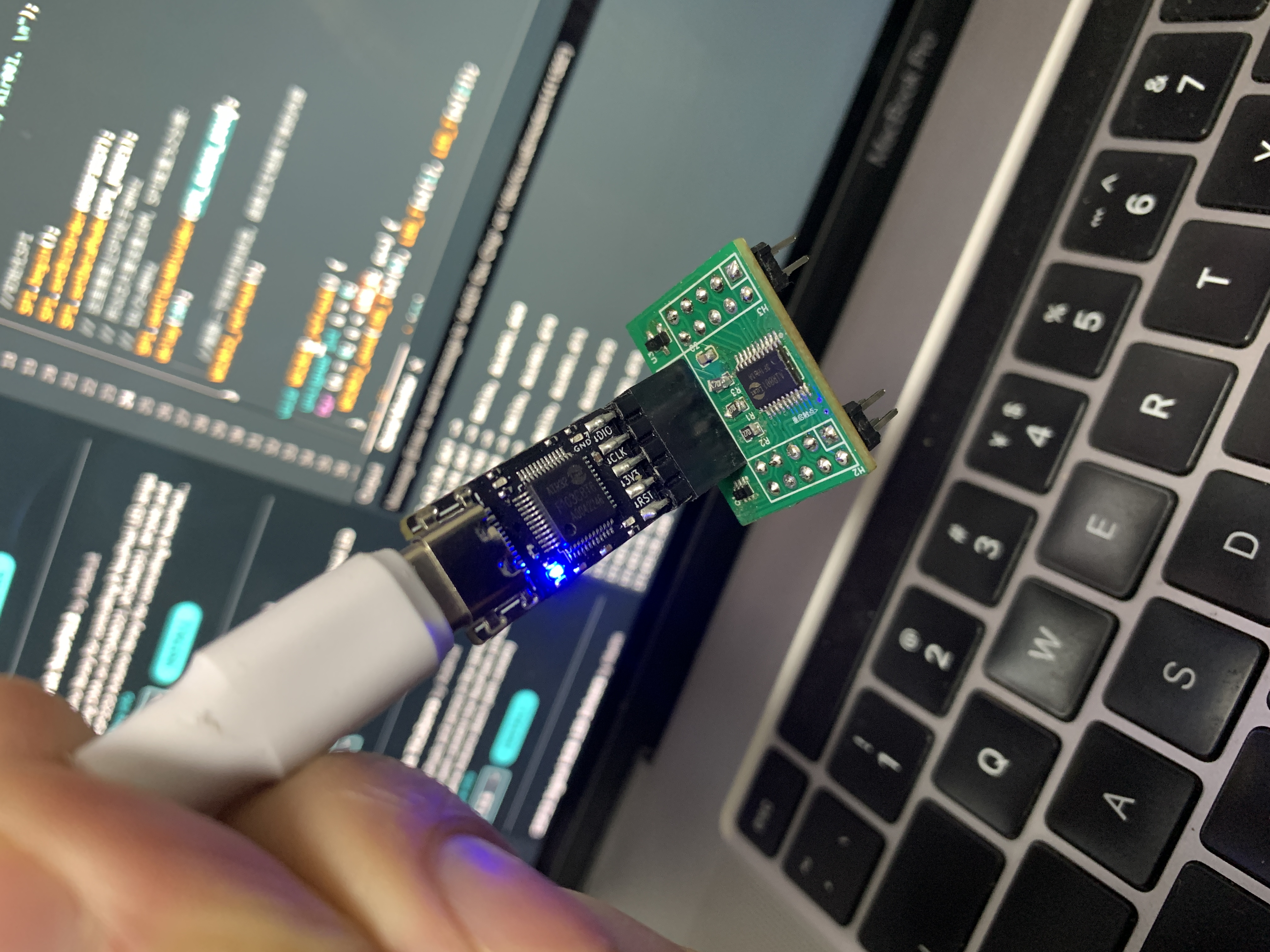
Programming instructions:
Programming is done via serial port using stc-isp-v6.92C (other versions are also acceptable).
Since I designed a verification board first and verified that the schematic and source code were correct before designing the final snowflake LED version, I didn't leave any programming ports in the PCB design for the sake of aesthetics.
Therefore, I needed to use wires to bring out the pins of the pads and then use an SOP8 programmer for programming. See the image below: [
Image of SOP8 programmer (note: select "narrow body" when purchasing)]
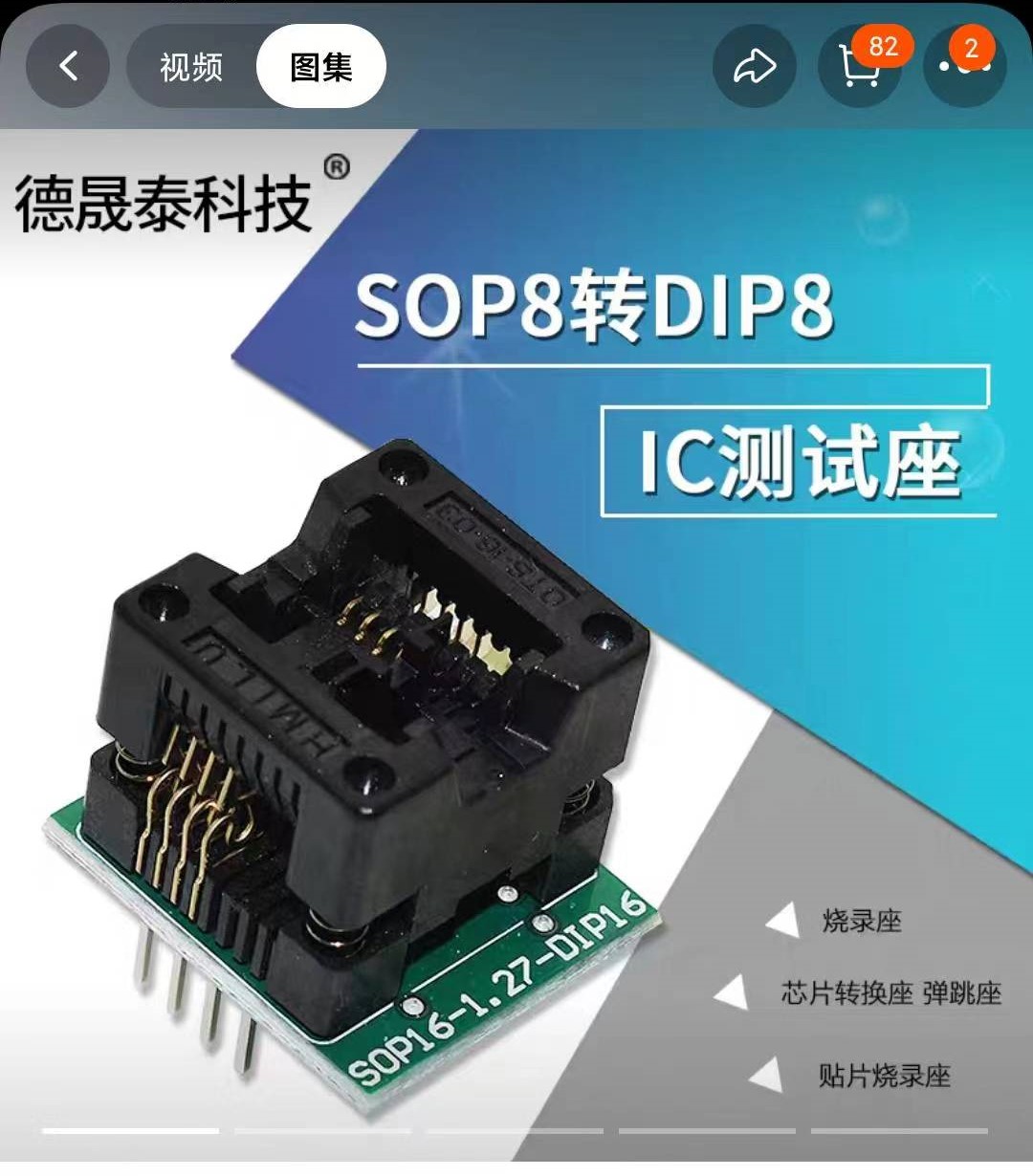
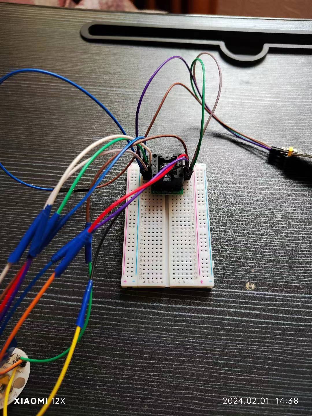
. (You only need to connect the programmer socket with a PCB jumper wire, and then program the chip via serial port. After all chips are programmed, you can solder them.)
Honestly
, I personally prefer the New Year's red color scheme; maybe I've just seen too much white lately and am aesthetically fatigued. I will upload
the other
source code to the Gitee platform and in the attachments; feel free to download it if needed.
Why isn't the PCB showing up? (Annoying~_~)
touch_snowlight.zip
VID_20240201_143927.mp4
PDF_SnowflakeLantern.zip
Altium_snowflake.zip
PADS_SnowflakeLamp.zip
BOM_SnowflakeLamp.xlsx
96025
Hezhou Air001 Single-sided Double-layer Mini Board
The very small, single-sided, double-layer air001 development board with automatic downloading capability, supports only 3.3V power supply.
This is the first development board design that aligns with the research and development of integrated circuits. It would be a shame to waste so many Air001 chips I have on hand. This is the smallest MINI single-sided, double-layer development board with automatic download, designed for modular embedding. It's used to research a module within a motorcycle infotainment system and has already been verified. Here's a simple demo video showing the WS2812 lighting up.
IMG_4157.MOV
PDF_Hezhou Air001 Single-sided Double-layer Mini Board.zip
Altium_合宙Air001 Single-sided Double-layer Mini Board.zip
PADS_HezhouAir001 Single-sided Double-layer Mini Board.zip
BOM_HezhouAir001 Single-sided Double-layer Mini Board.xlsx
96026
MP2225GJ-Z Power Management Module
This module, based on the MP2225GJ-Z chip, converts 3.3V and 5V outputs. It uses two MP2225GJ-Z chips, supports a maximum current output of 5A (datasheet), and has an 18V input. The module design is small and compact.
There will be a 0.3V voltage drop when using a 5V input, resulting in 3.0V and 4.7V outputs.
Note: When using a Type-C input, do not use a 12V (DC plug or terminal) input, as the inputs share the same circuit.
Power.mp4
PDF_MP2225GJ-Z Power Management Module.zip
Altium_MP2225GJ-Z Power Management Module.zip
PADS_MP2225GJ-Z Power Management Module.zip
BOM_MP2225GJ-Z Power Management Module.xlsx
96029
TinyVision V851se Heterogeneous AI Vision Network Development Kit
A heterogeneous AI vision network development kit based on V851se, with a 0.5TOPS NPU.
Heterogeneous AI Vision Network Development Kit based on V851se, 0.5TOPs NPU, supports RTSP

TinyVision. Purchase link:
https://item.taobao.com/item.htm?&id=756255119524
Accessory purchase links:
GC2053 Camera: https://item.taobao.com/item.htm?&id=736796459015
RJ45 100Mbps Cable (4P to RJ45 50CM): https://item.taobao.com/item.htm?&id=626832235333
PDF_TinyVision V851se Heterogeneous AI Vision Network Development Kit.zip
Altium_TinyVision V851se Heterogeneous AI Vision Network Development Kit.zip
PADS_TinyVision V851se Heterogeneous AI Vision Network Development Kit.zip
BOM_TinyVision V851se Heterogeneous AI Vision Network Development Kit.xlsx
96030
Simp keychain
Design a simp pendant to remind simps to drink more hot water, etc., to improve their efficiency. May every simp have a home.
Project Description:
With social development, technological progress, economic development, and economic expansion, the rapid advancement of modern electronic, communication, and computer technologies has led to an increase in the phenomenon of "sycophants" (or "sycophants"). This reflects a decline in trust and amplified loneliness in society, a natural human reaction for survival. This project combines embedded technology with the concept of "sycophancy" to design a "sycophant pendant" that reminds users to drink more hot water, etc., to improve the efficiency of sycophancy and provide a home for every sycophant.
Open Source License:
GPL 3.0.
Project Functionality: The project
will remind others to drink more hot water based on different temperatures and humidity levels.
Project Attributes:
This is the first public release of this project, and it is my original work. This project has not won any awards in other competitions.
Project Progress:
2024-01-01: PCB design completed, but not yet tested on a board.
2024-02-01: Soldering and debugging. The hardware
design
aims to be portable. First, it needs a battery, using a TP4056 for charging and a DC-DC chip for voltage regulation to power the ESP8266. It includes 2-3 buttons for changing cities, as many devices don't support this feature.
The software
uses the ESP8266 as the control core and is written in Python. First, the Python firmware is flashed, then the ESP8266 is developed using Python. It connects to a personal hotspot, retrieves weather information, and reminds users to drink more water based on temperature and humidity levels. The first two photos
show
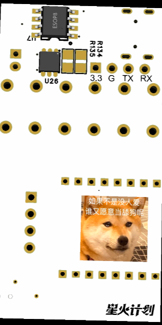

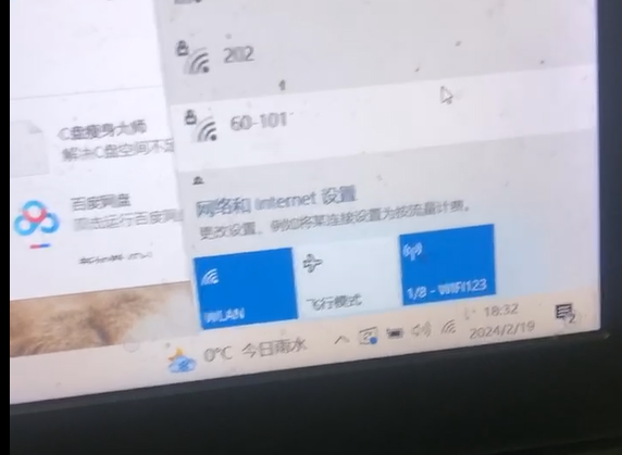
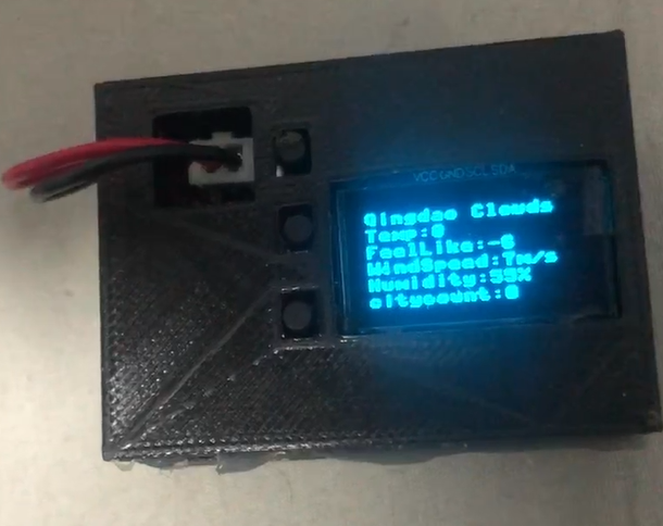
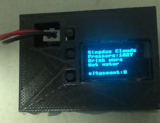

a 3D view of the PCB and a picture of the PCB soldering. The third photo shows the device connected to the personal hotspot after flashing the first firmware. The fourth and fifth photos show the screen displaying weather, wind direction, and reminders to drink water after flashing the second firmware and connecting to Wi-Fi. Pressing the two bottom buttons changes the city; the number of cities increases or decreases, and the information is updated when the first page is refreshed. Pressing the first button resets the settings.
Design Considerations:
First, you need to flash the Python firmware onto the ESP8266. Then, use uPyCraft.exe to open the two files and flash one of the firmware files first. Set your personal hotspot or other Wi-Fi network to the username "WIFI123" and password "12345678". The device will then connect to your Wi-Fi. Next, flash the second firmware. After a short while, the screen will refresh.
Other
C111F83CB7CB16997F109CA29C22A9C6.mp4
Part 1.stl
1537.stl
esp8266-20220117-v1.18.bin
tiangouoledxianshuazhege.py
tiangouoled.py
PDF_Simp Accessory.zip
Altium_licker accessory.zip
PADS_Simp Keychain.zip
BOM_Simp Accessory.xlsx
96031
electronic
 However, the chargers that came with these batteries were 220V, which wasn't very convenient in practice, especially for outdoor use.
 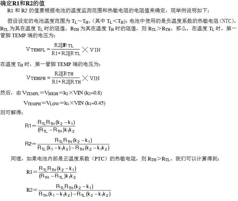 I haven't made a casing for it because JLCPCB's circuit boards are of decent quality and strong enough for normal handling, and the black circuit board looks quite nice, so I opted for a bare circuit. However, I don't rule out adding a casing later.


 京公网安备 11010802033920号

 RNS1CCT26A1001B


