The Snowflake Light (Touch Control)
is an original open-source project. I modified the original main control scheme to be touch-sensitive, eliminating the need for a separate magnet. Demonstration and usage tutorials can be found in the Bilibili video.
Demonstration video: https://www.bilibili.com/video/BV1xt421H7NA/?share_source=copy_web&vd_source=97b5c47ade0bdf9975035b71336bdd0a
Source code: https://gitee.com/hw_ovo/snow-light_-stc8
I. Chip Selection
: Main Control: STC8G1K08A (STC8G1K08 is also acceptable; the difference is that the one with the "A" has a PWM output mode, but the impact is minimal because three PWM pins are insufficient; you still need to implement 5-pin PWM using a timer). This chip is sufficient and does not require external circuitry such as a crystal oscillator, greatly reducing PCB layout space and subsequent soldering time. Its performance is adequate for this project.

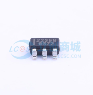
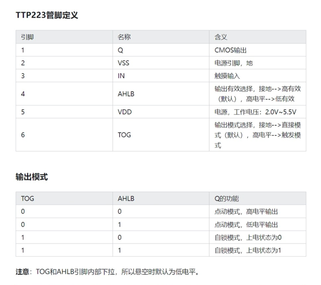
Touch chip: TTP223. When both the AHLB and TOG pins are connected to a high level, the OUT output is high when the finger is not touching the IN pin (i.e., the metal area being touched). However, when the IN pin is touched, the OUT output is low. This characteristic can be used to detect whether a finger is pressed by capturing the falling edge.
TTP223 schematic:
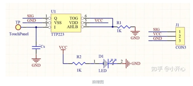
It's worth noting that the size of the Cs capacitor can adjust the sensitivity. Because I wanted to simplify the circuit and didn't have a pF-level capacitor, I grounded it directly, resulting in the highest sensitivity.
The schematic design
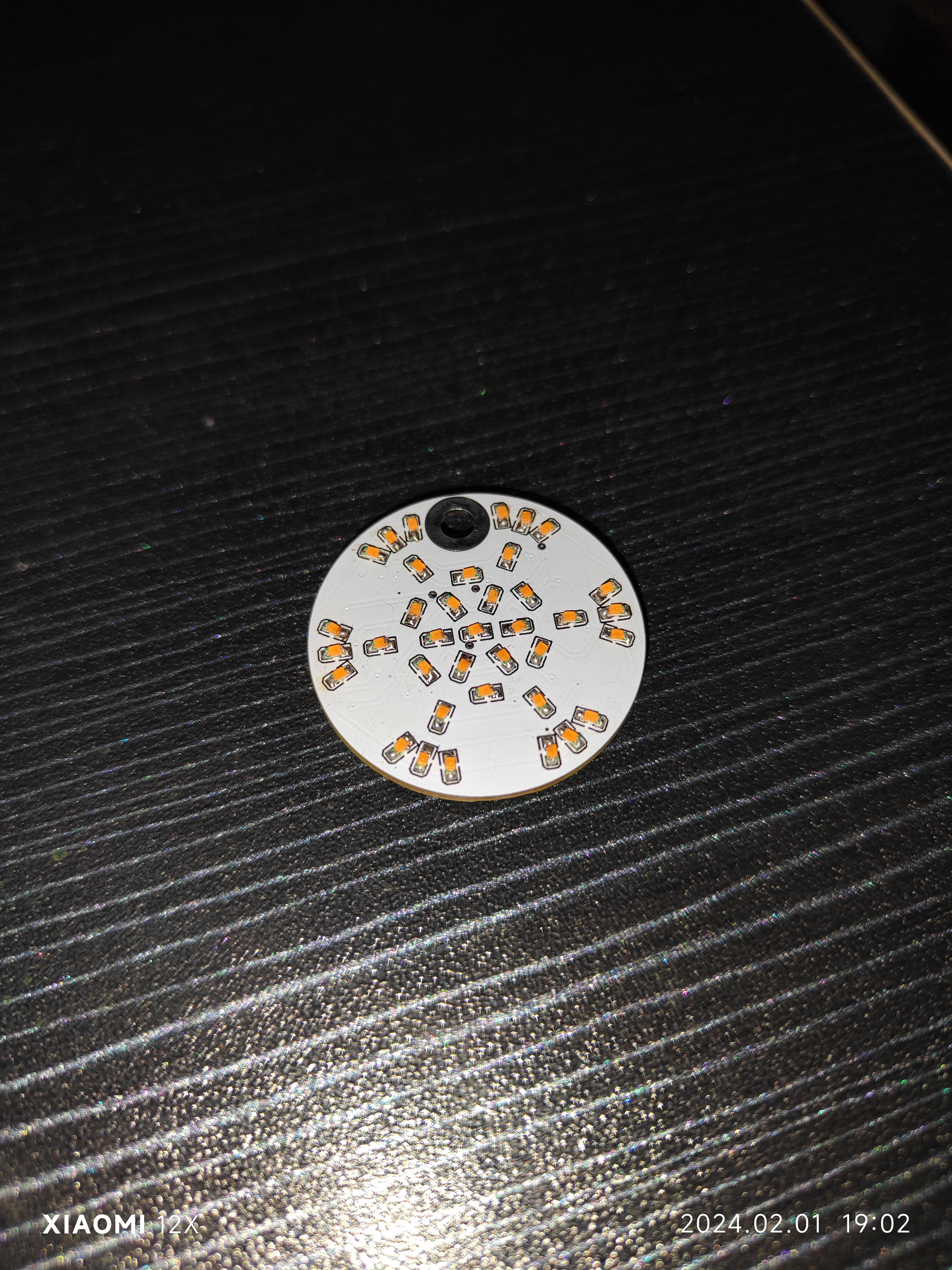
of the circuit is relatively simple. It has five LEDs from the inside out. Pins P31, P32, P33, P54, and P55 of the STC8G1K08A are used for PWM control of the LEDs. When the pin is high, the LED is off; when it is low, the LED is on. Pin P30 is set as a falling edge interrupt to capture the falling edge of the TTP223 output when a finger touches the circuit.
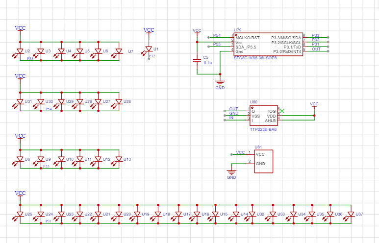
I didn't use a current-limiting resistor here, partly because I felt it made the circuit a bit dim during the verification phase, and partly because it's brighter without a resistor when using battery power, and it also reduces the number of components.
For the battery, I chose a CR1220 because I didn't want it to be too thick or too large. The battery base is also relatively small and thin, and it's a surface-mount device; the only downside is that I had to design the package myself. The overall
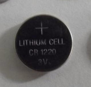
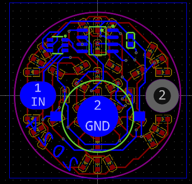
PCB
schematic design isn't difficult. Just pay attention to the layout and wiring, and leave a metal touch area, which can be replaced with a solder pad.
I created a large, multi-layered pad on the right side of the PCB to allow the finished product to be threaded through a rope as a small pendant. This pad can be removed if the pendant is not needed.
The source code documentation
uses Keil 4, not Keil 5. Theoretically, development with Keil 5C51 is similar, the development approach is the same, but some modifications might be needed; please search online for more information.
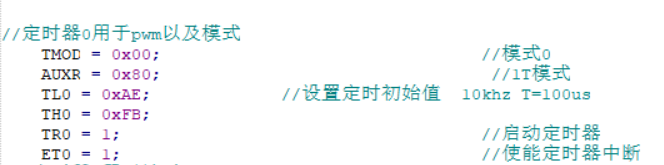
The STC8G1K08A only has 3 PWM pins, which is definitely insufficient, so a timer is needed for custom PWM control.
My PWM approach is as follows: First, set the timer to 10kHz, with a clock period of 100µs, denoted as t. Controlling the LED's on/off state by a small number of t's within 100 clock cycles (10ms, denoted as T) achieves different duty cycles for PWM output.
For example, assuming LED1 is lit for 10 small t's within one T, then LED1's duty cycle is 10%.
Of course, this approach may have drawbacks, such as potentially high power consumption, which can be optimized.
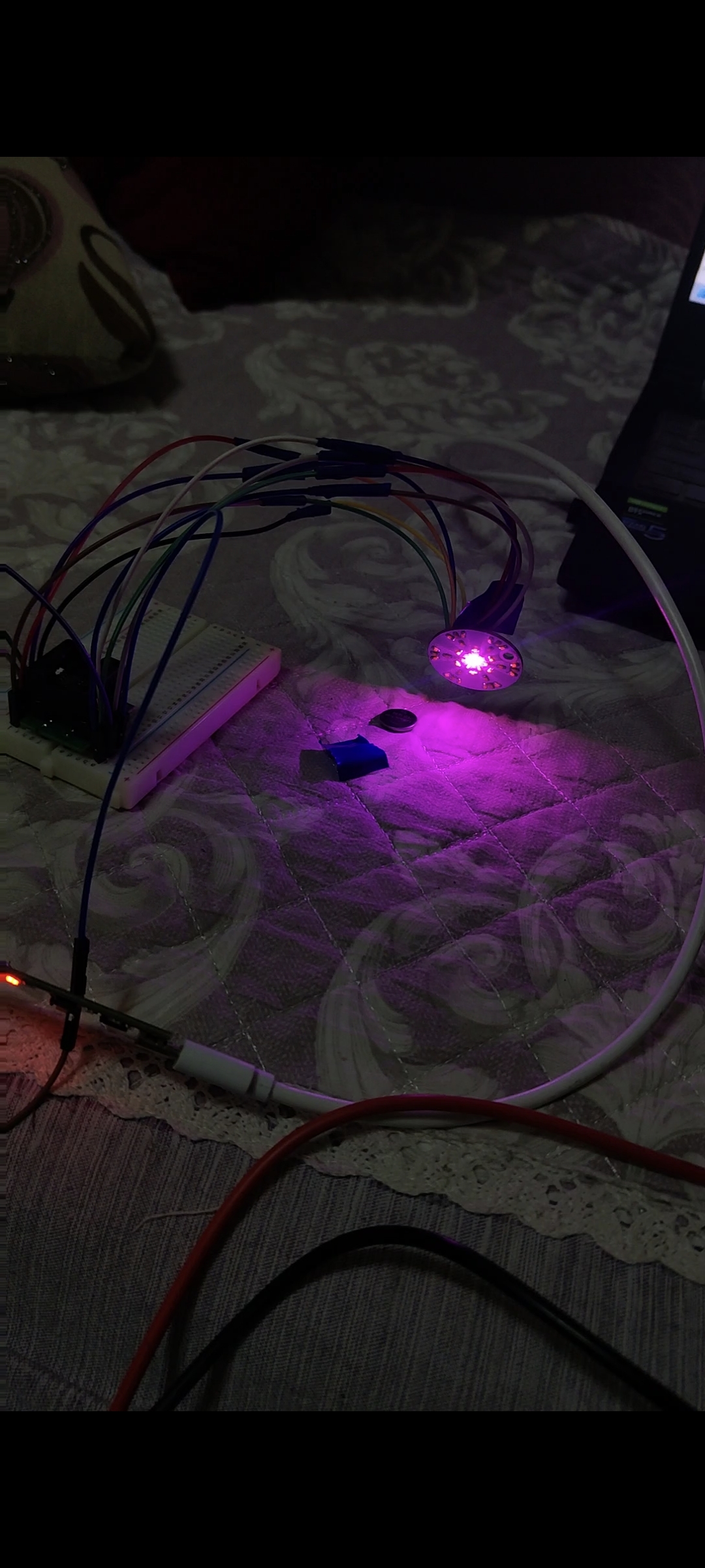
The main operating logic is as follows: after power-on initialization, the run_flag flag is set to one, and the program runs normally. When a finger is pressed, an interrupt is triggered, and after a certain period of time (500ms), the mode value is incremented by one. The mode value determines the snowflake light mode:
mode=1: gradual change, the LEDs light up sequentially from the inside to the outside, and then turn off sequentially from the outside to the inside;
mode=2: global breathing, all LEDs go from on to off and then on again;
mode=3: strobe, the LEDs flash on and off at a very fast frequency. I found it too flashy and dazzling, so I lowered the brightness. You can increase it according to your needs;
mode=4: constant on, as the name suggests, all LEDs are always on.
mode=5: Enters power-saving mode, all LEDs are off, and the clock stops
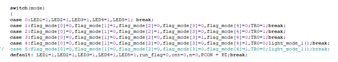
. To detect if a finger is pressed via an interrupt, P3.0 needs to be set to falling-edge interrupt (this pin interrupt can only be triggered by the falling edge). During normal operation, the run_flag bit is 1, and it increments by 1 with each press of mode. When mode is 5, power-saving mode is entered, and the run_flag bit is set to zero. When the finger is pressed again, it needs to be held for 2.5 seconds to restart normal operation. Theoretically, restarting should be done by combining it with another idle timer 1, but I haven't worked with these things for more than half a year, and I'm not particularly familiar with 51 microcontrollers and register-based programming, so I used this delay function method for detection.

The code for modes one to three is placed in the interrupt function of timer 0. The duration of each mode can be changed by modifying time_ms.
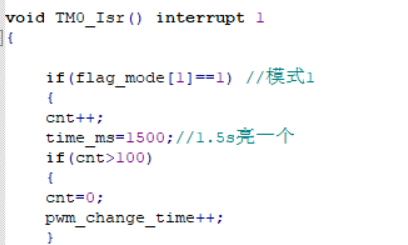
There are also some custom functions, which are relatively simple and can be modified and encapsulated as needed.
Programming instructions:
Programming is done via serial port using stc-isp-v6.92C (other versions are also acceptable).
Since I designed a verification board first and verified that the schematic and source code were correct before designing the final snowflake LED version, I didn't leave any programming ports in the PCB design for the sake of aesthetics.
Therefore, I needed to use wires to bring out the pins of the pads and then use an SOP8 programmer for programming. See the image below: [
Image of SOP8 programmer (note: select "narrow body" when purchasing)]

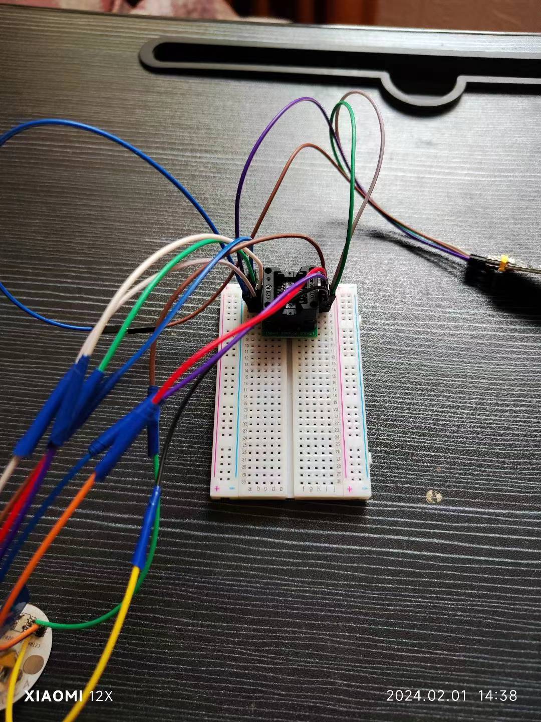
. (You only need to connect the programmer socket with a PCB jumper wire, and then program the chip via serial port. After all chips are programmed, you can solder them.)
Honestly
, I personally prefer the New Year's red color scheme; maybe I've just seen too much white lately and am aesthetically fatigued. I will upload
the other
source code to the Gitee platform and in the attachments; feel free to download it if needed.
Why isn't the PCB showing up? (Annoying~_~)


 京公网安备 11010802033920号

 1M1-SP4-R6/2-1VS4RE


