This project is based on a commercially available magnetic levitation module, aiming to enable controlled rotation of the rotor, with the goal of creating a magnetically levitated turntable. Several solutions were considered:
1. Adding magnets to the side of the float and using a motor to attract them (requires a motor, very cumbersome);
2. Adding two magnets below the float, with two coils below that detect the magnets and kick them to maintain rotation (not fully controllable, only one or two kicks per revolution);
3. Injecting a sine wave into the magnetic levitation coil control, which might get it rotating (maybe);
Finally, a brilliant solution came to mind: an axial magnetic field motor. A set of alternating N and S magnets is added to the float, driven by a PCB motor below. It's thin and suitable. Let's get started!
Features:
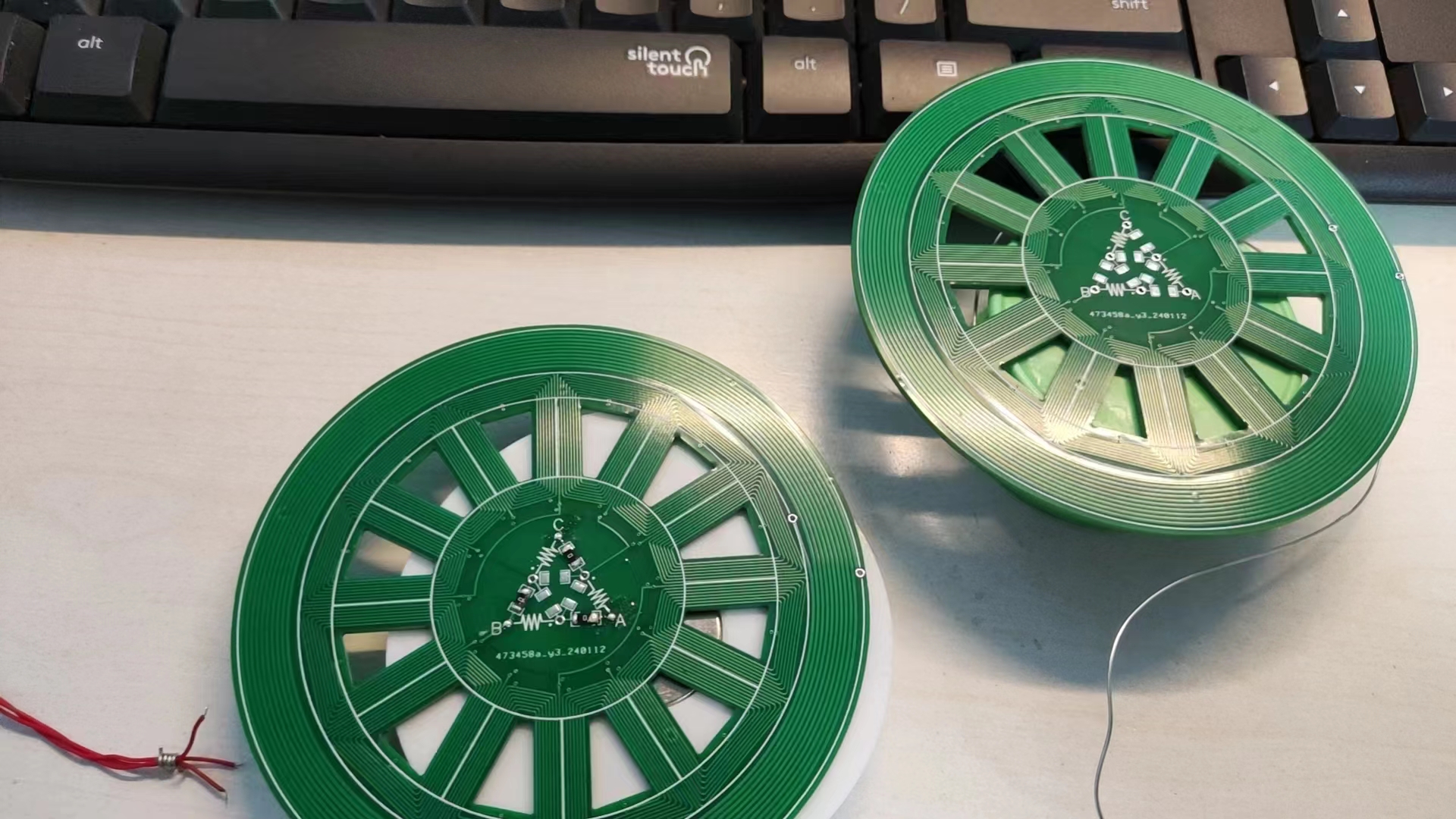
1. 12-slot 20-pole motor (magnet 15*5*2mm, purchase link: Neodymium iron boron strong magnet rectangular magnet high strength long strip magnet rare earth permanent magnet - Taobao (taobao.com)), motor winding calculator (Motorwicklungsschema berechnen (maltemedia.de)), coil characteristics are R single-phase resistance 27.3Ω, 0.38A@12V. However, the magnetic force of a single four-layer PCB is too small to control the levitation distance. Two PCBs need to be connected in parallel (specifically: solder two PCBs with delta connections, and then connect the inputs of the two boards together), 9.8Ω, 1.1A@12V. However, the distance is still less than 1cm for levitation, and the circuit needs to be raised by one more layer of board thickness.
Process: The motor coil is drawn by sketching in SolidWorks, then exporting a high-precision DXF, and then importing it into JLCPCB EDA as a single layer. Then, the second layer is obtained by horizontal mirroring. The third and fourth layers are similar. Then, the multi-layer coils are connected through through holes. The effective length of the coil is 15mm, which is the length of the magnet. The inductor spiral is done in the same way.
The windings are obtained through the winding calculator above. It is necessary to connect the same and opposite ends of the windings. This can also be derived by drawing a motor model. I used Geometer's Sketchpad:

2. Magnetic levitation float: Purchase a 500g load float (purchase link: Float 150g 300g 500g Magnetic Levitation Magnet DIY Strong Magnet Neodymium Iron Boron - Taobao (taobao.com)).
Process: This part is drawn in SolidWorks, and then exported as a Step model for 3D printing. When the magnet slot is about to be sealed, the printing is paused, and then the magnets are pasted. The magnets are NS alternating and pasted with 502 glue. As shown in the figure. A space is reserved in the float to place the wireless power supply coil, but it is not placed in the figure. A printed disk is used as a placeholder.

3. The center is changed to star or delta connection of the motor through a 0Ω resistor. The uppercase ABC ports are the motor's external output ports.
4. Add a wireless power supply inductor coil around it, approximately 20uH (theoretical value, no actual measurement). Calculator links (1. Planar spiral coil inductor calculator (circuits.dk) 2. PCB planar coil inductance value online calculation tool - RFID, NFC antenna design (edatop.com)). Number of turns (n): 10; turns Spacing between turns (s): 254um; Turn width (w): 508um; Outer Diameter (dout): 97240um. This part of the circuit was purchased (purchase link: Magnetic levitation wireless power supply module wireless power supply light moon light globe DIY accessories long distance - Taobao (taobao.com)).

The files include: PCB motor file *1, SolidWorks float model file *1, SolidWorks coil model file *1.


 京公网安备 11010802033920号

 MBM29F033C-12


