The AT32F403A series microcontrollers, developed by the AT32F403ACGT6 development board, are based on the high-performance ARM® Cortex®
-M4 32-bit RISC core, operating at frequencies up to
240 MHz. The Cortex®
-M4 core includes a single-precision floating-point unit (FPU), supporting all ARM® single-precision data processing instructions
and data types. It also features a set of DSP instructions and a memory protection unit (MPU) for enhanced application security.
The AT32F403A series incorporates high-speed memory (up to 1024 KB of RAM and 96 + 128 KB of SRAM) and can
utilize external memory (up to 16 MB of SPI flash), rich enhanced GPIO ports, and
peripherals . The built-in memory allows for arbitrary range program area protection by sLib, creating a safe execution code library.
The AT32F403A series provides three 12-bit ADCs, two 12-bit DACs, eight general-purpose 16-bit timers, two general-purpose 32-bit
timers , and up to two PWM timers. They also come with standard and advanced communication interfaces: up to 3 I
2C interfaces, 4 SPI interfaces
(multiplexed as I
2S interfaces), 2 SDIO interfaces, 8 USART/UART interfaces, 1 USBFS interface, and 2 CAN interfaces.
The AT32F403A series products operate in a temperature range of -40 °C to +105 °C, with a power supply voltage of 2.6 V to 3.6 V, and a power-saving mode to ensure
the requirements of low-power applications.
Many flight controllers now also use this microcontroller solution, which is worth learning. The official tutorial is really super detailed.
Highlights:
up to 240MHz frequency
, M4 core,
FPU floating-point operation, supports
expandable SRAM
, supports external SPIM Flash up to 16M
, can read and write API libraries, can be encrypted,
can run code in external Flash,
rich official information

, ZW = zero wait-state, up to SYSCLK 240 MHz,
NZW = non-zero wait-state
(2) supports internal flash memory and SRAM allocation through user system data settings. Taking AT32F403AVGT7 as an example, the internal flash memory and
SRAM can be configured as follows:
ZW: 256 K bytes, NZW: 768 K bytes, SRAM: 96 K bytes;
ZW: 128 K bytes, NZW: 896 K bytes, SRAM: 224 K bytes.
(3) SPIM = External four-wire SPI Flash memory extension (program execution/data storage/program and data can be encrypted).
(4) LQFP64 package XMC only supports driving 8-bit mode LCD screen.
(5) Half-duplex I
2S and SPI functions are multiplexed.
(6) LQFP48 and QFN48 packages do not have UART8, and USART6 can only be used as UART because it lacks the CK pin.
(7) LQFP48 and QFN48 packages only have SDIO2, which supports up to 4-bit (D0~D3) mode.
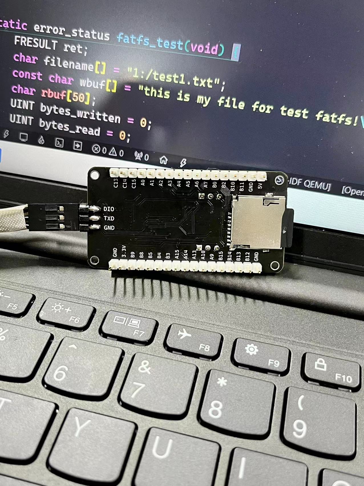
Onboard peripherals include an
external 16M SPIM four-wire SPI flash memory, an
SD memory card with SDIO protocol
, an LED controllable by GPIO
, a user button,
a system reset button,
and two jumper pins (Boot1 and
0). The crystal oscillator is selectable up to 25M, but 8M is recommended.
An SWD download port is provided, supporting DAP-LINK, JInk, and the official ATLINK
serial port.
The bundled example code package shows
that all peripherals on the development board have been successfully verified.
A Keil 5 project is provided on GitHub for easy code verification:
Github: https://github.com/ccy-studio/CCY-AT32-Example
. I also have a dedicated AT32 learning notes section on my personal blog (continuously updated):
https://www.saisaiwa.com/tags/at32
col
col
col


 京公网安备 11010802033920号

 NT90TPNLADDC15VI


