Demo video
on Bilibili: Making a Chameleon Lite Star Trails Skin.
You
can check out the original project (Github: RfidResearchGroup/ChameleonUltra) for the
schematic. Just copy it directly, replacing only some component packages based on the shape. All software is compatible. See the original project for usage instructions.
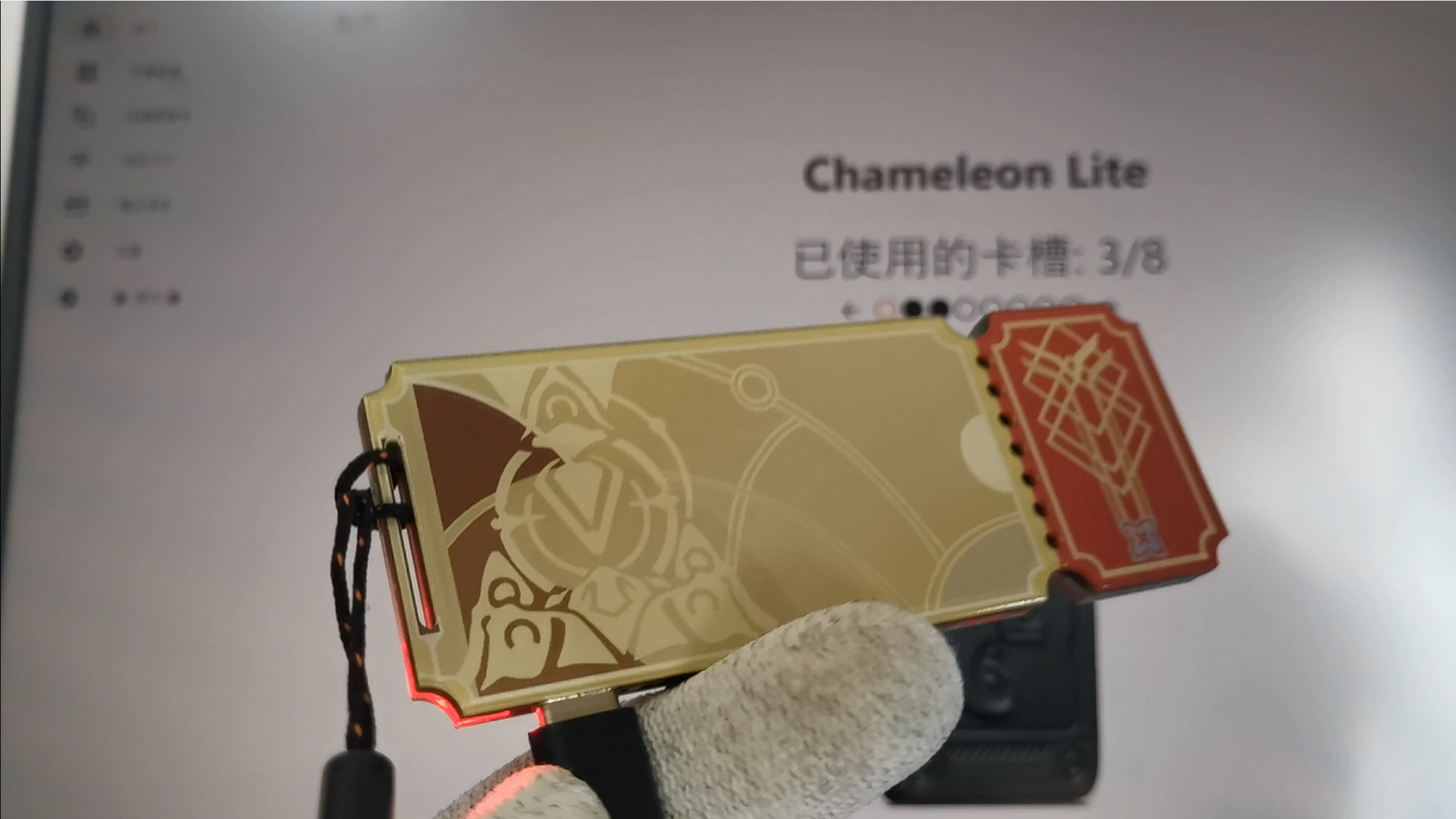
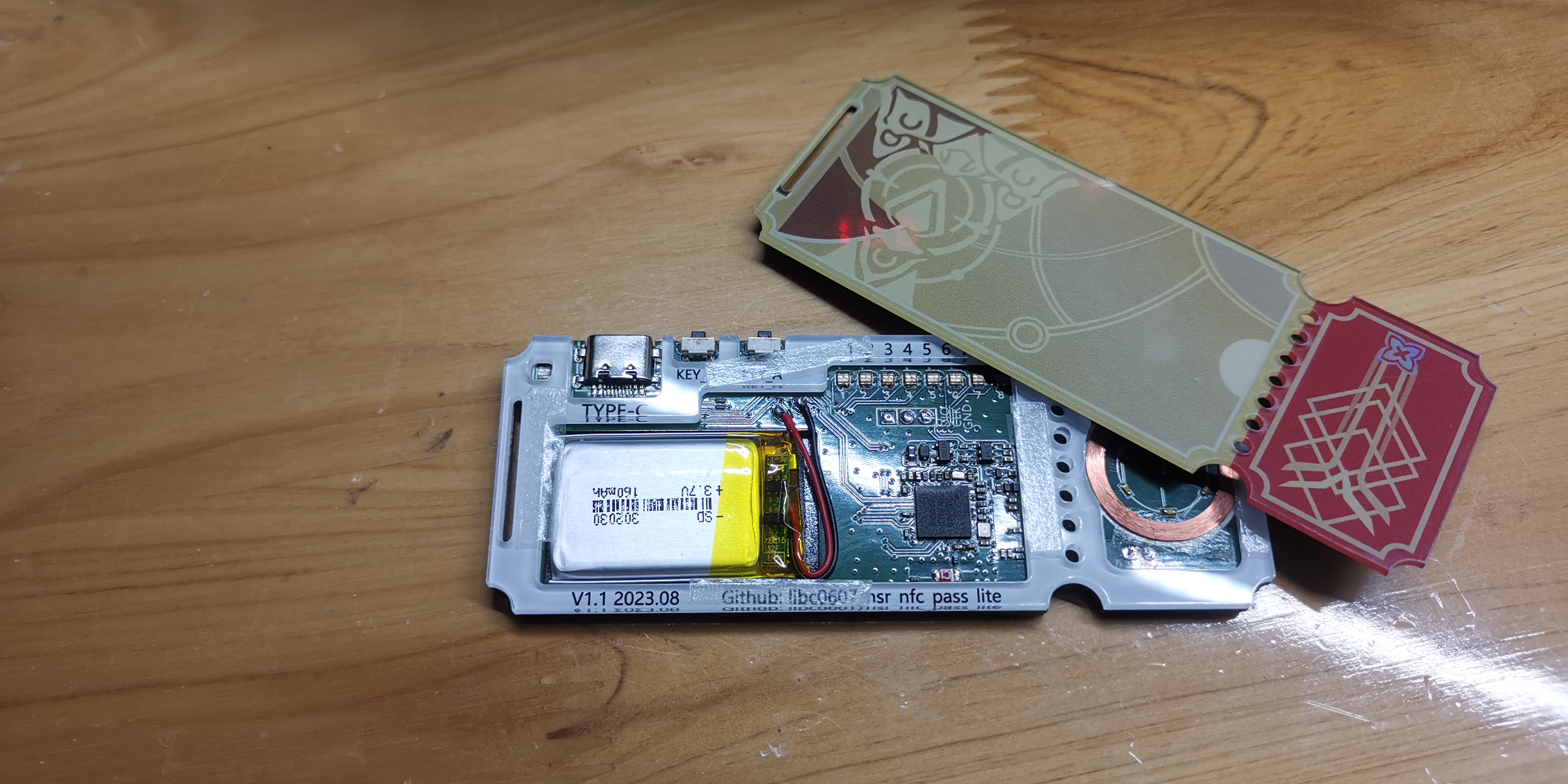
Image materials are from Bilibili UP @刃下狼血, with minor modifications . Due to the thickness of the recessed Type-C
PCB structure, the prototyping thickness can only be 1.6mm. For the four-layer 7628 structure , I recommend choosing black solder mask, otherwise it looks a bit greenish. The dimensions are 100mm * 38mm. Because I was too lazy to modify the image materials, it's slightly thinner than some other designs, but the impact is minimal and it makes hand soldering easier. You'll need a teppanyaki grill and a hot air gun, and I recommend at least creating a small stencil for the nRF52840 for ball mounting. Recessed Type-C PCB. There are many types of pin positions. You can buy the corresponding part number at LCSC Mall, or on Taobao. I remember a store called Yijian Electronics sells the same design, and you can also buy a button along with it. Regarding the LF (125 kHz) coil, due to physical size limitations, don't expect the LF coil to work very well. If you want to use the LF, it is recommended to make the original version, or modify the structure to fit a larger coil. Currently, the only effect is that it can read (sadly). The resonant frequency of the coil inductor and two resonant capacitors in parallel should be around 125kHz (just use a calculator?). The coil of the 345uH inductor commonly used in ID card readers, with 1nF and 3.3nF in parallel, is about 20mm. It is not easy to buy a coil. You can buy a 15mm coil, which is more common on Taobao. The reader coil is replaced, but the reading range becomes more unpredictable; the thickness cannot exceed 2mm, otherwise it will not fit the cutout of the reference panel. You can try inserting any coil of similar size and modifying the capacitor to achieve approximate matching . The coil internal resistance cannot be too large, otherwise it will not generate enough load during modulation; however, you can try modifying the resistor connected in series with the modulation NMOS to a smaller value to improve the resonant capacitor. The HF (13.56 MHz) coil board needs to be drawn with C0G/NPO material. The calculator shows it should be around 2.7uH. The card reading effect is better than LF. The schematic is directly copied. The actual resonant capacitor capacity can be optimized and reduced. Refer to the NORDIC document nWP-026: nRF52832 NFC Antenna Tuning; however, the schematic shows adding capacitors to ground separately. You need to remember to roughly divide by 2. This only gives a relatively common method. For others, please refer to the original project document. Flash the SWD for the first time, because it has a Bootloader and other components in addition to the main body; afterwards, it can be accessed via USB. Alternatively, you can upgrade via Bluetooth (Note: As of January 13, 2024, the Bluetooth version 2.0 Release on GitHub has some issues and cannot be found; you can also see the same problem in the issues section; however, flashing Basic Factory Firmware allows Bluetooth to work, so you can use this method to verify the Bluetooth hardware first). Find any debugger that supports SWD (such as your old, unused Heco). Connect SWDIO/SWCLK/GND to the board and find any OpenOCD that supports this debugger and nrf52. Like Chromium, you probably already have several on your hard drive. For example, I used the one I found in MounRiver Studio to power the board and connect the debugger to my computer . Download the firmware from the lite-binaries on GitHub. Because I was lazy, I simply put fullimage.hex in the openocd/bin directory . Execute the following command in openocd/bin: openocd -f interfacecmsis-dap.cfg -f target rf52.cfg -c "program fullimage.hex verify After resetting and shutting down the board, it should be able to connect to the GUI host computer. The casing (panel) project includes three panel documents: top, bottom, and middle. The top and bottom panels can be 1.0mm thick; the middle layer thickness depends on the battery thickness: if using a standard 302030 lithium battery, a 2.0mm thick middle layer is sufficient, resulting in a total thickness of no more than 6mm after assembly. Thicker batteries like the 402030 are also acceptable, simply increasing the thickness of the middle frame accordingly. All three documents are based on LCSC's 200mm * 300mm dimensions. One sample of each can make 10 finished products. If you only need to make three or fewer finished products and only want to order one panel, you can consider assembling it yourself, making the top and bottom panels 2.0mm thick and combining them into one unit. This would result in a total thickness of approximately 8mm (not particularly thick...?). The middle layer text indicates the buttons and lights, which are visible from the side, albeit slightly flattened. It's better than having no markings at all. Of course, you can also choose to only cut the panels to save time and attention on the top... This is not the same file as Bottom. It's symmetrical. If you've combined them, be sure to write the direction in the blank space to indicate they are different, because the actual printing order will likely also be combined, and if you don't write it, they might just copy it randomly. I've encountered a situation where symmetry was overlooked once. When ordering the panel, select bottom-side printing for scratch resistance, don't select strong light blocking, because this will prevent the card reader light from shining through (sad). It's recommended to choose one with adhesive backing for easy application, or you can glue it yourself, for example, by buying a roll of 3M 9448; theoretically, the middle circuit part is sealed, so moisture shouldn't be able to get in after gluing, but the charging port and buttons will be exposed, I haven't figured out how to handle that yet (if it breaks, I can just replace it). ( For the assembly structure, refer to the video or schematic diagram for the stacked structure, just glue it in place. Open source license & The sensing distance is definitely not as good as the original, but it can be flashed. I made this mainly out of curiosity and to use up panel vouchers, aka just for fun. If you just want a finished product, I don't recommend making this. You can consider buying or replicating someone else's. I also hope you can express your support for the developers who are maintaining this project. DIY is risky, please order with caution, especially the nRF52840 package. Please at least make sure you can hand-solder this before considering the hardware (PCB + panel). The open-source license is the same as the original project, GPL 3.0, but because I'm too lazy to solder this amazing package, I don't plan to sell it. In other words, after releasing the open-source version, it's just sitting around doing nothing. I don't claim any rights to the images used. If you want to sell it, you might need to ask the uploader and mhy.
Please only use this tool to learn NFC/Bluetooth/embedded development, etc. Do not use it for anything inappropriate; if you do, it's none of my responsibility. Thank you. (
Some images
are attached.) *Note: The middle layer in this image represents the previous version. The text position in the open-source version has been slightly adjusted for easier observation.
PDF_Chameleon Lite Collapse Iron Star Trail Special Ticket Skin Version.zip
Altium_Chameleon Lite Collapse Iron Star Trails Exclusive Ticket Skin Version.zip
PADS_Chameleon Lite Collapse Iron Star Trail Special Ticket Skin Version.zip
BOM_Chameleon Lite Collapse Iron Star Trail Exclusive Ticket Skin Version.xlsx
96285
Application of intelligent voice control (fish tank) module
This smart voice control (fish tank) module is a multi-channel voice control module, using the HLK-V20 module as its core. It allows for independent control of multiple channels. Overall, it's quite interesting. It could be used for smart fish tanks, smart home décor, and more.

The core uses the HLK-V20 module to create a multi-channel voice control module for offline home voice control. It allows for independent control of multiple channels. My wife isn't a big fan of fish, saying they're boring because they can't talk, so I decided to get a smart system for the aquarium, providing remote voice control for adding water, changing water, aeration, lighting, feeding, etc. It's similar to a smart voice speaker, enabling precise multi-channel voice control. It can even make some sounds; overall, it's quite interesting. A smart aquarium.
The module has some redundant design features. It's necessary to consider the usage of other parts of the module, so some seemingly unnecessary parts are actually carefully reserved. This facilitates future adaptation to different relays, different power supply methods, and devices controlling different voltages. The passive design allows for adjustment of normally open and normally closed states by adjusting the soldering points to the relays. It also allows for selection of whether the device is on or off when energized, making adjustments based on the actual operating time of the equipment.
For low-voltage, low-current applications, a low-voltage drive of around 12V and 0.5A is sufficient, even down to the transistor. For higher voltage and current requirements, a relay is necessary for safety and reliability. It can generally drive 40W or 60W lights without issue. To drive high-power appliances like kettles or air conditioners, a low-voltage-to-high-voltage control is required at the end. Connect an AC contactor to the drive to prevent damage to offline devices.
Extension:
The design allows you to customize control command names and wake-up methods. Connect the corresponding devices and appliances as needed (do not operate high voltage without proper training to avoid danger). Voice wake-up association is also possible for two or more devices, which is particularly suitable for multi-device use and allows for modular management of areas. For example, after offline voice wake-up in the living room, it can be set up to issue a wake-up word to wake up other modules, making smart offline whole-house control possible. Those interested can try it out, paying attention to distance and word settings.
BOM_Board1_Schematic1_2022-12-06.xlsx
Screenshot 20221206153354.png
USB_Update_Tool_User_Guide.pdf
chaunkoushengjigongji.rar
Intelligent Voice Control (Fish Tank) Module Program.docx
Default module test verification video.mp4
PDF_Intelligent Voice Control (Fish Tank) Module Application.zip
Altium Smart Voice Control (Fish Tank) Module Application.zip
PADS_Intelligent Voice Control (Fish Tank) Module Application.zip
BOM_Intelligent Voice Control (Fish Tank) Module Application.xlsx
96286
electronic


 京公网安备 11010802033920号

 S29AL004D90BAI010


