Wide input voltage range: 5.5V to 36V;
Up to 5A continuous (6A peak) output current;
Greater than 90% efficiency achieved through a 110mΩ integrated MOSFET switch;
Wide output voltage range: Adjustable down to 1.22V with 1.5% initial accuracy;
Internal compensation minimizes the number of external components;
Suitable for small filter sizes; Fixed 500kHz switching frequency;
18µA shutdown current;
Improved line conditioning and transient response through input voltage feedforward;
System protected against overcurrent, overvoltage, and thermal shutdown;
–40°C to 125°C operating junction temperature range
; Utilizes a small, thermally enhanced 8-pin SOIC PowerPAD™ package;
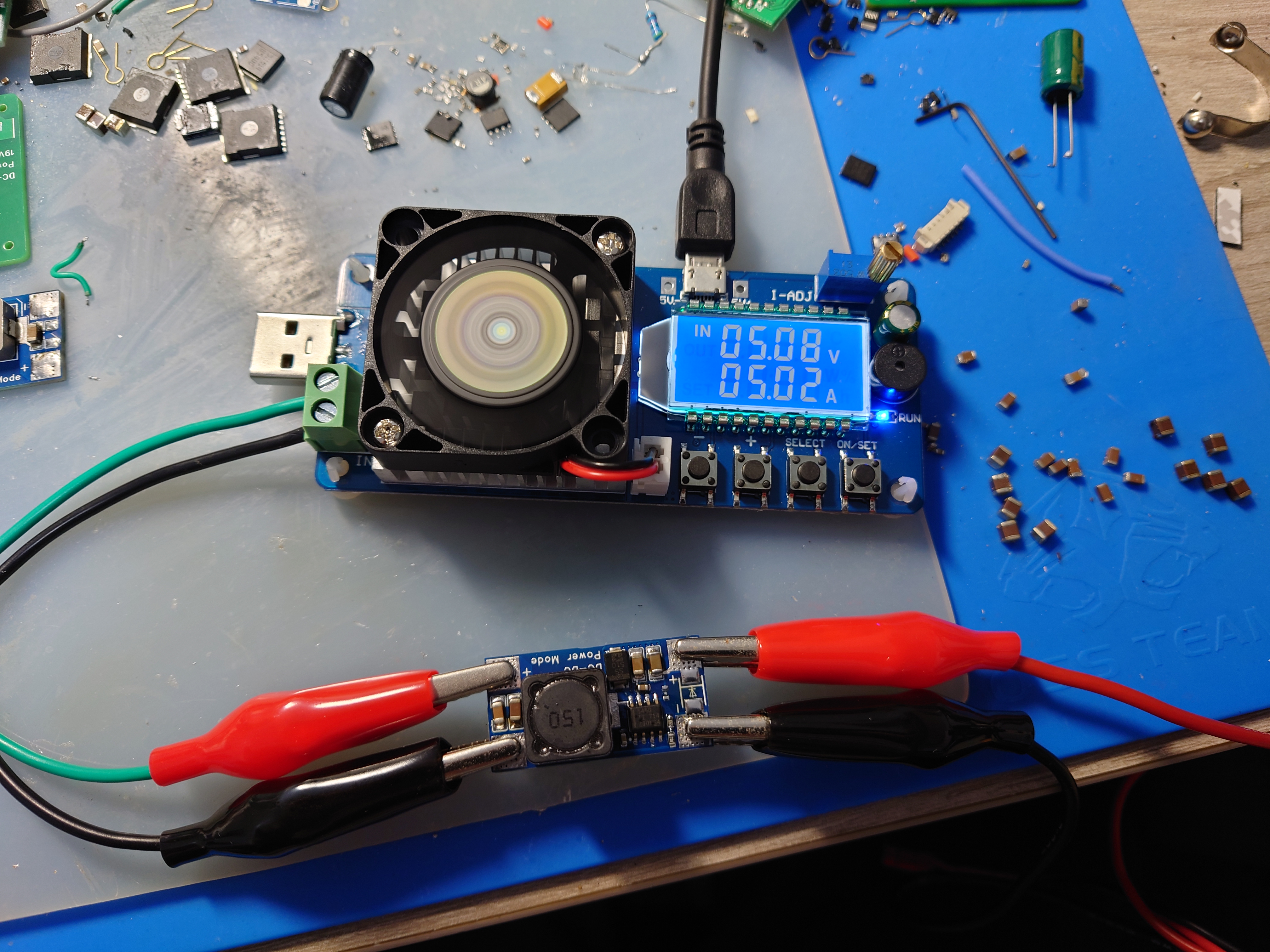
Input 24V, Output 5.3V 5A tested and working; Enhanced cooling is required for long-term full-load operation.
tps5450.pdf
PDF_TPS5450 step-down module verification board.zip
Altium_TPS5450 step-down module verification board.zip
PADS_TPS5450 step-down module verification board.zip
BOM_TPS5450 step-down module verification board.xlsx
96806
ROS Ackerman Simplification
This is a simplified control board for the lower-level machine of an Ackerman ROS robot. It's a beginner's drawing board and not very mature.
Includes an STM32C8T6 minimum system board, motor drive module, MPU6050/6500, MINI560 step-down module, DRV8833 motor driver, and a reserved Bluetooth interface. It can implement basic functions as a lower-level controller for ROS vehicles. Because it only provides two motor interfaces, one motor module, and one PWM interface for controlling the servo motor, it can be used as a control board for Ackerman vehicles. It can also be modified to control two-wheel differential vehicles and other types of vehicles as needed.
PDF_ROS Ackerman Simplified.zip
Altium_ROS Ackerman Simplified.zip
PADS_ROS Ackerman Simplified.zip
BOM_ROS Ackerman Simplified.xlsx
96807
LM5122 Boost Module 12V to 24V 5A Dual Phase - [Refer to Official Layout]
LM5122 12V to 24V dual-phase module
This is a 12V to 24V module based on the LM5122QMHX boost converter chip, with layout and parameters automatically generated by TI tools.
Theoretically, it can output 10A of high current with a 240W load, but the actual output depends on the components used; without a load tester, the exact figures are unclear.
The inductor used is a domestic PQ2615, 10uH 30A.
An extended dual-phase interface is provided, with wiring instructions printed on the board. For extended use, the input and output need to be connected in parallel.
The extended dual-phase interface works normally in actual testing; however, its effectiveness is unknown. Further verification with an oscilloscope is needed; proceed with caution when prototyping.

PDF_LM5122 Boost Module 12V to 24V 5A Dual Phase_【Refer to Official Layout】.zip
Altium LM5122 boost module 12V to 24V 5A dual-phase [Refer to official layout].zip
PADS_LM5122 Boost Module 12V to 24V 5A Dual Phase_【Refer to Official Layout】.zip
BOM_LM5122 Boost Module 12V to 24V 5A Dual Phase_【Refer to Official Layout】.xlsx
96809
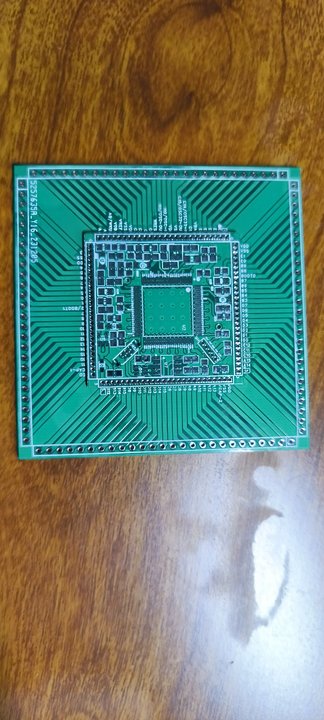
STM32F407VET6 Minimum Development Board 2.0
The STM32F407VET6 minimum system development board 2.0 has been successfully prototyped and tested, but has not yet been soldered. Optimization is currently at this stage. Discussion and guidance are welcome. (Only group: 289917684)
The STM32F407VET6 minimum system development board 2.0 has been successfully prototyped and tested, but has not yet been soldered. In previous versions, the 1.27mm header pins were found to be too expensive, so a baseboard was added to solder the core board onto it. The solder pads on the baseboard will be lengthened later for easier soldering. This is the current optimization. Discussion and guidance are welcome. (Only group: 289917684)
PDF_STM32F407VET6 Minimum Development Board 2.0.zip
Altium_STM32F407VET6 Minimum Development Board 2.0.zip
PADS_STM32F407VET6 Minimum Development Board 2.0.zip
BOM_STM32F407VET6 Minimum Development Board 2.0.xlsx
96810
electronic


 京公网安备 11010802033920号

 C0805C103Z3GAC


