 III. Functional Modules
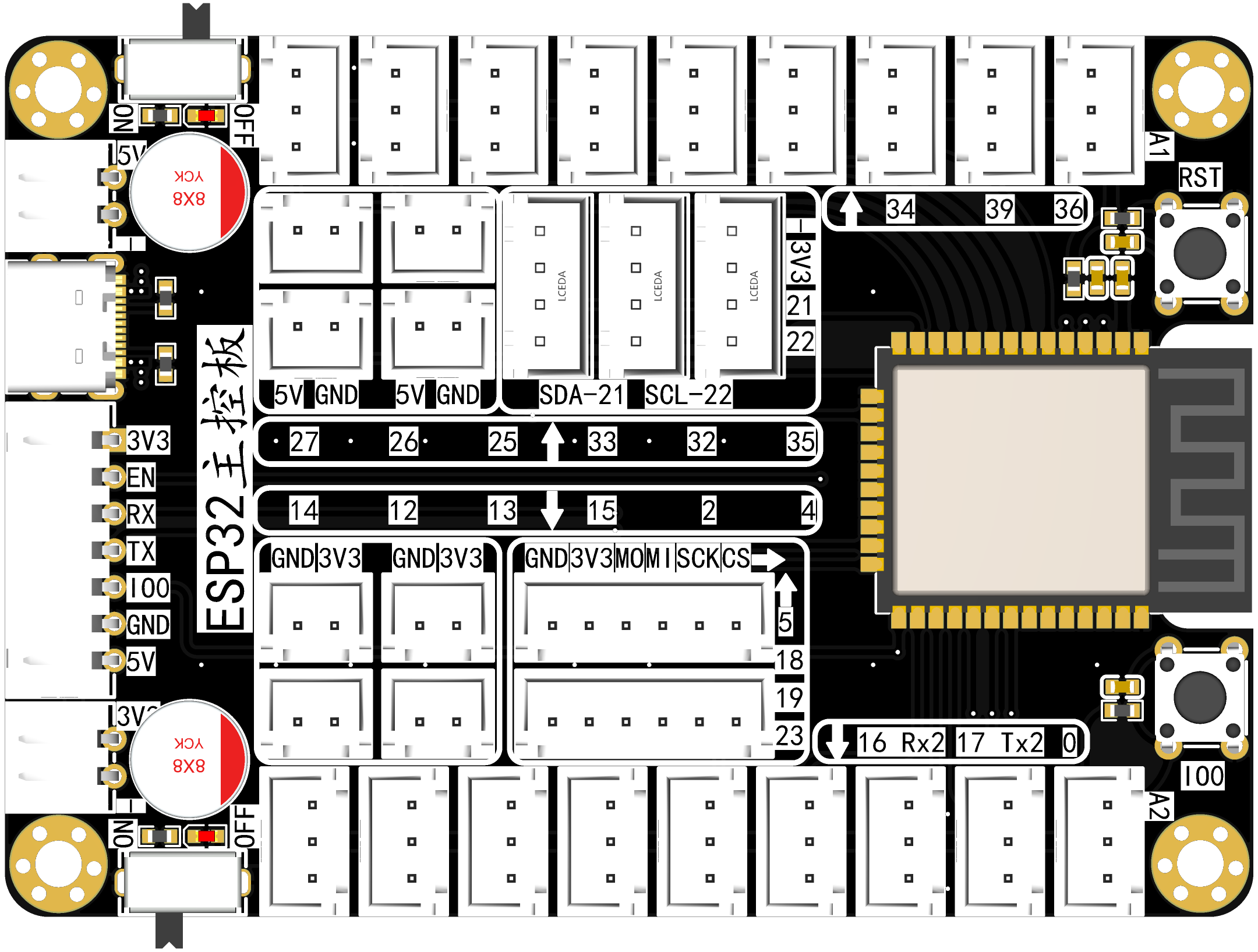
 Expansion Board Design Two power inputs: 5V and 3.3V. The 5V input uses a classic Type-C design and a 2-pin connector. The 3.3V input uses a 2-pin connector.
  One switch is designed for both 5V and 3.3V, a standard design. Indicator lights are used to indicate the switch status.
  Reset and flashing buttons are provided for greater convenience. Flashing can be performed in conjunction with the ESP32 flashing sequence.
 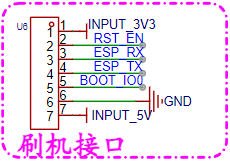 Directly connects to the ESP32 flashing board, reflecting a modular approach that reduces costs and increases efficiency.
  : The main control module uses the general-purpose ESP32-WROOM-32E, with built-in WIFI and Bluetooth modules. It features a dual-core MCU, ensuring stability and power.
 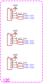 : Three IIC interfaces are reserved to meet simple application scenarios.
 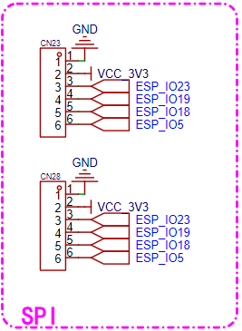 : Two SPI interfaces are reserved to meet simple application scenarios.
 Sixteen ADC interfaces are brought out, which can also be used as ordinary GPIO.
 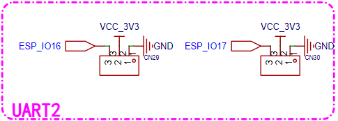 : Two UART interfaces are brought out, which can also be used as ordinary GPIO.
All reference designs on this site are sourced from major semiconductor manufacturers or collected online for learning and research. The copyright belongs to the semiconductor manufacturer or the original author. If you believe that the reference design of this site infringes upon your relevant rights and interests, please send us a rights notice. As a neutral platform service provider, we will take measures to delete the relevant content in accordance with relevant laws after receiving the relevant notice from the rights holder. Please send relevant notifications to email: bbs_service@eeworld.com.cn.
It is your responsibility to test the circuit yourself and determine its suitability for you. EEWorld will not be liable for direct, indirect, special, incidental, consequential or punitive damages arising from any cause or anything connected to any reference design used.
Supported by EEWorld Datasheet
EEWorld
subscription
account

EEWorld
service
account

Automotive
development
community

Robot
development
community

About Us Customer Service Contact Information Datasheet Sitemap LatestNews


Room 1530, 15th Floor, Building B,
No.18 Zhongguancun Street,
Haidian District,
Beijing, Postal Code: 100190
China
Telephone: 008610 8235 0740
 京公网安备 11010802033920号

 SERU2LBKRD7.62RDEEBRN


