Links:
Open source address: https://github.com/literem/led-matrix-32x32
Bilibili video demonstration: https://www.bilibili.com/video/BV17C4y1V7Po/?share_source=copy_web&vd_source=270a1be8dc034228384b848da1bf38b7
Hardware Construction
: This project is based on the ESP32 microcontroller and consists of three boards: a module board, a connection board, and an ESP32 main control board.
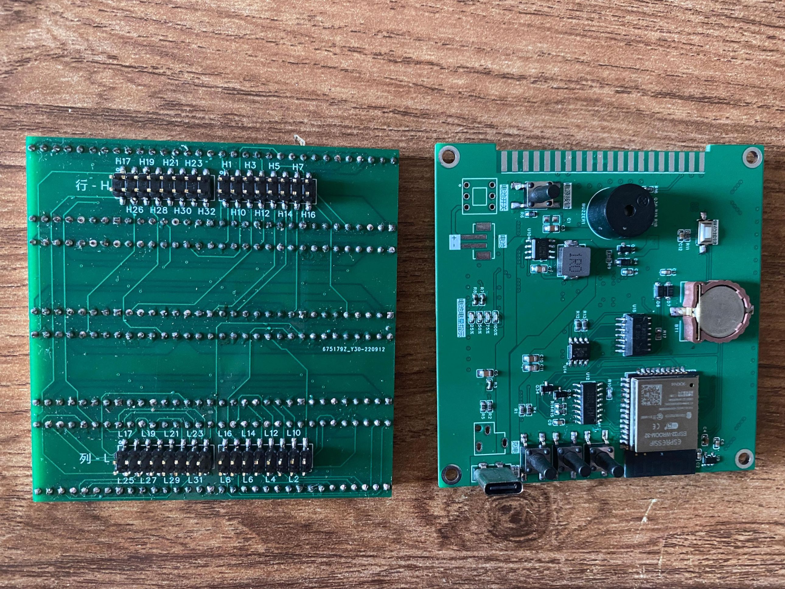
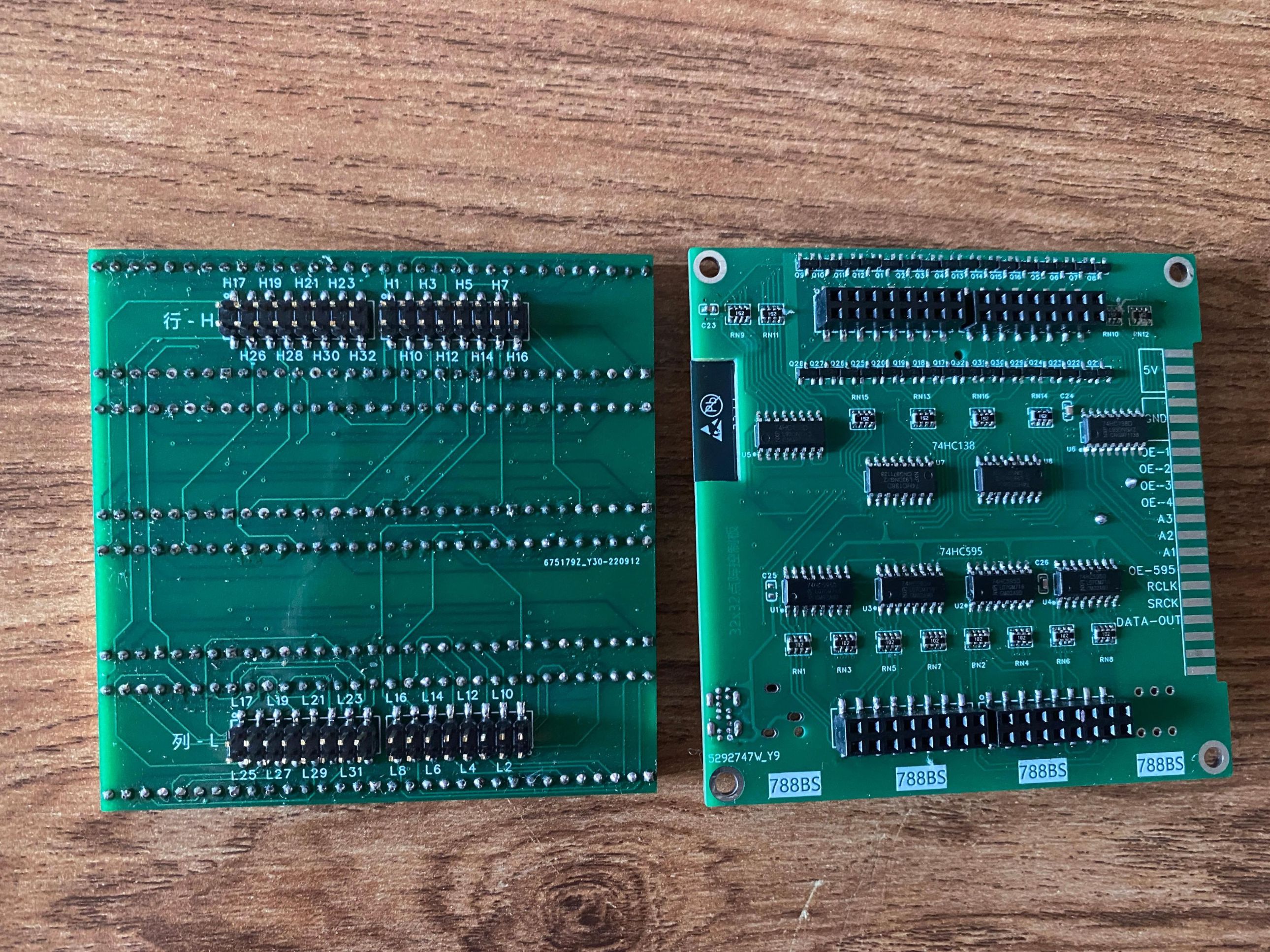
Module Board: A board that connects 16 8x8 pixel 788BS dot matrix modules. It has no chips and provides 32 row pins and 32 column pins.
Baseboard: Its function is to connect the module board. It has chip control: four 74HC138 chips control row scanning, and four 74HC595 chips control columns. The board has interfaces on both sides for data and power input, allowing for interconnection to connect multiple 32x32 dot matrix
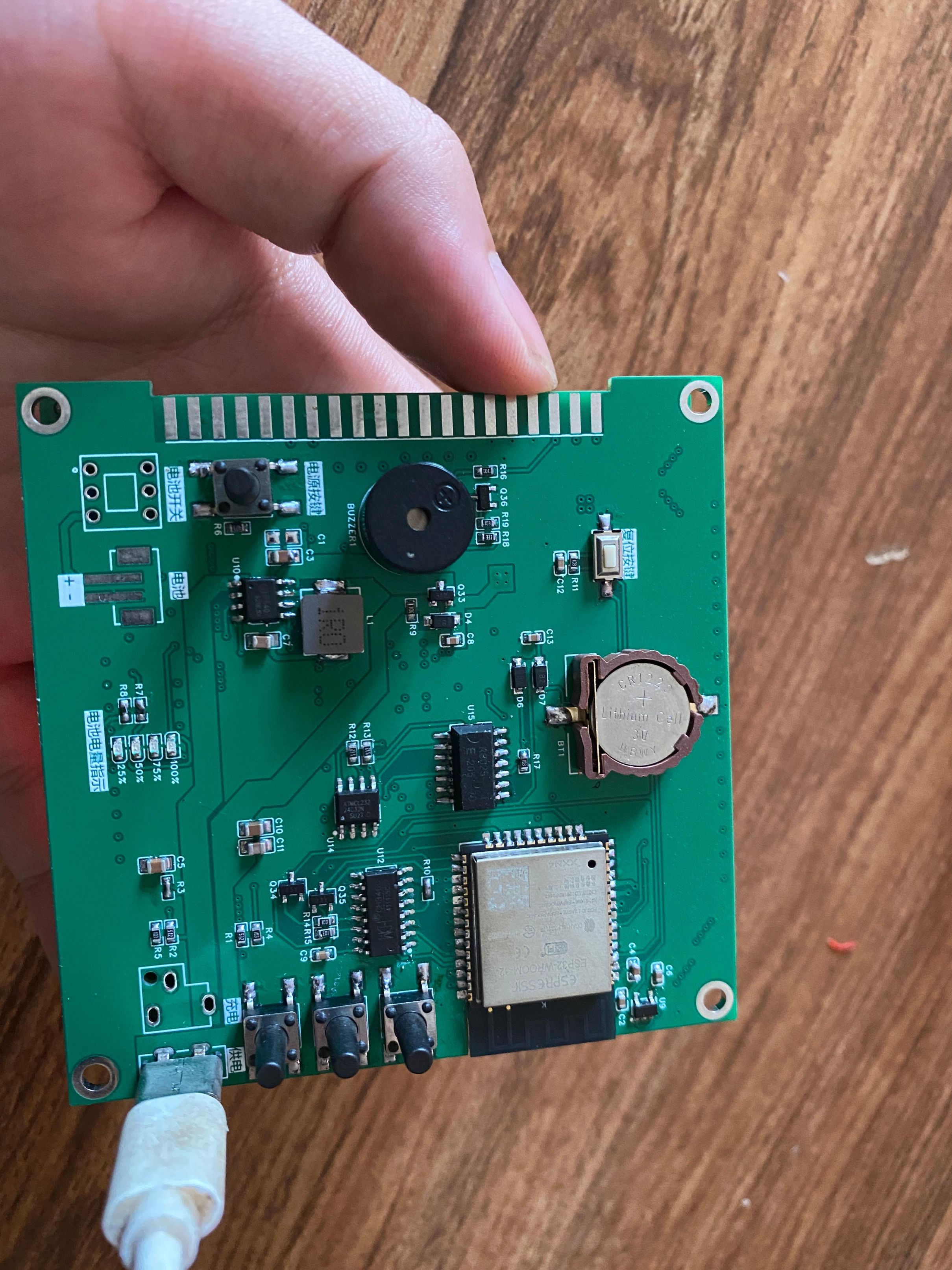
ESP32 control boards. This board combines a connection board function with an ESP32 microcontroller, an RX8025T clock chip, and a battery charge/discharge management chip. It achieves a cascading effect when connected to a base board.
Note: The base board is not used in this project because the dot matrix screen cascading is not utilized.
The function for displaying GIF images is implemented here. The ESP32 microcontroller is developed using Arduino and displays data via serial port; whatever is sent via serial port is displayed. The host computer software is written using Qt to split the GIF images, scale each image to 32x32 pixels, perform grayscale and binarization, and finally convert it into a 128-byte array. This array of multiple images is stored in a file. During playback, the byte data in the file is read and sent to the dot matrix screen via serial port. Each serial port sends one data frame (128 bytes). The host computer does not actively send data; it only sends a data frame when it receives a request from the ESP32.
Two power supply methods are available: Type-C power and battery power, with battery charging also supported. Since only GIF animation display is currently implemented, it needs to be connected to a computer's USB port, making battery power somewhat redundant. The PCB design included an RX8025T real-time clock chip, an IP5407 power management chip, and an AT24C32 memory chip, but their functions are not used in this project. Cascading multiple dot matrix screens might be useful for text scrolling.
Software
for the lower-level device: The code is compiled using Arduino IDE and downloaded to the ESP32. Compilation with version 1.8.12 worked without issues; I'm unsure if higher or lower versions will cause errors, as I haven't tested them.
The upper-level device: Developed using QT, simply unzip and run Matrix32x32.exe; it generally runs directly. Then connect the dot matrix screen, ensuring the baud rate is selected correctly (use the default).
Physical product display
: front view,

back view,
and the two boards after separation.
Demo video.mp4
PDF_A 32x32 pixel screen that can display Git animated images.zip
Altium - A 32x32 pixel screen that can display dynamic images from Git.zip
PADS - A 32x32 pixel screen that can display dynamic images from Git.zip
BOM_A 32x32 pixel screen capable of displaying Git animated images.xlsx
97248
Seven-way answer buzzer
A seven-channel quiz buzzer designed using combinational logic circuits.
Function Description:
This system uses seven digital tubes to display the scores of seven contestants, one digital tube to display the contestant who successfully answered, and two digital tubes for the countdown timer.
Seven buttons simulate seven contestants. A 74LS373 latch chip and a 74LS148 encoder chip are used to detect who answered first.
PDF_Seven-Way Answer Buzzer.zip
Altium_Seven-Way Quiz Buzzer.zip
PADS_Seven-Way Quiz Buzzer.zip
BOM_Seven-Way Quiz Buzzer.xlsx
97249
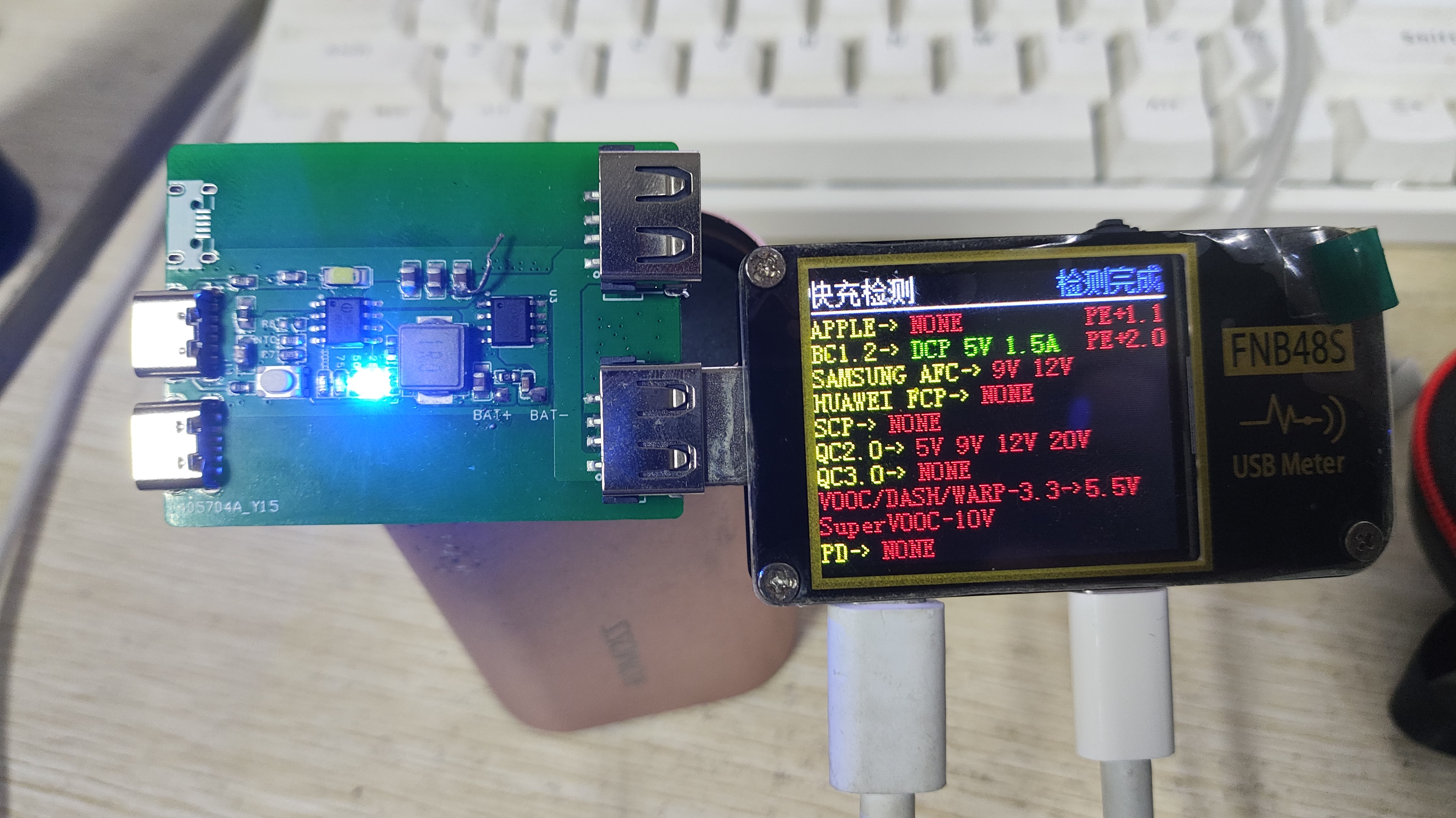
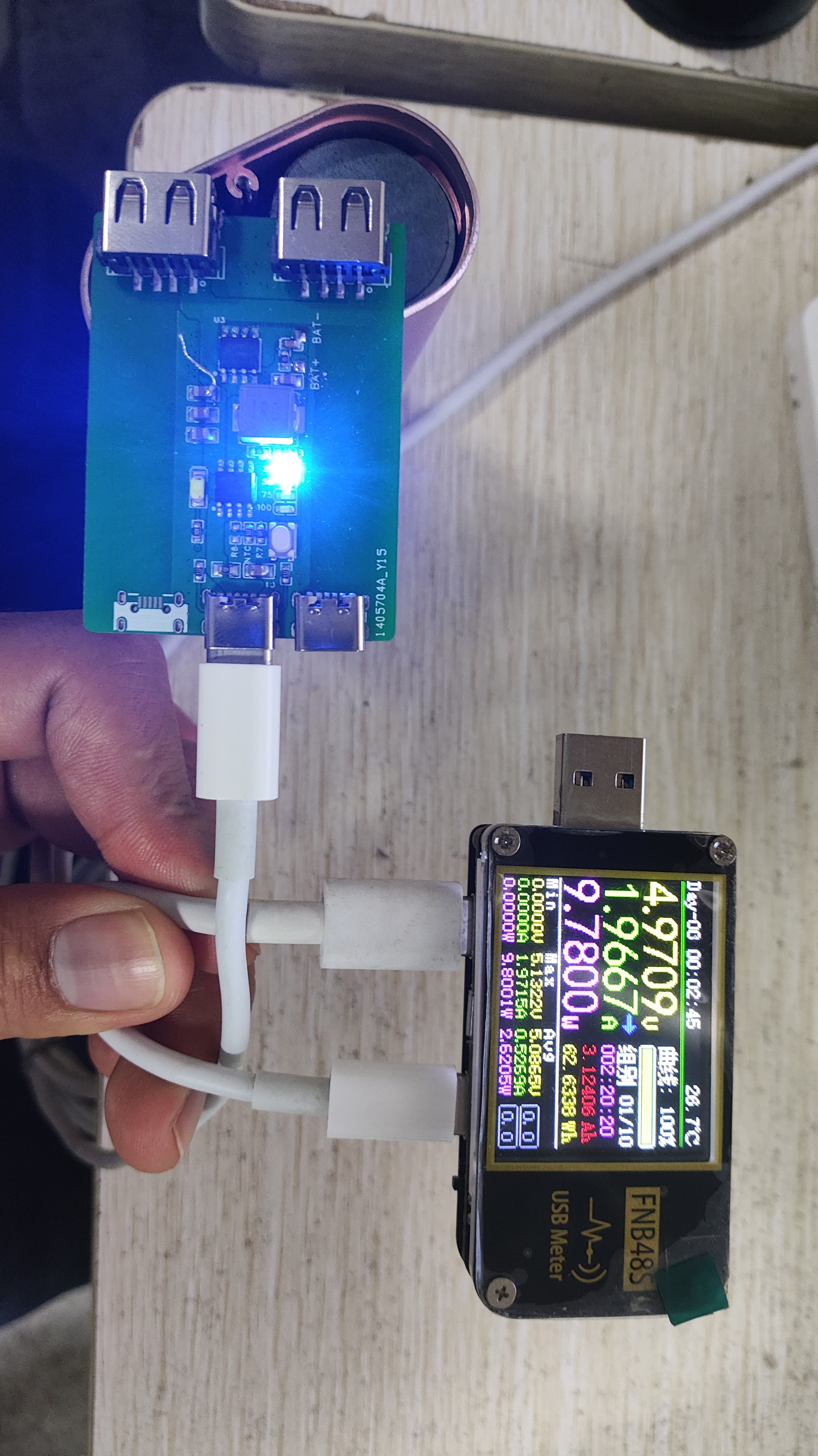
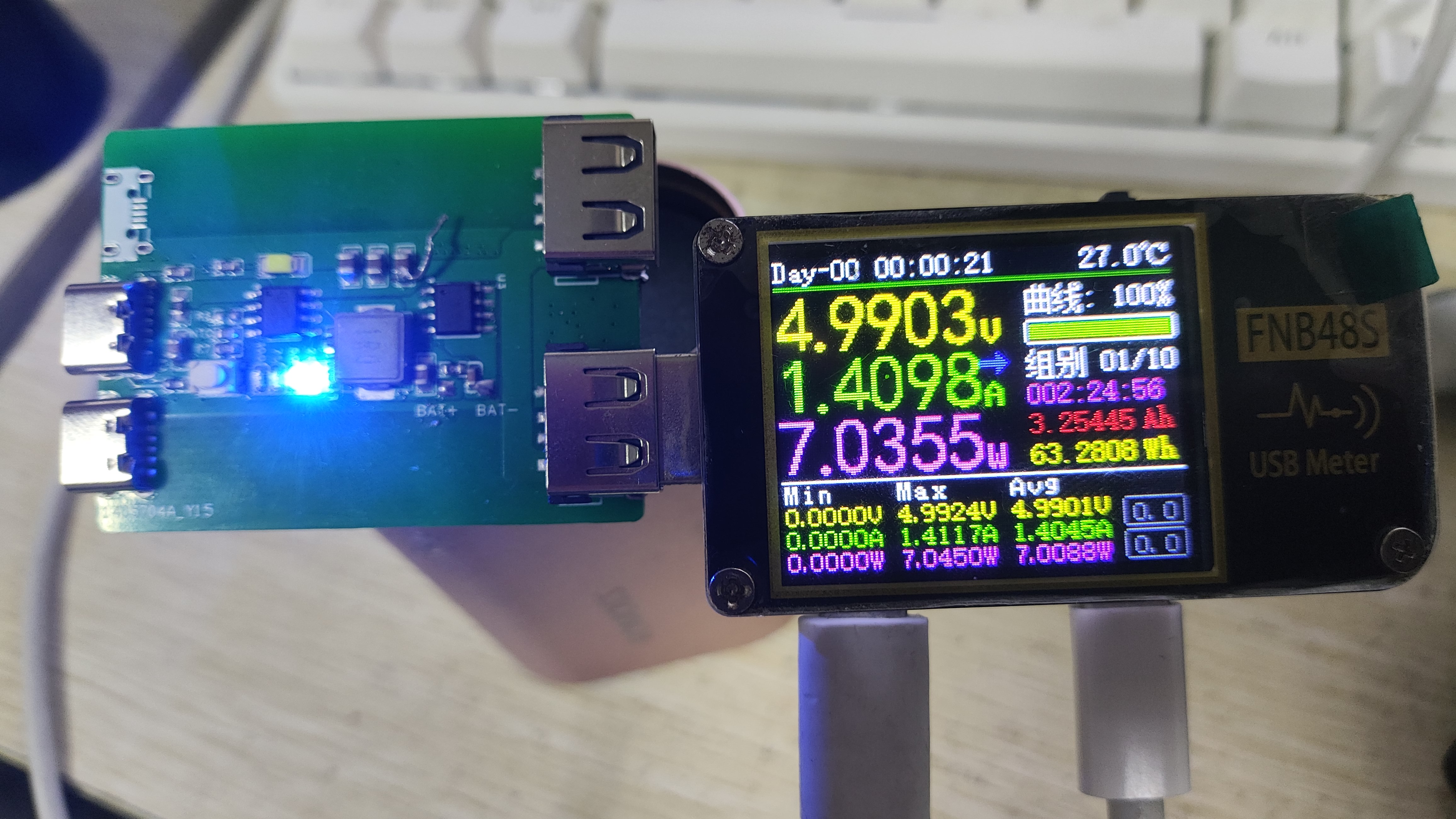
IP5407 charging module
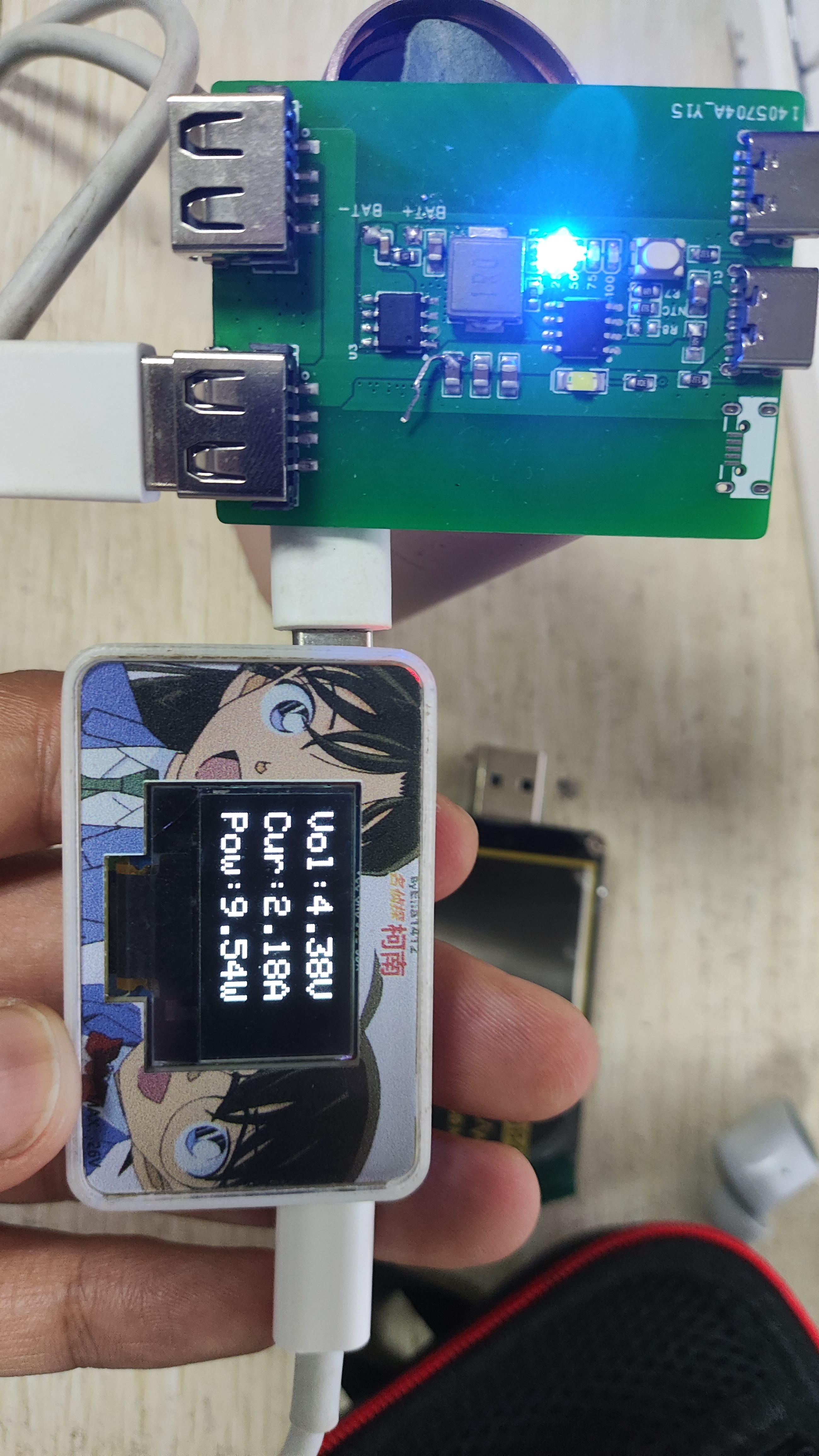
The appearance is for testing purposes only. It features a 2A charging and 2.1A/2.4A discharging integrated DCP function power bank SOC with IP3005A single lithium battery protection.
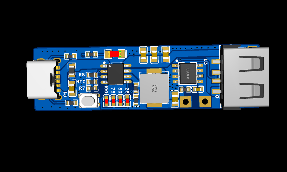
The IP5407 is a multi-functional power management SOC integrating a boost converter, lithium battery charging management, and battery level indicator, providing a complete power solution for power banks. Features
include: 2.1A/2.4A synchronous boost conversion, 2.0A synchronous switching charging; boost efficiency up to 93%; charging efficiency up to 91%; built-in power path management supporting simultaneous charging and discharging; output supports 60mV line compensation
under no-load

and loaded conditions ;

protocol detection for
charging
and discharging.
A slight inductor hissing sound occurs when connecting to the first detector (consider replacing with an inductor with a larger saturation current). The charging device is an iPad.
PDF_IP5407 charging module.zip
Altium_IP5407 charging module.zip
PADS_IP5407 charging module.zip
BOM_IP5407 charging module.xlsx
97250
CH340N Serial Port Tool
USB to TTL serial port CH340N module
Based on CH340N, with 3.3V and 5V TTL level switching.
PDF_CH340N Serial Port Tool.zip
Altium_CH340N serial port tool.zip
PADS_CH340N Serial Port Tool.zip
BOM_CH340N Serial Port Tool.xlsx
97252
USB 2.0 docking station
DIY USB 2.0 docking station
This is a homemade USB 2.0 docking station using an SL2.1A controller and a hub chip. Speeds reach standard USB 2.0 speeds, with read speeds around 40MB/s and write speeds around 30MB/s (when all four USB ports are plugged in).
Performance is stable.
PDF_Dock USB2.0.zip
Altium_Dock USB2.0.zip
PADS_Dock USB2.0.zip
BOM_Extension Dock USB2.0.xlsx
97253
RoboMaster fluorescent charging module
RoboMaster fluorescent charging module, fully compatible with official specifications.
RoboMaster fluorescent charging module, compatible with official specifications. Heat dissipation: If mounted on a CNC-machined metal part, a heat sink is not required; if mounted on a 3D-printed part, a heat sink is necessary. Please purchase or customize the heat sink yourself to ensure good heat dissipation for the light board.

PDF_RoboMaster Fluorescence Charging Module.zip
Altium_RoboMaster fluorescent charging module.zip
PADS_RoboMaster fluorescence charging module.zip
BOM_RoboMaster Fluorescence Charging Module.xlsx
97254
USB to 4-port serial TTL downloader with no cold start
USB to 4TTL downloader, cold start-free circuit
I. Product Introduction:
This USB-to-4-port serial programmer, built using CH344, has been tested and can download STC series microcontrollers, including the ESP32 microcontroller. For the ESP32 microcontroller, the factory mode of the official flash_download_tool allows simultaneous downloading to multiple devices.
II. Circuit Design
: The cold-start circuit uses a transistor and PMOS configuration. During programming, the RTS pin is pulled low, interrupting the 5V power supply for several hundred milliseconds. The circuit diagram uses 1uF pins (C1, C2, C3, C4), which is sufficient for programming STC microcontrollers. My actual prototype test circuit used 10uF, resulting in a longer 5V interruption time compared to 1uF.
III. Discussion
1. The programming interface can be modified according to your usage. If using 3.3V, add an AMS1117-3.3 to convert the power supply. CH344 supports 3.3V and 5V.
2. Programming ESP32 requires grounding GPIO00 to put the module in download mode. To ensure compatibility with STC microcontrollers, I did not directly implement the GPIO00 pin pull-down circuit on the programmer. You can modify it as needed.
3. The CH344's CFG pin, the manual says, can be set to enable or disable flow control. I have reserved the interface, but I don't know the specific usage. It seems there's no difference between CFG being grounded and floating. Discussion on the usage of CFG is welcome.
PDF_USB to 4-port Serial TTL Downloader - Cold Start-Free.zip
Altium_USB to 4-port Serial TTL Downloader - Cold Start-Free.zip
PADS_USB to 4-port Serial TTL Downloader - Cold Start-Free.zip
BOM_USB to 4-port Serial TTL Downloader - Cold Start-Free.xlsx
97257
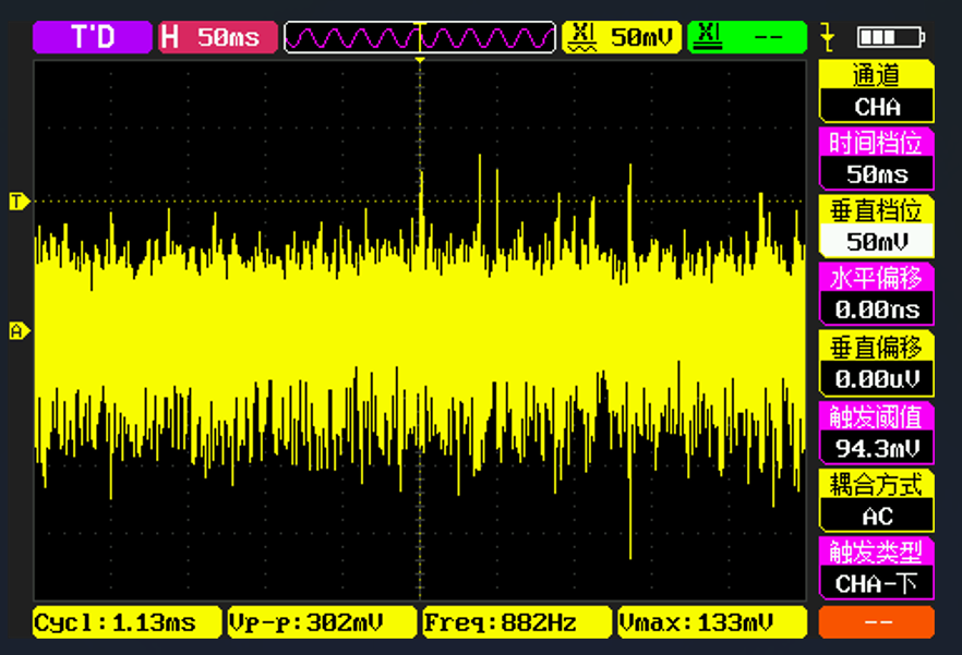
Digital oscilloscope
Instrumentation Training Questions
This project utilizes analog circuit components such as resistor dividers, operational amplifiers, and comparators to implement signal conditioning, amplification, shifting, filtering, and comparison functions to adapt to the input and output range of the STM32H750's ADC and DAC, thus realizing the oscilloscope's sampling and output functions. It also uses switches and voltage divider networks to implement the segmentation function of analog input and output channels, improving the measurement accuracy and output resolution of small signals. Furthermore, it utilizes the STM32H750's timer function to implement triggering and frequency measurement functions.
Project Functions: This project can function as a dual-channel oscilloscope, measuring analog signals within a ±15V range and converting them into digital signals within a 0-3.3V range for sampling by the STM32H750's ADC. It can also function as a single-channel signal source, outputting analog signals within a ±10V range, which are then generated by the STM32H750's DAC. It can also square-wave the input signal and utilize comparators and timers to implement triggering and frequency measurement functions.
PDF_DigitalOscilloscope.zip
Altium Digital Oscilloscope.zip
PADS_DigitalOscilloscope.zip
BOM_DigitalOscilloscope.xlsx
97258
electronic


 京公网安备 11010802033920号

 SMF104FL


