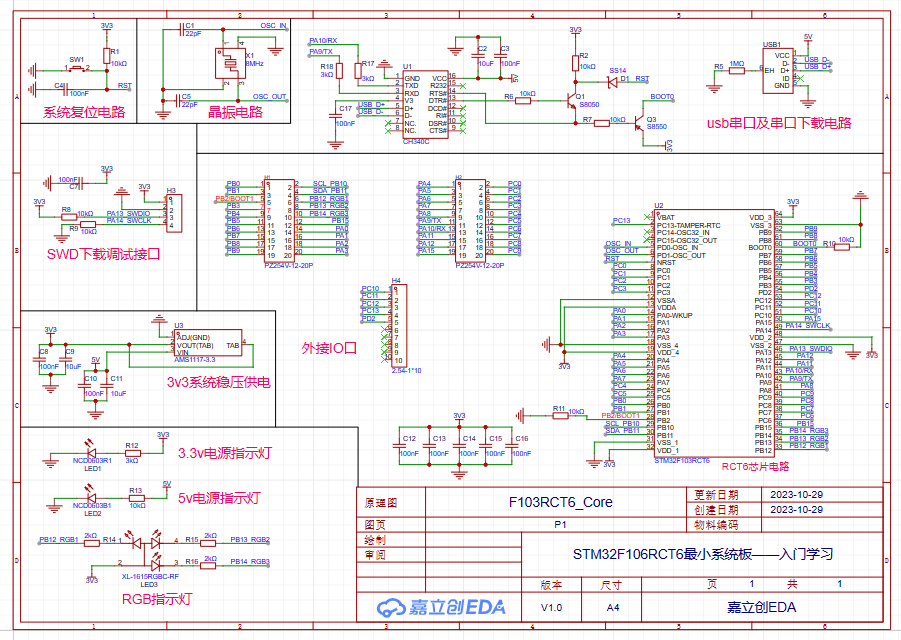
The STM32F106RCT6 minimum system board
is used for beginners to learn how to build small system circuits using STM32 and to learn soldering techniques.

QQ Video 20231029050642.mp4
rct6 program.zip
ProProject_STM32F106RCT6 Minimum System Board - Introductory Learning_2023-10-30.epro
PDF_STM32F106RCT6 Minimum System Board - Introductory Learning.zip
Altium_STM32F106RCT6 Minimum System Board - Introductory Learning.zip
PADS_STM32F106RCT6 Minimum System Board - Introductory Learning.zip
BOM_STM32F106RCT6 Minimum System Board - Introductory Learning.xlsx
97385
esp01s-wled
I happened to have an idle ESP01s on hand, so I drew a small baseboard based on the work of an open-source developer to play with RGB.
Ready-made RGB controllers are too expensive; this will only cost a few dollars to buy the components.
The LED strip is powered directly by a Type-C connector, so pay attention to the input voltage.
It will still generate heat, so consider adding heatsinks for prolonged use or if there are many LEDs.
Reference link: https://oshwhub.com/willxu2001/esp01s_wled
PDF_esp01s-wled.zip
Altium_esp01s-wled.zip
PADS_esp01s-wled.zip
BOM_esp01s-wled.xlsx
97386
ESP8266TEST
This development board, based on the ESP8266, is an intermediate product of a smoke alarm project. It can be connected to a TFT screen to function as a network clock.
The ESP8266 development board
uses the CP2102 to implement the ESP8266 automatic download circuit.
WeChat_20231030225712.mp4
1.4.2 SD3 PLUS Optimization.zip
PDF_ESP8266TEST.zip
Altium_ESP8266TEST.zip
PADS_ESP8266TEST.zip
BOM_ESP8266TEST.xlsx
97387
9LED Looping Puzzle Machine
A puzzle toy consisting of 9 LEDs that cycle through the display; pressing a button will randomly stop it on one of the LEDs.

This is my first self-designed PCB, based on the schematic from "100 Breadboard Examples." Soldering and powering it on the first try were successful. Materials were sourced from the "100 Breadboard Examples" kit, along with free PCB fabrication from LCSC EDA. The only additional cost was four batteries. This board still has some issues, as follows:
1. The board lacked rounded corners, which I just corrected.
2. The button placement is incorrect; it should be touch-sensitive.
3. The component layout is slightly off; they should be placed to one side so the side without components can accommodate the touch-sensitive buttons.
4. The capacitors and resistors were haphazardly placed, resulting in an incorrect 3D model; they appear to be surface-mount.
5. The battery compartment was selected as 2-cell instead of 4-cell, requiring a slightly larger board.
6. Other issues to be discovered...
A second version will be released after revisions .
WeChat_20231030230617.mp4
PDF_9LED Looping Puzzle Player.zip
Altium_9LED Loop Puzzle Player.zip
PADS_9LED Looping Puzzle Player.zip
BOM_9LED Looping Puzzle Player.xlsx
97388
1C1A desktop charger based on IP6520 and IP6505 standards
A desktop charger with 1C1A based on IP6520 and IP6505 standards, DC input 7.1V-32V, recommended 13V-24V, and adaptive input polarity (positive or negative).
The IP6520
is a step-down converter with integrated synchronous switching, supporting multiple fast charging protocols, Type-C output, and USB PD2.0/PD3.0 (PPS) protocols. It provides a complete solution for car chargers, fast charging adapters, and smart power strips. The IP6520 has a built-in power MOSFET, an input voltage range of 7.1V to 32V, and an output voltage range of 3V to 12V, providing a maximum output power of 25W. It automatically adjusts the output voltage and current according to the detected fast charging protocol. Typical output voltages and currents are: 5V/3A, 9V/2.5A, and 12V/2A. The IP6520's PD output has CV/CC characteristics. When the output current is less than the set value, it outputs in CV mode with a constant output voltage; when the output current is greater than the set value, it outputs in CC mode with a reduced output voltage. The IP6520 has an automatic overcurrent point adjustment function, supporting a maximum output of 10V/2.5A after a successful high-voltage SCP and fast charging protocol handshake. When the device connected to the IP6520's Type-C interface supports high-voltage SCP, it prioritizes outputting high-voltage SCP, resulting in higher charging power compared to PD output. The IP6520's output voltage features line compensation; as the output current increases, the output voltage increases accordingly to compensate for voltage drops caused by connection line impedance. The IP6520 has a soft-start function to prevent inrush current from affecting the stability of the input power supply. The IP6520 supports Type-C interface output and integrates various fast charging protocols. It can automatically identify the fast charging protocol supported by the connected device via CC1/CC2 or DP/DM, and then automatically adjust the output voltage and current. Supported fast charging protocols include: DCP (Apple and BC1.2), Qualcomm QC2.0/QC3.0 (class A), Huawei fast charging protocols FCP and HVSCP, Samsung fast charging protocol AFC (MAX 12V), and USB PD2.0/PD3.0 (PPS) output protocols. The IP6520 offers multiple protection functions, including input overvoltage and undervoltage protection, and output overcurrent, overvoltage, undervoltage, and short-circuit protection.
It is packaged in an ESOP-8 package and
supports DCP/QC2.0/QC3.0/FCP/HVSCP/AFC/MTK PE/PD3.0/PPS with a maximum power output of 25W. The IP6505 is an integrated synchronous switch buck converter supporting 11 fast charging protocols, providing a complete solution for car chargers, fast charging adapters, and smart power strips.
It features
a built-in power MOSFET, an input voltage range of 4.5V to 32V, an output voltage range of 3V to 12V, and a maximum output power of 24W. It automatically adjusts the output voltage and current based on the detected fast charging protocol. Typical output voltages and currents are: 4V@3.6A, 5V@3.4A, 7V@3A, 9V@2.5A, and 12V@2A. The IP6505 boasts a buck conversion efficiency of up to 97%. Its output features CV/CC characteristics: when the output current is less than a set value, it operates in CV mode with a constant output voltage; when the output current exceeds the set value, it operates in CC mode with a reduced output voltage. The IP6505's output voltage includes line compensation; as the output current increases, the output voltage increases accordingly to compensate for voltage drops caused by connection impedance. The IP6505 features soft-start functionality to prevent inrush current from affecting the stability of the input power supply. It integrates various fast charging protocols and can automatically identify the fast charging protocols supported by the connected device via DP/DM, then automatically adjust the output voltage and current. Supported fast charging protocols include: DCP (Apple, Samsung, and BC1.2), Qualcomm QC2.0/QC3.0 (class A), MTK PE1.1/2.0, Huawei FCP/SCP, Samsung AFC, and Spreadtrum SFCP. The IP6505 offers multiple protection functions, including input overvoltage and undervoltage protection, and output overcurrent, overvoltage, undervoltage, and short-circuit protection.
The IP6505 uses an ESOP-8 package.
It supports DCP/QC2.0/QC3.0/MTK PE1.1/PE2.0/FCP/SCP/AFC/SFCP with a maximum power of 24W.
For this project
, PCB1 will be made of FR-4 material, and PCB2 (empty board) will be made of aluminum substrate. A frosted acrylic panel is recommended.
You will need 4 M2 screws (5mm long), 4 M2 double-ended knurled screw posts (11mm long), 8 M2 single-ended knurled screw posts (3mm thread, 3mm body), and one 3.5mm thick thermal pad.
Installation instructions are omitted here.
IMG_20231029_141620.jpg
IP6505_datasheet.pdf
IP6520_datasheet.PDF
PDF_1C1A Desktop Charger Based on IP6520 and IP6505 Solutions.zip
Altium 1C1A Desktop Charger Based on IP6520 and IP6505 Standards.zip
PADS 1C1A Desktop Charger Based on IP6520 and IP6505 Standards.zip
BOM_1C1A Desktop Charger Based on IP6520 and IP6505 Standards.xlsx
97389
AIR001 Batch Programmer
The programmer based on the Hezhou AIR001 MCU has been verified to run normally.
It's essentially a simplified version of the air001 development board, making the chip pluggable and removing other unnecessary peripheral modules.
You'll need to purchase a TSSOP20 programming socket. After soldering, directly program the test firmware. If the red light starts flashing, it's basically working correctly.
test_led.ino
PDF_AIR001 Batch Burner.zip
Altium_AIR001 Batch Programmer.zip
PADS_AIR001 Batch Programmer.zip
BOM_AIR001 Batch Programmer.xlsx
97392
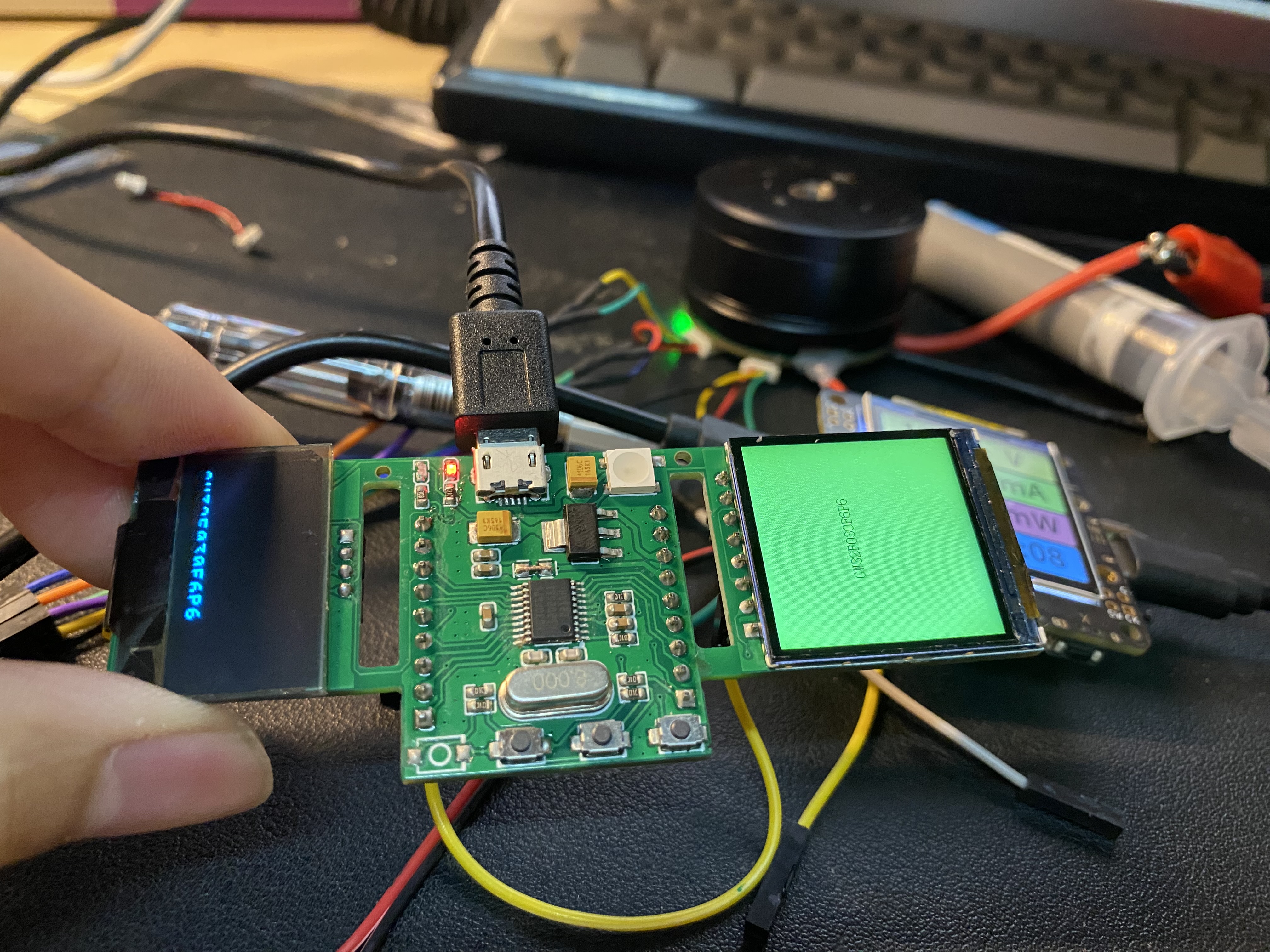
The CW32F030F6P6 is a minimum system with a 0.96-inch OLED and a 1.4-inch LCD.
The CW32F6P6 is a minimal system with a 0.96-inch OLED and a 1.4-inch LCD, both purchased from Lao Wang's store on Taobao.
IMG_5100.mp4
PDF_cw32f030f6p6 Minimal System with 0.96-inch OLED and 1.4-inch LCD.zip
Altium_cw32f030f6p6 minimum system with 0.96-inch OLED and 1.4-inch LCD.zip
PADS_cw32f030f6p6 minimum system, with 0.96-inch OLED and 1.4-inch LCD.zip
BOM_cw32f030f6p6 minimum system, with 0.96-inch OLED and 1.4-inch LCD.xlsx
97393
Low cost, 5-inch portable touchscreen with HDMI resolution of 485x840, button control, and lighting effects.
Low cost, 5-inch portable screen with touch HDMI, 485x840 resolution, button control, and lighting effects.
1. Demo video: https://www.bilibili.com/video/BV1eH4y1Q7CA/?spm_id_from=333.999.0.0
2. Actual effect:
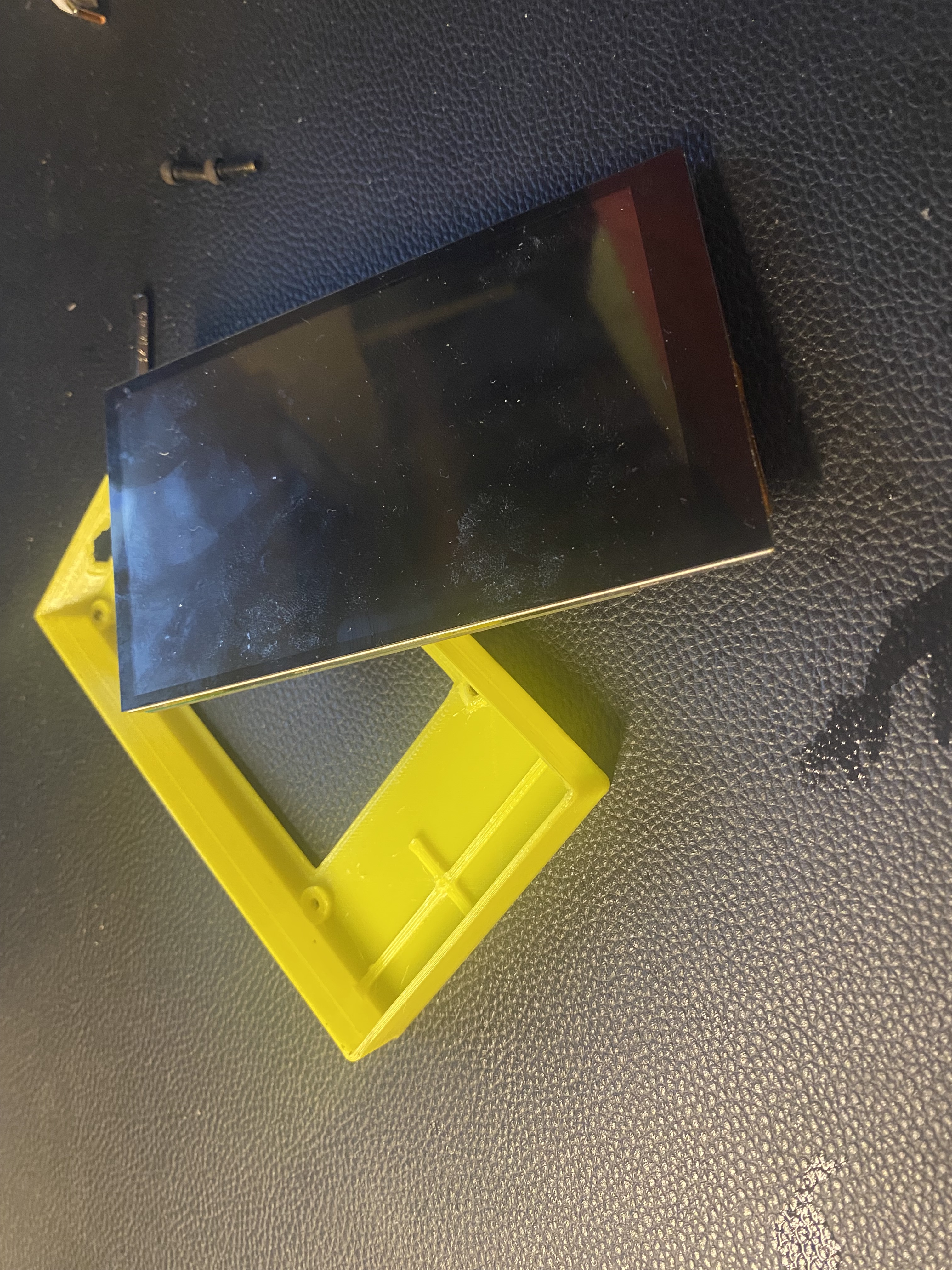
3. I'm not very good at drawing the shell, so it just covers the screen. I've open-sourced the project, so everyone can modify it themselves.
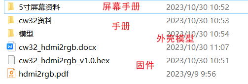
4. Open source materials
5. Also open source a minimal F6P6 system with OLED and a 1.4-inch LCD screen.
I. Hardware Overview
1. Power supply: 5V->3V3->1V8
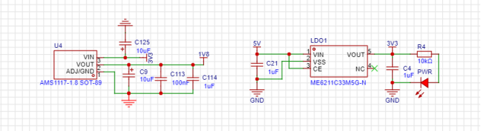
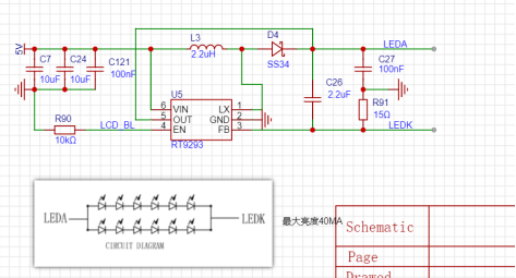
2. LCD backlight driver circuit
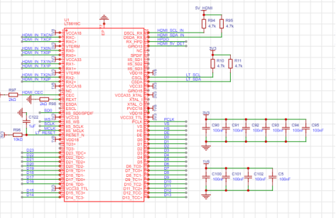
3. LTC8619C peripheral driver circuit
4. HPD insertion detection circuit

5. CW32 peripheral circuit

6. Button control circuit

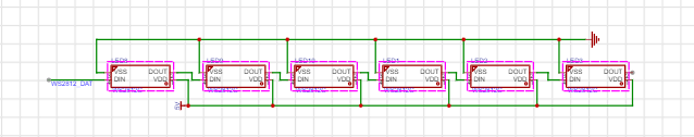
7. W2812 lighting control circuit
8. Ch554G touch to USB circuit
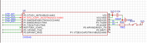
II. Software Overview
1. Consult the LCD driver, GT911, and LTC8619C datasheets to understand key communication timings, register configuration details, and register configuration methods. 2.
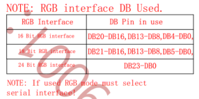
RGB working modes: RGB666, RGB888, etc. The LTC8619C and LCD configurations must be identical; different modes have different pins. Carefully check the datasheets before hardware design.
3. LTC8619C EDID parameter configuration involves using EDID configuration tools and EDID reading software to configure various parameters suitable for driving the LCD, such as clock frequency, RGB timing, I2S audio configuration,
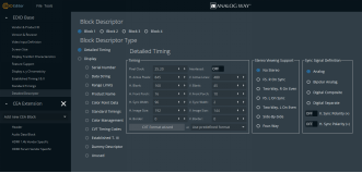
etc.
Open source materials.rar
PDF_Low-cost, 5-inch portable touchscreen with HDMI HDMI display, 485x840 resolution, button controls, lighting effects.zip
Altium - Low-cost, 5-inch portable touchscreen with HDMI output, 485x840 resolution, button controls, lighting effects.zip
PADS - Low-cost, 5-inch portable touchscreen with HDMI display, 485x840 resolution, button control, lighting effects.zip
BOM: Low cost, 5-inch portable touchscreen HDMI display, 485x840 resolution, button controls, lighting effects.xlsx
97394
ESP32-C3 displays weather, time, and class schedule; 0.96-inch OLED screen.
This project, based on the ESP32-C3 core board, displays the local weather, current time, and today's class schedule. It uses a 0.96-inch OLED IIC driver. The PCB is very small, easily fitting in a pocket, effectively solving the problem of having to take out a phone to check which class is being held before class.
The battery uses a 3.7V lithium battery. The connecting studs are 2.5mm in diameter, and three screws are used with lengths of 4mm and 10mm (depending on the battery size). The keycaps need to be of this type.

Front and rear panel CAD drawings and program source code links will be sent after someone comments.
PDF_esp32-c3 displays weather, time, and class schedules; 0.96-inch OLED.zip
Altium_esp32-c3 displays weather, time, and class schedule; 0.96-inch OLED.zip
PADS_esp32-c3 displays weather, time, and class schedule; 0.96-inch OLED.zip
BOM_esp32-c3 displays weather, time, and class schedule; 0.96-inch OLED.xlsx
97395
51 Heart-shaped Flowing Lights
Implementing a running light effect using a 51 microcontroller
A simple project for the school uses the numerous I/O ports of a 51 microcontroller to control LEDs, and a running light effect is achieved through programming.
QQ image 20231027220542.jpg
QQ Video 20231027220524.mp4
project.hex
PDF_51 Heart-Shaped Flowing Lights.zip
Altium_51 Heart-Shaped Flowing Light.zip
PADS_51 Heart-Shaped Flowing Light.zip
BOM_51 Heart-shaped Flowing Light.xlsx
97397
electronic


 京公网安备 11010802033920号

 1N6063ACOX.160


