I wrote a simple clock program using the internal RTC on an STC32 development board with an ST7735 screen!
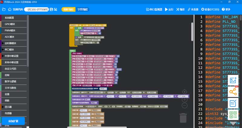
The program was developed using Tianwen Block graphical programming.

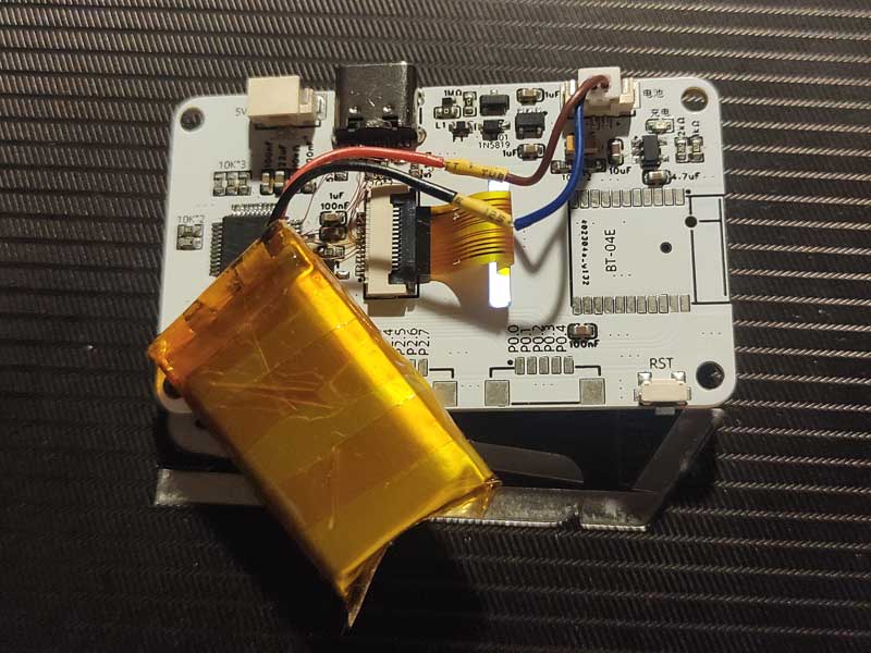
STC32G-ST7735RTC Clock.hd
studio_video_1722348584955.mp4
PDF_STC32G Development Board with 1.8-inch ST7735 Screen.zip
Altium_STC32G development board with 1.8-inch ST7735 screen.zip
PADS_STC32G development board with 1.8-inch ST7735 screen.zip
BOM_STC32G with 1.8-inch ST7735 screen development board.xlsx
93429
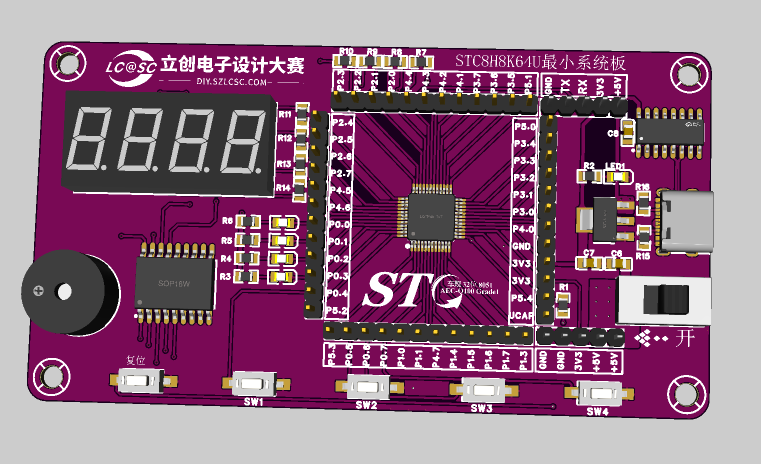
STC8H8K64U Minimum System Board (STC Microcontroller Creative Design Competition)
STC8H8K64U Minimum System Board
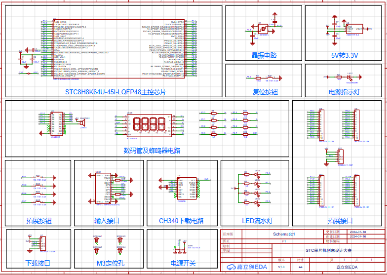
This design uses the STC8H8K64U-45I-LQFP48 main controller as the core of the development board.
Features include:
Core: • Ultra-high-speed 8051 core (1T), approximately 12 times faster than the traditional 8051, instruction code fully compatible with the traditional 8051 • 22 interrupt sources, 4 interrupt priority levels • Supports online simulation Operating Voltage: 1.9V~5.5V Operating Temperature: -40℃~85℃
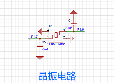
Main Control Circuit:

External crystal oscillator, reset, power indicator,
5V to 3.3V conversion, LDO linear regulator, expanding the microcontroller's power interface to power external modules

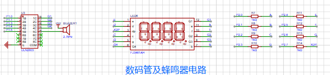
. The digital tube display section, running lights, and external expansion button circuit mainly use ULN2803 to drive the digital tube and an active buzzer, enriching the microcontroller's playability.

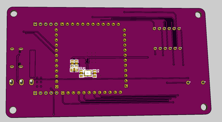
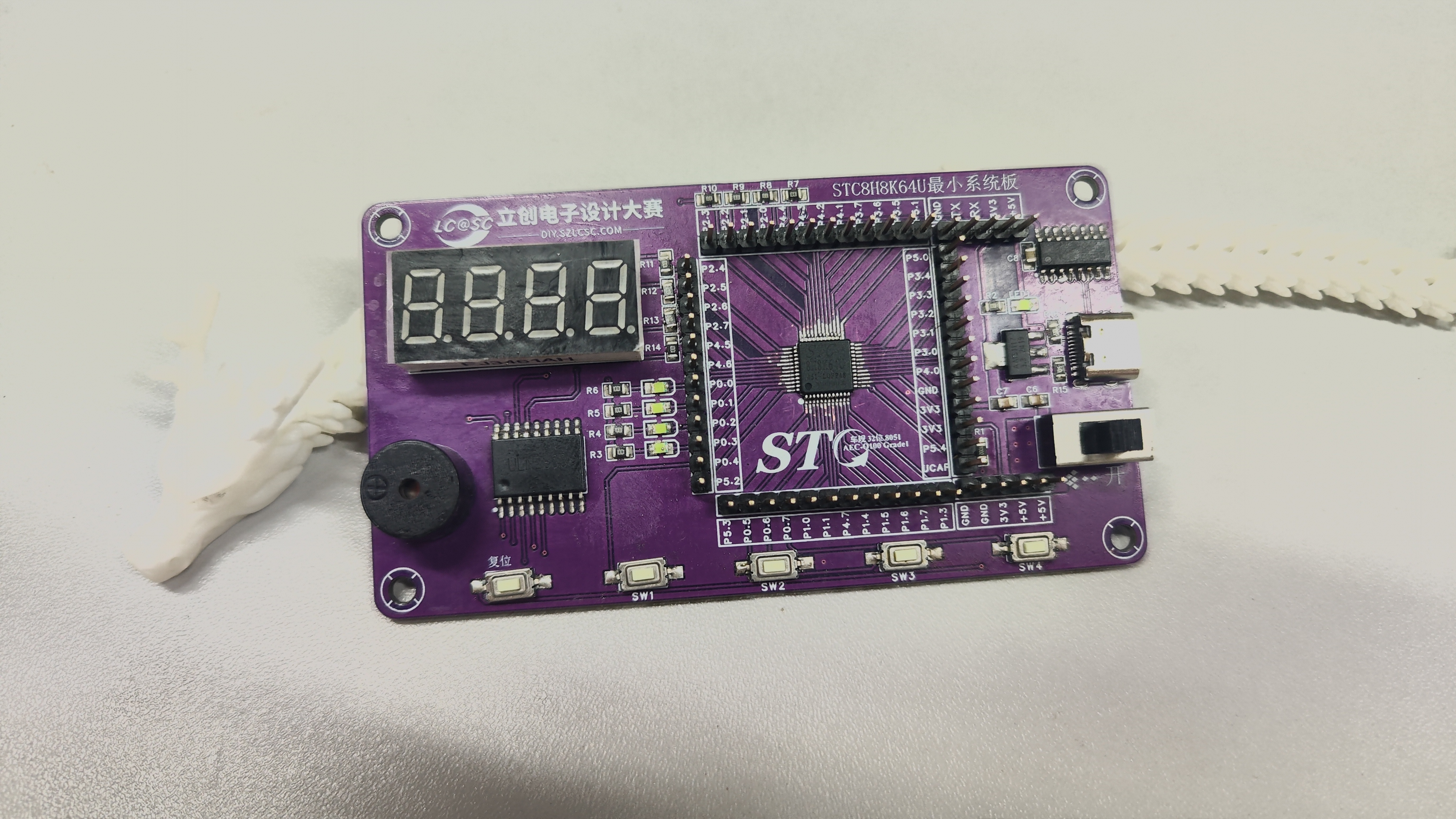
Power supply and download circuit (there should be three types of downloads here).
CH340 is a USB bus adapter chip, implementing USB to serial port or USB to printer port conversion. The CH340 is a domestically produced chip with a wide range of applications and a high market share. Other commonly used USB-to-serial chips include the CP2102, PL2303, and FT232, but the CH340 offers the best price-performance ratio. Connecting the CH340 to the on-chip UART of a microcontroller (MCU) via a serial converter enables one-click programming. The complete

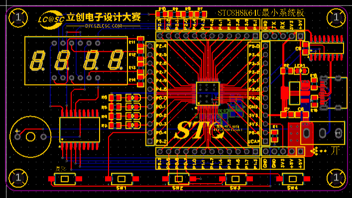
pinout schematic is attached (too blurry). The PCB layout is a bit ugly—but it works (just kidding!). A 3D preview of the PCB (the crystal oscillator is on the back—a little panicked!). The actual product is ready! The project is complete (I'm a newbie, so I need more practice) . Thanks to JLCPCB for the free coupon! A godsend for electronics enthusiasts! (Very loudly)


STC8H8K64U Minimum System Board.pdf
STC8H8K64U Minimum System Board.xlsx
STC8H8K64U Minimum System Board.zip
PDF_STC8H8K64U Minimum System Board (STC Microcontroller Creative Design Competition).zip
Altium_STC8H8K64U Minimum System Board (STC Microcontroller Creative Design Competition).zip
PADS_STC8H8K64U Minimum System Board (STC Microcontroller Creative Design Competition).zip
BOM_STC8H8K64U Minimum System Board (STC Microcontroller Creative Design Competition).xlsx
93430
RGB controller
The RGB lighting can be adjusted via Bluetooth on a mobile phone and serial port on a PC, allowing users to customize preset RGB effects, colors, and brightness without programming. It also features an external microphone for creating rhythmic effects.
I. Function Introduction:
The WS2812 RGB LED can be adjusted via Bluetooth from a mobile phone and serial port from a PC, allowing users to customize preset RGB effects, colors, and brightness without programming. It also includes an external microphone for rhythmic effects.
II. Overall Design Scheme
: This design uses the STC32G12K128 chip as the MCU. Bluetooth communication is achieved using a ZX-D30 Bluetooth module. Reserved PC serial and Bluetooth serial ports allow for upper-level computer and APK development.
III. Hardware Introduction:
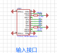
3.1 Power Input
: Power is a crucial component of the circuit. This project uses both Type-C and external DC power. Power can be switched via the SW1 switch when Type-C power is insufficient.

3.2 Wireless Communication :
Wireless communication is achieved using the ZX-D30 Bluetooth module.

3.3 Other:
A reserved microphone interface allows for rhythmic effects.

IV. Programming:
The program is burned using an STC-ISP with a running frequency of 24MHz. The burning file is attached.

V. Physical Demonstration:
A video demonstration is published on the Bilibili video platform.
Link: https://www.bilibili.com/video/BV1yE421w73Q
BV ID: BV1yE421w73Q
RGB controller.zip
PDF_RGB controller.zip
Altium_RGB controller.zip
PADS_RGB controller.zip
BOM_RGB controller.xlsx
93431
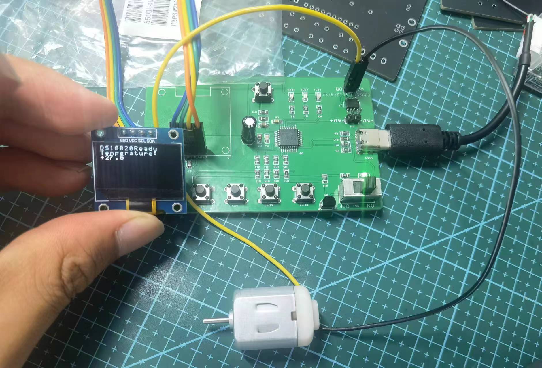
51 Smart Mini Fan
This smart fan uses the STC8H8K64U as the main control chip and the DS18B20 as the temperature sensor. It measures the current temperature using the temperature sensor, adjusts the fan speed in real time, and displays the data on an OLED screen.
I. Team Introduction:
wzp100 is responsible for PCB fabrication and programming;
sunwu2004 is responsible for PCB schematic design and soldering.
II. Design Goal:
A smart fan using an STC8H8K64U as the main control chip and a DS18B20 as the temperature sensor. The fan measures the current temperature, adjusts the fan speed, and displays the data in real-time on an OLED screen.
III. Design Summary:
PCB design and soldering
; code writing, burning, and debugging.
IV. Design Analysis:
The STC8H8K64U main control chip integrates circuits such as the crystal oscillator, which originally required external design, greatly simplifying the circuit design.
V. Overall Design Block
Diagram: TD
reset --> Sensor acquires temperature --> Displays current temperature and fan speed --> Adjusts fan speed --> Sensor acquires temperature.
VI. Hardware Circuit Composition
: Detailed description of each circuit component in the project, along with analysis of the circuit schematic. If using a pre-built module board, please indicate that it is open source.
Hardware Components : Main
Control Chip: STC8H8K64U
integrated crystal oscillator, simplifying design;
Temperature Sensor: DS18B20
high-precision temperature acquisition;
Display Module: OLED screen
for real-time temperature and fan speed display
; Fan Drive Circuit:
Fan speed control
circuit schematic analysis ;
Power Management Circuit:
Provides stable power to each module
; Main Control Circuit
: STC8H8K64U main control chip and its peripheral circuits;
Sensor Interface Circuit :
DS18B20 connection and data acquisition circuit;
Display Circuit:
OLED screen connection and drive
circuit; Fan Control Circuit:
Fan drive and speed control circuit .
VII. Program Flowchart
: TD
Start --> Initialization --> Read Temperature --> Display Temperature and Speed --> Determine Temperature Range --> Adjust Fan Speed --> Temperature reading
program flow
initialization
Initialize each module
Initialize temperature
Read current temperature via DS18B20
Display temperature and fan speed
Display temperature and fan speed on OLED screen
Determine temperature range Adjust
fan speed according to temperature Adjust fan speed VIII. Physical demonstration IX. Precautions Soldering precautions Ensure solder joints are strong and avoid cold solder joints Power management Ensure stable power supply and avoid voltage fluctuations X. Demonstration video see attachment XI. Attachment contents Attachment 1: Demonstration video Attachment 2: Program code

Demo video.mp4
Program code.zip
PDF_51 Smart Mini Fan.zip
Altium_51 Smart Mini Fan.zip
PADS_51 Smart Mini Fan.zip
BOM_51 Smart Mini Fan.xlsx
93432
Color Screen Knob - ESP32S3-HUB-V1
The ESP32S3 N8R2 features an encoder knob with a 1.28-inch screen.
Main controller: ESP32S3 N8R8 (a module with PSRAM is recommended; otherwise, GIF playback may be impossible).
Screen: 1.28-inch 240*240 GC9A01 LCD.
Encoder: EC35 hollow encoder (an encoder kit with a matching knob housing is recommended).
Hub: SL2.1A, used to connect the USB ports of the ES32S3 and CH340C, and also to power the CH340C.
LDO: ME6214C33M5G (maximum power supply current of 300mA may not support WiFi; replacing it with AP2112K33TRG will slightly increase power consumption, but can provide a maximum current of 600mA; both are pin-2-pin).
Charging: LR4054-T (TP4054 can also be used as a substitute; it is a pin-2-pin).
Battery: 900mAh soft-pack battery, 28*30mm in size and 9mm thick.
Standby: With WiFi disabled, BLE enabled, and CPU frequency at 240MHz, the ESP32S3 can operate continuously for 8 hours. Entering DeepSleep + GPIO wake-up mode results in a 10% power consumption per month, and theoretically, it can last for over 6 months on a full charge.
Development Environment: IDF4.4. Test code will be attached after being organized.
Replica Discussion: Group 531774127. Please specify the project you are replicating in your group nickname after joining.
Attachment Description:
1. lvgl_1_28_base(idf4.4).zip: Source code based on VSCode + IDF4.4. After decompression, follow the instructions in the main() function within the source code. The program includes the BLE HID and USB HID functions implemented in the video; both BLE and USB functions are enabled by default.
2. Shell STL file.zip: 3D printing file for the shell, which can be directly printed using 3D Monkey.
3. Gerber_PCB_Color Screen Knob-Screen Base Plate-12P.zip: Screen base plate. It connects to the ESP32S3 control board via a 12-pin 0.5mm pitch FPC cable.
Demo functions:
After 60 seconds of inactivity, it enters sleep mode; pressing the screen wakes it up.
After waking, the battery percentage is displayed at the bottom edge of the screen. Bluetooth can also search for ESP BLE_HID2 devices.
Pressing and holding the screen for 2 seconds and then rotating the knob switches between GIFs; pressing and holding again exits the GIF selection.
Rotating the knob: adjusts the volume; pressing + rotating the knob: skip to the previous/next track; double-click: mute; single-click: pause.
Modification notes:
2024/6/17: Fixed the issue of the LED indicator not lighting up in the LR4054-T charging circuit (the schematic diagram on the first page of the PDF datasheet provided by LCSC for LR4054-T, part number C5336483, is incorrect). The CHRG pin of the LR4054-T should be connected to the cathode of the LED pin, and the LED anode should be connected to the VBUS pin of the Type-C port.
ESP-KNOB(1).jpg
ESP-KNOB.mp4
Shell STL file.zip
GIF switching demonstration.mp4
HID feature demonstration.mp4
Gerber_PCB_Color Screen Knob-Screen Base Plate-12P.zip
lvgl_1_28_base.zip
PDF_Color Screen Knob-ESP32S3-HUB-V1.zip
Altium_Color Screen Knob-ESP32S3-HUB-V1.zip
PADS_Color Screen Knob-ESP32S3-HUB-V1.zip
BOM_Color Screen Knob-ESP32S3-HUB-V1.xlsx
93434
STC32G12K128 Development Board
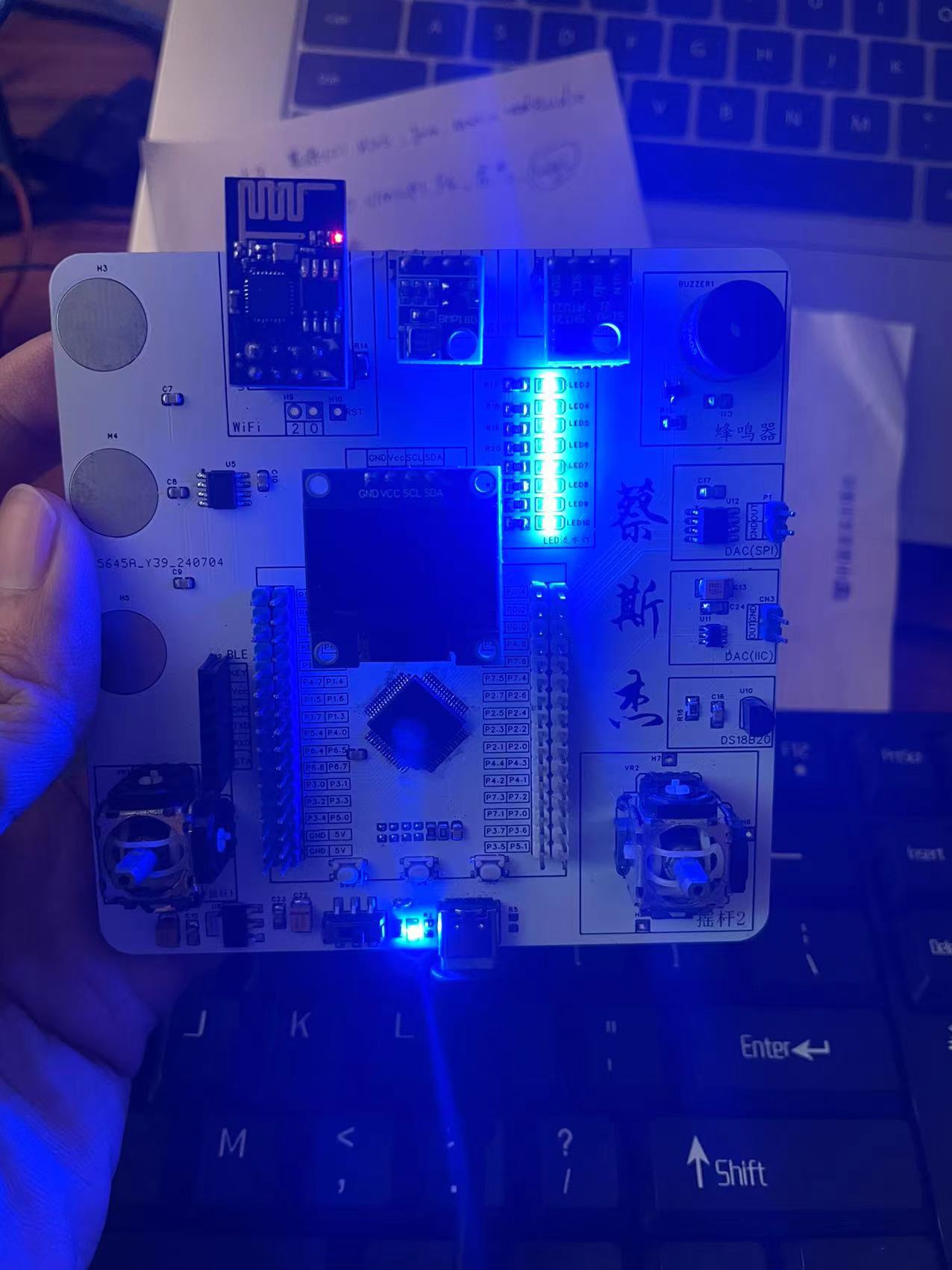
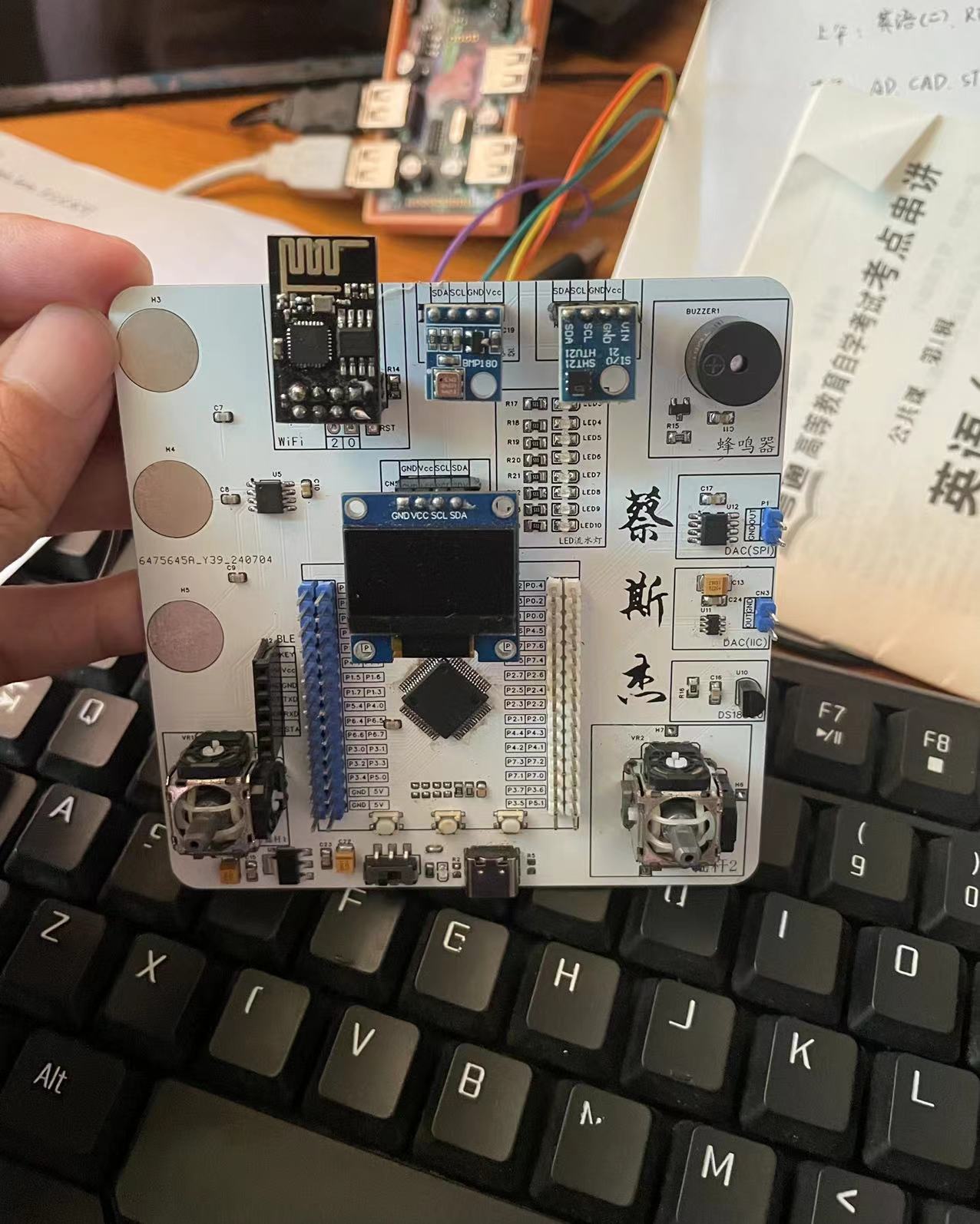
The main controller is the STC32G12K128. The STC32G12K128 microcontroller development board integrates IoT, Bluetooth, SPI (DAC), IIC (DAC), touch buttons, buzzer, barometric pressure sensor, temperature and humidity sensor (SHT21), joystick and other functions.
I. Development Board Introduction
1. The main controller uses the STC32G12K128 32-bit processor chip from STC, which is capable of running FreeRTOS.
2. This development board is designed for beginners to implement OLED display, ESP-01s IoT, HC08 Bluetooth communication, BMP180 barometric pressure sensor, SHT21 temperature and humidity sensor, and DAC conversion circuits for both SPI and IIC communication.
II. Physical Demonstration
e9fe9bf3ebf186551bf012a38d7983d4.mp4
PDF_STC32G12K128 development board.zip
Altium_STC32G12K128 development board.zip
PADS_STC32G12K128 development board.zip
BOM_STC32G12K128 development board.xlsx
93435
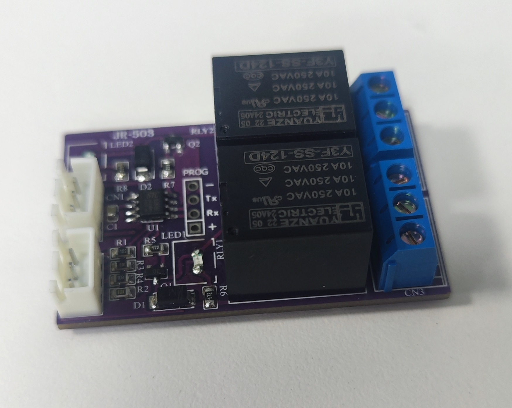
Two-way relay switch module
A two-channel relay module controlled by a 51 microcontroller, which can be flexibly controlled by modifying the program according to individual needs.
This project
uses two buttons, two relays, and a 51 microcontroller to control two lights on/off. The STC microcontroller, relays, buttons, and other materials are readily available, and the
circuit
is easy to build, making it a simple project for beginners to quickly replicate. Once completed, the project can be used to control lights on/off, motors start/stop, etc.
Notes: Overall design scheme block diagram,
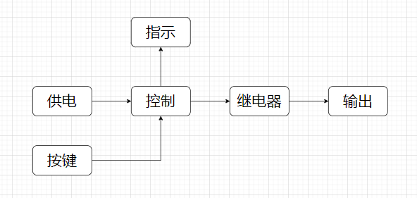
schematic diagram, design description.
Note: Describe the design schematic diagram of each module in the project. Schematic diagrams are required, and ideally, physical photos should also be included. Each module needs a description. If a module does not require design, please indicate the source of the design.
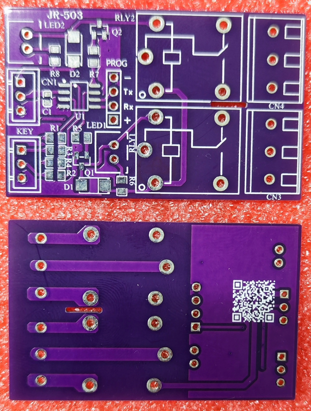
PCB Design
Notes: This section contains some PCB design notes, such as PCB layout, routing, trace width, spacing, and other design considerations.
Software
Notes: Software can be nested using code blocks. It's not necessary to explain all parts of the software; only the important parts need to be explained.
Code Block:
#include
void main()
{
printf(""\n);
}
Physical Demonstration
Notes:
Regarding relay selection, the relay voltage can be freely chosen, as long as it matches the power supply voltage. For example, if you choose a 5V relay, you only need one 5V power supply. If you choose a 12V relay, then you need one 12V power supply and one 5V power supply. I have a 24V relay on hand, so I chose a 24V relay for the module I soldered, hence the two power connectors on the board.
Demo Video
Instructions: Only upload attachments for the demo video. Attachments can only be 50MB in size. Files larger than 50MB can be hosted on other cloud storage services or video websites; simply include the link here.
Other Attachment Upload
Instructions: Entries participating in the event must upload all project-related program attachments to an open-source platform or personal code storage cloud. Attachments can be uploaded up to a maximum of 50MB (please do not upload to the LCSC workspace, as there are limitations).
2-way relay switch.jpg
Two-way relay switch module.hex
lv_7031358993746398475_20240730124344.mp4
PDF_Two-way relay switch module.zip
Altium Two-Way Relay Switch Module.zip
PADS_Two-way Relay Switch Module.zip
BOM_Two-way Relay Switch Module.xlsx
93436
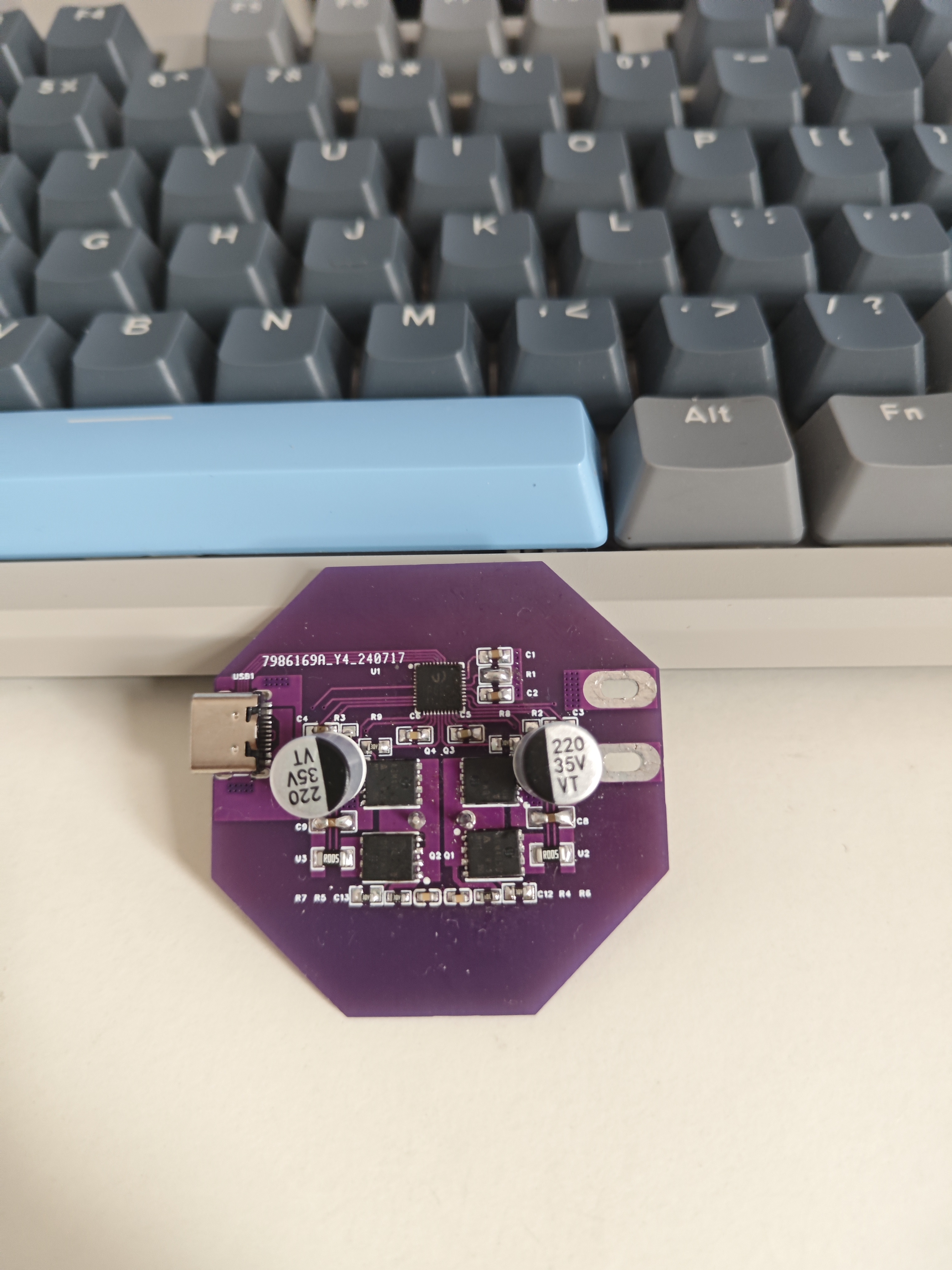
IP6557 Single C 140W Verification
Supports buck-boost converters for fast charging protocols such as UFCS/PD2.0/PD3.1/ERP28V.
Input voltage range: 5V-31V. Supports QC2.0/QC3.0/QC3+/QC4+/QC5/FCP/HSCP/AFC/MTK/UFCS, and USB-C interface PD3.1/PPS/ERP28V.
PDF_IP6557 Single C 140w Verification.zip
Altium_IP6557 Single C 140w Verification.zip
PADS_IP6557 Single C 140w Verification.zip
BOM_IP6557 Single C 140w Verification.xlsx
93437
electronic


 京公网安备 11010802033920号

 JANTX1N4110DURTR-1


