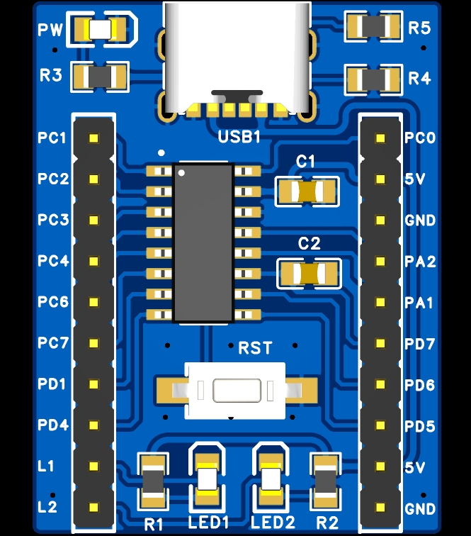
The CH32V003A4M6 minimum system board has been verified by LED activation. You can order the PCB directly. Components can also be purchased directly from LCSC's online store. CH32V003A4M6 can be purchased separately from Taobao.
STM32 Learning Board from the RobotIC Robotics Lab at South China University of Technology
Teaching using the STM32 learning board of the RobotIC Robotics Lab at South China University of Technology
with HAL library + CubeMX
The MAX78000FTHR expansion board facilitates image acquisition for the MAX78000FTHR.
November 17th Update - Edge AI Applications of the MAX78000FTHR:
In the previous content, I used the MAX78000FTHR development board and the expansion board in this project to implement a simple camera function, capable of taking pictures and saving them to an SD card.
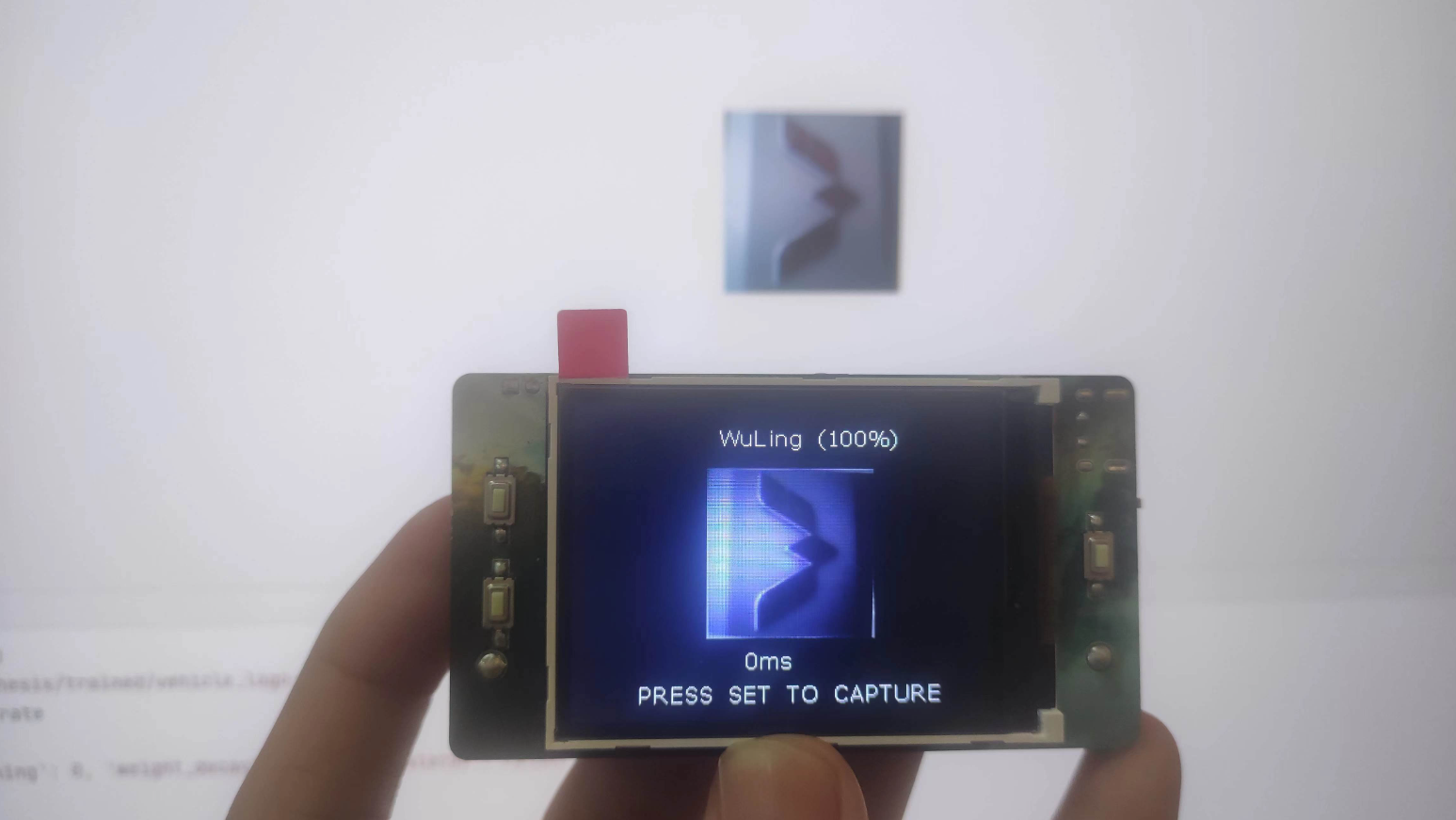
In this update, I will use the MAX78000FTHR development board and the expansion board in this project (hereinafter referred to as the MAX78000FTHR expansion board) to implement the classification and recognition of three types of car logos, and explain the implementation process. The following three images
demonstrate the recognition results of three car logos
: Wuling, Volkswagen, and Mazda. The three car brands are Wuling, Volkswagen, and
Mazda
. The training process for the model is as follows: Model Training -> Model

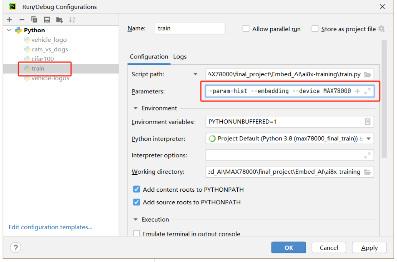
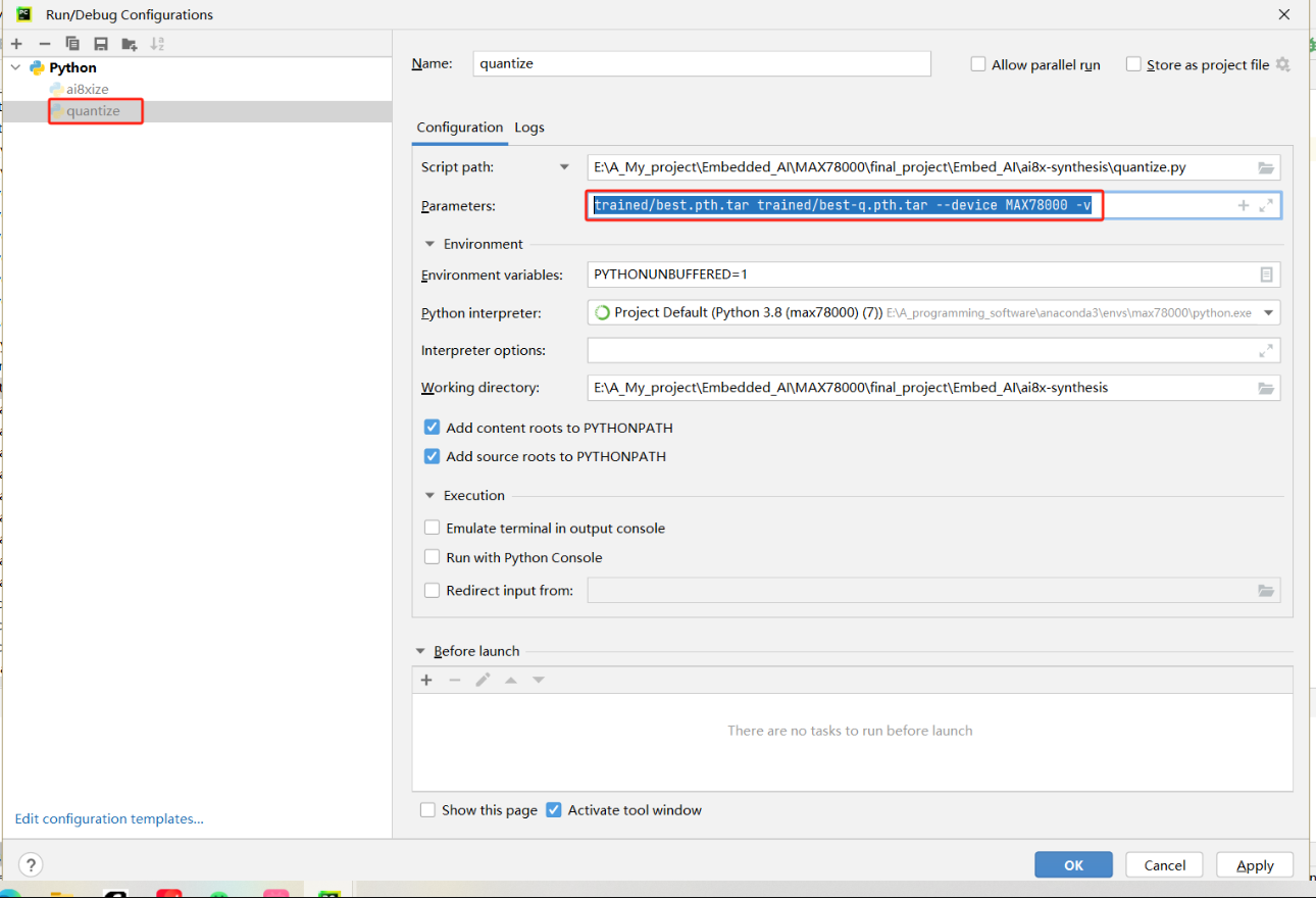
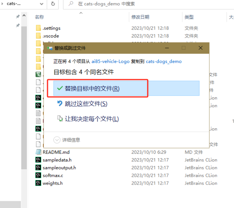
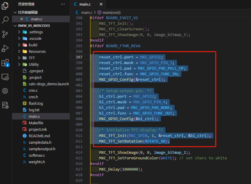
Quantization -> Model Evaluation -> Model Conversion. These four steps are explained below : 1. Three-Class Classification Training : Open the `train.py` file in the training project. This file requires input parameters. The following example uses cat and dog recognition. Find the `scripts/train_catsdogs.sh` file and copy the following parameters: --epochs 250 --optimizer Adam --lr 0.001 --wd 0 --deterministic --compress policies/schedule-catsdogs.yaml --model ai85cdnet --dataset vehicle_logo --confusion --param-hist --embedding --device Copy the MAX78000 file to the run parameters of train.py, as shown in the image below . Then click to run the train.py file. It will automatically load the parameters we just entered and start training. After training is complete, the quantization file needed for the next step will be generated in the logs folder, as shown in the image below . 2. Quantization Copy the best.pth.tar file generated in the previous step to the trained folder under the quantization project. Open the quantize.py file and configure the run parameters for it, as shown in the image below. The run parameters are: trained/best.pth.tar trained/best-q.pth.tar --device MAX78000 -v After configuration, run the quantize.py file. The best-q.pth.tar generated in the trained folder after running is the quantized model file. 3. Model Evaluation After obtaining the quantized model file, we switch back to the training project to evaluate the model. The file used for model evaluation is the same as the file used for model training, but the run parameters are different. Here we modify the run parameters of train.py to evaluate the model. The evaluation input parameters are as follows: --model ai85cdnet --dataset vehicle_logo --confusion Running the `train.py` file with the command `--evaluate --exp-load-weights-from ../ai8x-synthesis/trained/best-q.pth.tar -8 --device MAX78000` yields the following results: The effect is acceptable. 4. Model Conversion : Model conversion converts the trained model into a C file for easy deployment. Switching back to the quantization project, we need to use the `ai8xize.py` file. Similarly, we need to configure the running parameters for this file to complete the model conversion. The running parameters are as follows: `--verbose --test-dir demos --prefix ai85-vehicle_logo_3 --checkpoint-file trained/best-q.pth.tar --config-file networks/vehicle_logo-hwc.yaml --fifo --device MAX78000` --After running softmax, the development board project file we need will be generated in the demos folder under the quantization project, as shown in the figure below: This project file can be opened and edited using VS Code. Model Deployment In the previous step, I implemented the model training and finally obtained the chip project file. However, what was generated here is only a sample. The data input to the model is a sample generated by the training project. It cannot send the image captured by the camera to the model. Therefore, in this step, we will deploy the model to a usable project. 1. Model Migration First, open the project folder obtained from the model conversion, copy the cnn.c/h, softmax.c and weights.h files, and then paste them into the cats-dogs_demo example (this example can send the image captured by the camera to the model). When pasting, the window shown in the figure below will pop up. Select the "Replace files in destination" option. In this way, we will migrate the trained model to the original cat and dog classification project. 2. Program Modification First, modify the screen initialization function to adapt to the screen of the expansion board. Put the following code in the screen initialization position of the main function, as shown in the figure below: reset_ctrl.port = MXC_GPIO2; reset_ctrl.mask = MXC_GPIO_PIN_3; reset_ctrl.pad = MXC_GPIO_PAD_PULL_UP; reset_ctrl.func = MXC_GPIO_FUNC_IN; MXC_GPIO_Config(&reset_ctrl); /* Setup output pin. */ bl_ctrl.port = MXC_GPIO2; bl_ctrl.mask = MXC_GPIO_PIN_4; bl_ctrl.pad = MXC_GPIO_PAD_NONE; bl_ctrl.func = MXC_GPIO_FUNC_OUT; MXC_GPIO_Config(&bl_ctrl);


/* Initialize TFT display */
MXC_TFT_Init(MXC_SPI0, 1, &reset_ctrl, &bl_ctrl);
MXC_TFT_SetRotation(ROTATE_90);
Then modify the category definition in the program, that is, the content highlighted in the image below.

This definition is used to distinguish the categories. Change the array to the content shown in the image below. After modification,

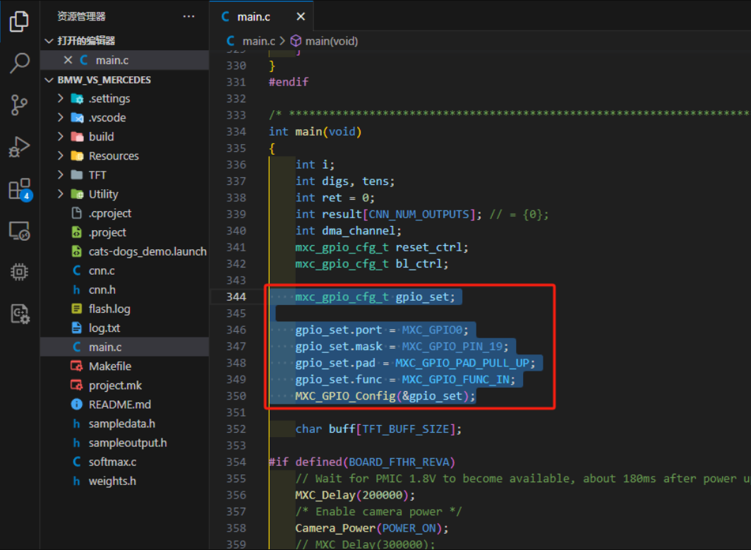
add the expansion board button code as shown in the image below:
mxc_gpio_cfg_t gpio_set;
gpio_set.port = MXC_GPIO0;
gpio_set.mask = MXC_GPIO_PIN_19;
gpio_set.pad = MXC_GPIO_PAD_PULL_UP;
gpio_set.func = MXC_GPIO_FUNC_IN; After initializing
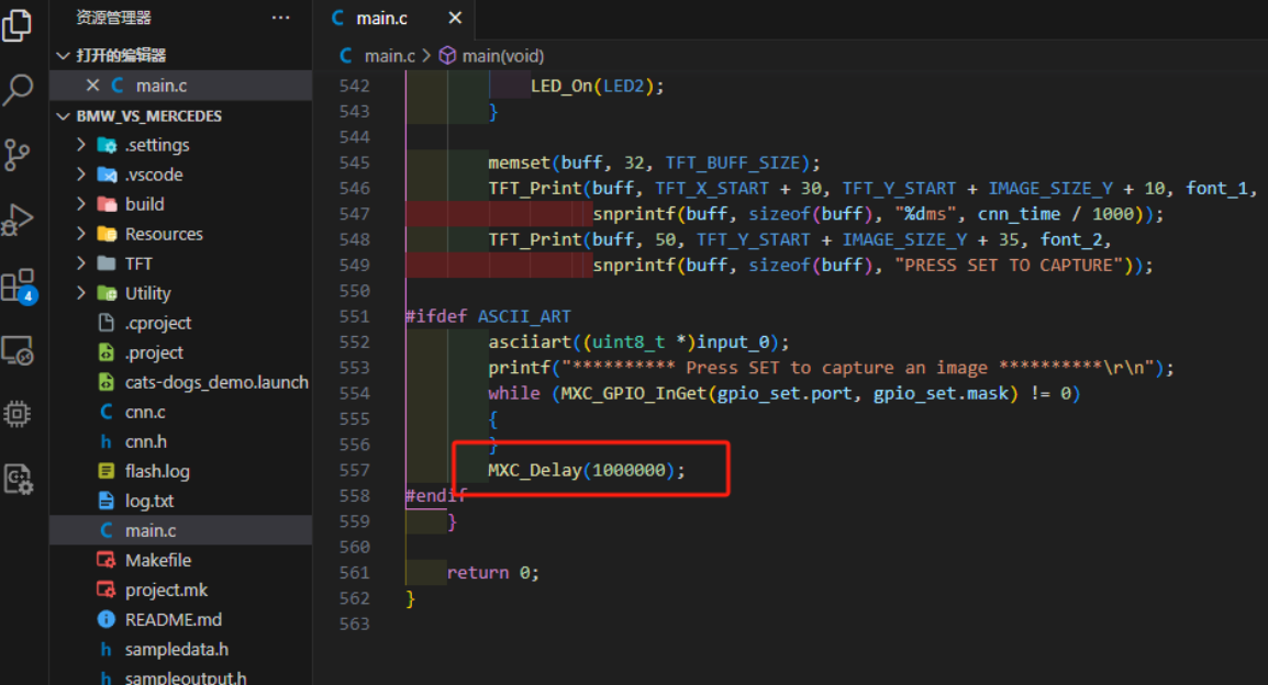
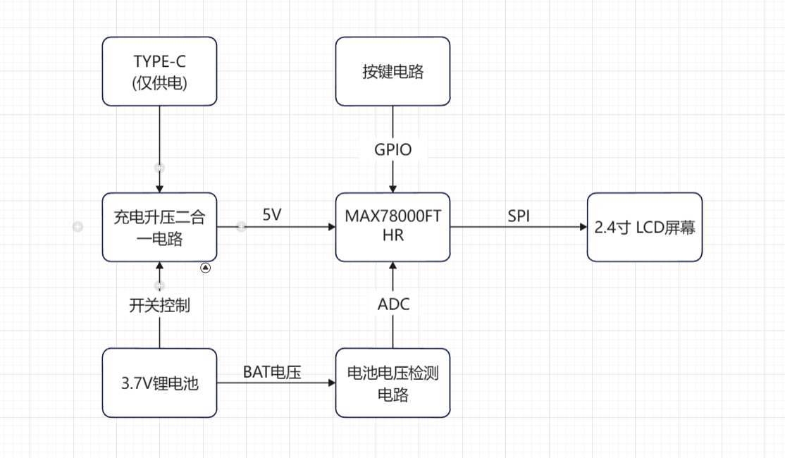
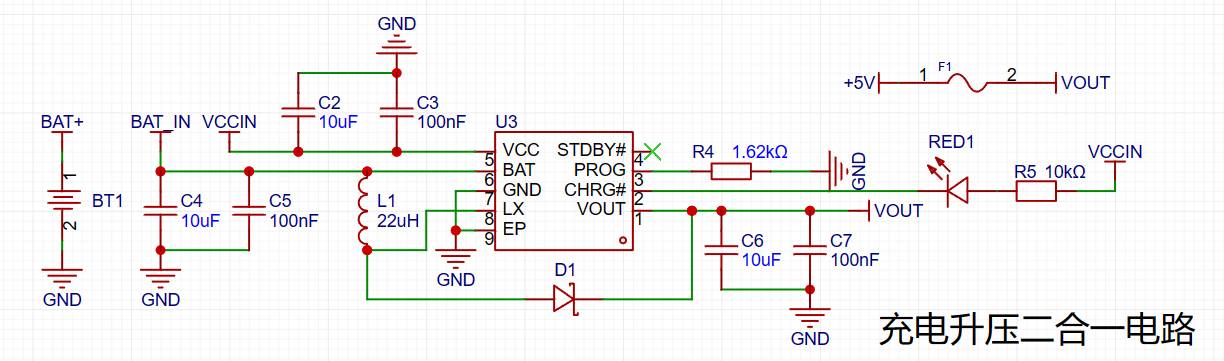
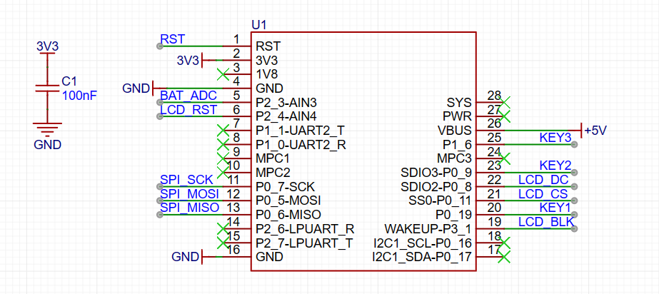
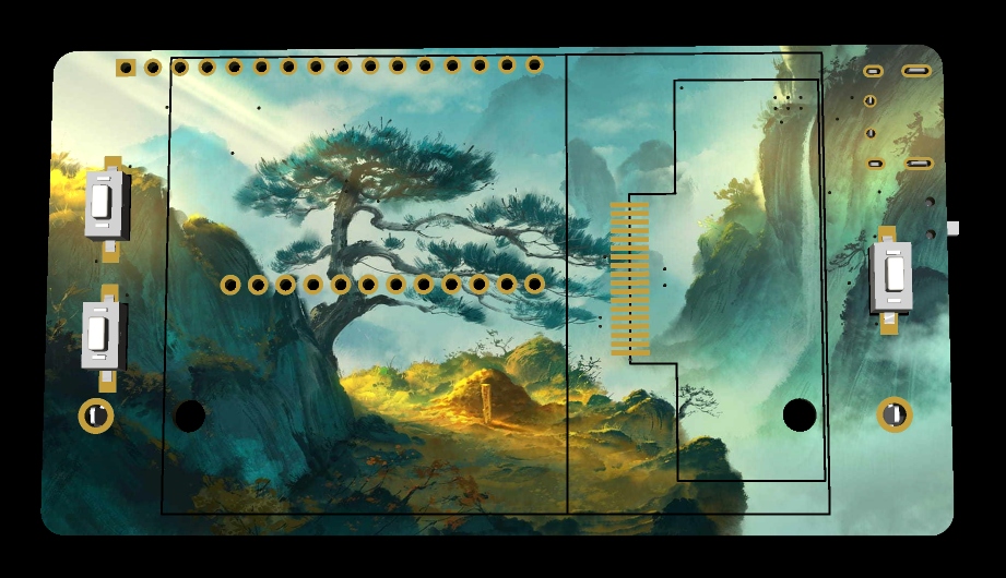
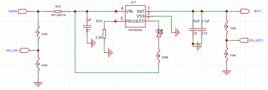
`MXC_GPIO_Config(&gpio_set); `, we can use the `MXC_GPIO_InGet()` function to obtain the high and low levels of the pins, thus determining whether a button is pressed. Since pressing a button pulls the pin level low, we replace all `!PB_Get(0)` code in the project with `MXC_GPIO_InGet(gpio_set.port, gpio_set.mask) != 0`. Then, we modify the camera image refresh function (note that this function is in the main function) as follows: ` while (MXC_GPIO_InGet(gpio_set.port, gpio_set.mask) != 0) { capture_process_camera();` The reason for this modification is that the original program cannot constantly view the content captured by the camera; it can only observe the captured image during shooting, which is not conducive to shooting. This modification allows for constant observation of the camera's image, thus enabling the capture of satisfactory footage. However , this requires adding a delay function after the next button press to prevent accidental touches, as shown in the image below. Due to the placement of the screen on my expansion board and the development board, the angle of the camera image is perpendicular to the viewing angle of the screen (90 degrees). Therefore, we need to modify the camera image display function. We replace `MXC_TFT_ShowImageCameraRGB565(TFT_X_START, TFT_Y_START + row, data565, w, 1);` in the `capture_process_camera` function with `MXC_TFT_ShowImageCameraRGB565(TFT_X_START + h - row, TFT_Y_START, data565, 1);`. h); This rotates the camera image. The principle behind this is that the camera data is displayed line by line. The original function rotates the image 90 degrees to the left. Therefore, the first row of data in the captured image should be the rightmost column of data in the normal image. So, instead of displaying the image data line by line, we display it column by column, starting from the rightmost column. This processed image appears normal to us. The location of this line of code is shown in the image below. The three-class recognition code is attached: WuLing-VW-Mazda.7z. This concludes the program modifications. For a demonstration of the effects, see the demonstration of the three car logo classification recognition effects. The quantization process is too large and has been uploaded to a cloud drive. A link to the cloud drive will be provided in the comments section later. This concludes the update of the MAX78000FTHR edge AI application. ————————————— Manual Divider ————————————— Before November 17th, the project analysis focuses on the MAX78000FTHR expansion board, which enables the capture and storage of images to an SD card. This project facilitates image acquisition using the MAX78000FTHR, obtaining actual footage from the onboard camera, thus significantly improving dataset acquisition efficiency. Using these images for MAX78000 model training can improve the accuracy of camera recognition. The following diagrams show the hardware and software structures. The schematic diagram is shown below. Design Description: This project uses TP5400 for power management. When powered by an external power source, it can charge a 3.7V lithium battery and output 5V. When the external power source is not available, it can boost the 3.7V voltage to 5V, thus achieving a two-in-one charging and boosting function . The screen display uses a 2.4-inch screen with ILI9341 driver, which can directly use the screen driver provided by the MAX78000 official website. The hardware connection is shown below. For the button operation section, because the buttons on the MAX78000FTHR are too small and inconvenient to operate, buttons were reconnected on this expansion board to achieve button operation. The schematic diagram is shown below. The connection between the MAX78000FTHR and other parts is shown below. PCB Design Description: In the PCD design section, this project uses color... The silkscreen printing is very attractive. The 3D preview image is shown below, and the actual product image is shown below . Note: If you do not want to use color silkscreen printing on the PCB board, simply delete the color silkscreen image from the PCB. This will not affect the circuit operation. Alternatively, you can directly use the ordinary silkscreen Gerber file in the attachment for PCB fabrication. Actual product demonstration: Front view, Back view. November 10th bug update: There is a bug in the camera shooting program. After pressing the record button, the screen displays the camera image captured when the button is pressed, but when the save button is pressed, it saves the image captured when the save button is pressed. This is problematic . Solution: Save the image captured when the record button is pressed, save it to the SD card when the save button is pressed, and delete it when the discard button is pressed. The key code is shown below: #ifdef SD // Capture images on the basis of SD card opening


cnn_img_data_t img_data = stream_img(g_app_settings.imgres_w, g_app_settings.imgres_h,
g_app_settings.pixel_format,
g_app_settings.dma_channel);
memset(buff, 32, TFT_BUFF_SIZE);
TFT_Print(buff, 37, TFT_Y_START + IMAGE_SIZE_Y + 5, font_2,
snprintf(buff, sizeof(buff), "PRESS UP to Save Image"));
TFT_Print(buff, 0, TFT_Y_START + IMAGE_SIZE_Y + 35, font_2,
snprintf(buff, sizeof(buff), "PRESS DOWN to Discard Image"));
// MXC_Delay(1000000);
while (1)
{
// SD card is enabled. save image
if ( Key_get() == key_up)
{
save_stream_sd(img_data, NULL) ; area_t area ;
area . TFT_Print(buff, 0, TFT_Y_START + IMAGE_SIZE_Y + 20, font_2, snprintf(buff, sizeof(buff), "Saved Image to %s Successed", path)); break; } // discard image if (Key_get() == key_down) { area_t area; area.x = 0; area.y = 180; area.w = 320; area.h = 60; MXC_TFT_ClearArea(&area, BLACK); memset(buff, 32, TFT_BUFF_SIZE); TFT_Print(buff, 30, TFT_Y_START + IMAGE_SIZE_Y + 20, font_2, snprintf(buff, sizeof(buff), "Discard Image Successfully")); break; } } MXC_Delay(200000); #endif The attached project has been updated.
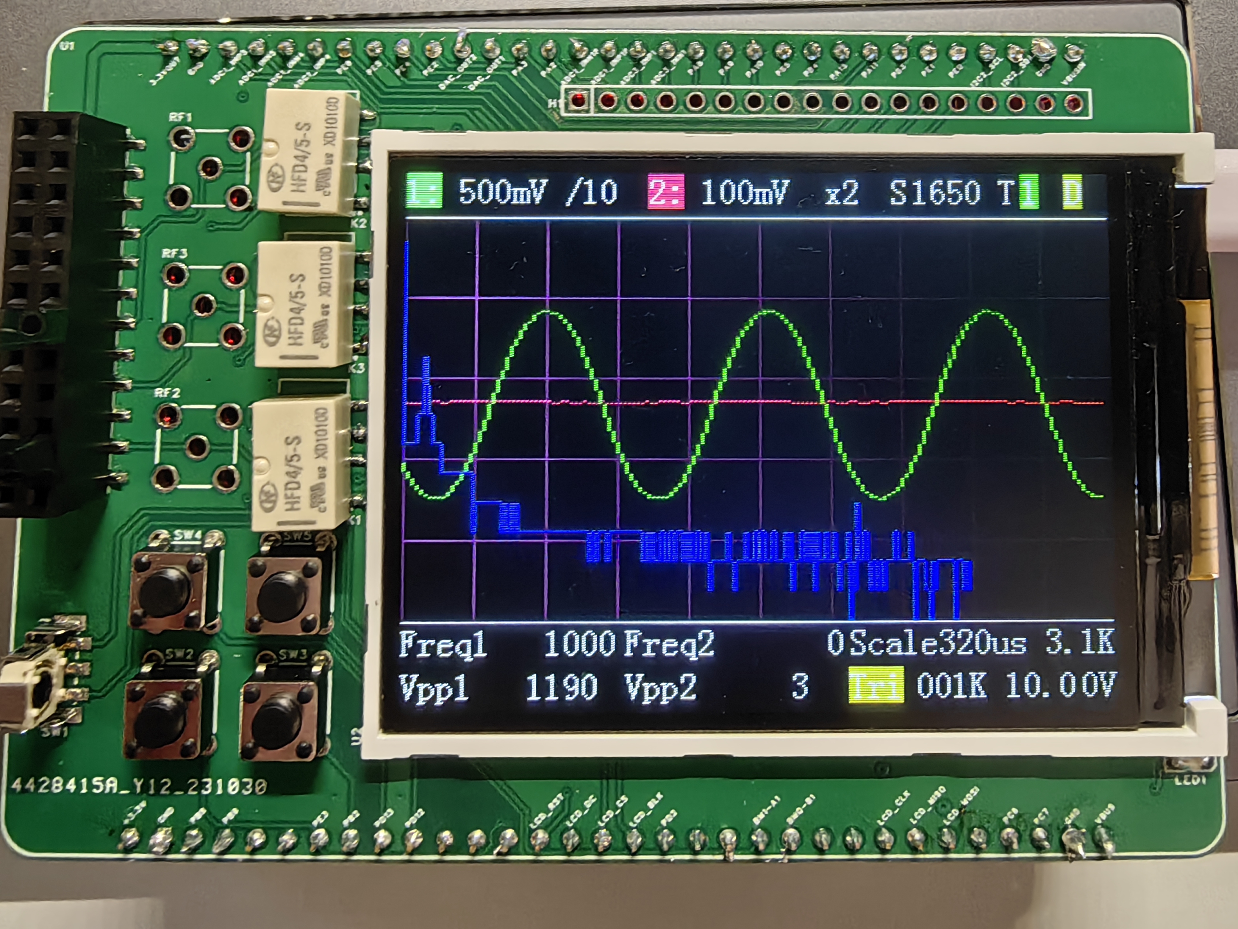
Instrumentation Training Camp Project: Oscilloscopes used with the H750 core board
Project Principle: This project utilizes analog circuit components such as resistor dividers, operational amplifiers, and comparators to implement signal conditioning, amplification, shifting, filtering, and comparison functions to adapt to the input and output ranges of the STM32H750's ADC and DAC, thus realizing the oscilloscope's sampling and output functions. It also uses switches and voltage divider networks to implement the segmentation function of analog input and output channels, improving the measurement accuracy and output resolution of small signals. Furthermore, it utilizes the STM32H750's timer function to implement triggering and frequency measurement functions.
Project Functionality: This project can function as a dual-channel oscilloscope, measuring analog signals within a ±15V range and converting them into digital signals within a 0-3.3V range for sampling by the STM32H750's ADC. It can also function as a single-channel signal source, outputting analog signals within a ±10V range, which are then generated by the STM32H750's DAC. It can also square-wave the input signal and utilize comparators and timers to implement triggering and frequency measurement functions.
BOM_Board1_PCB1_2023-10-30.xlsx
AFE03 (1).rar
PDF_H750 Oscilloscope.zip
Altium_H750 Oscilloscope.zip
PADS_H750 Oscilloscope.zip
BOM_H750 Oscilloscope.xlsx
97178
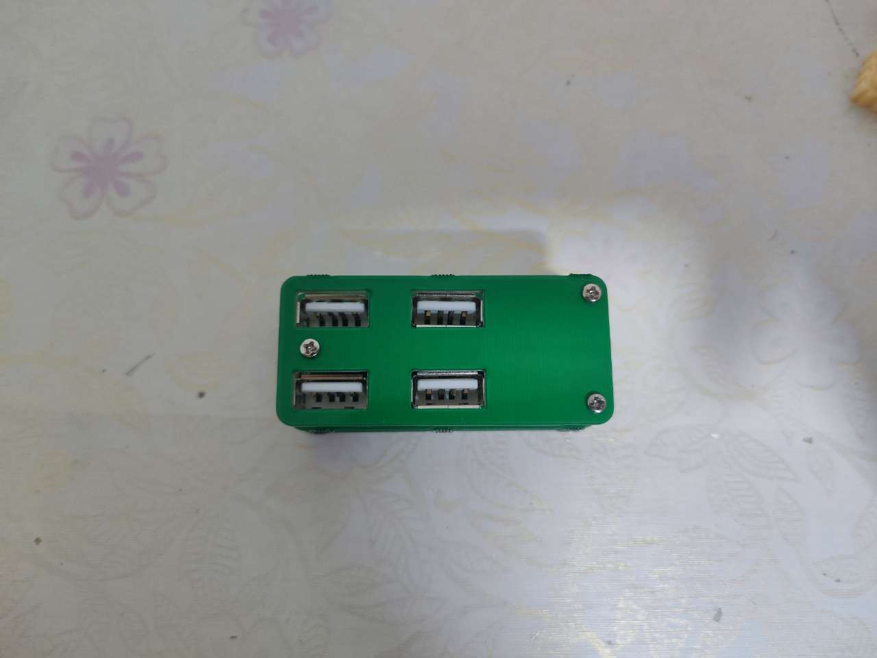
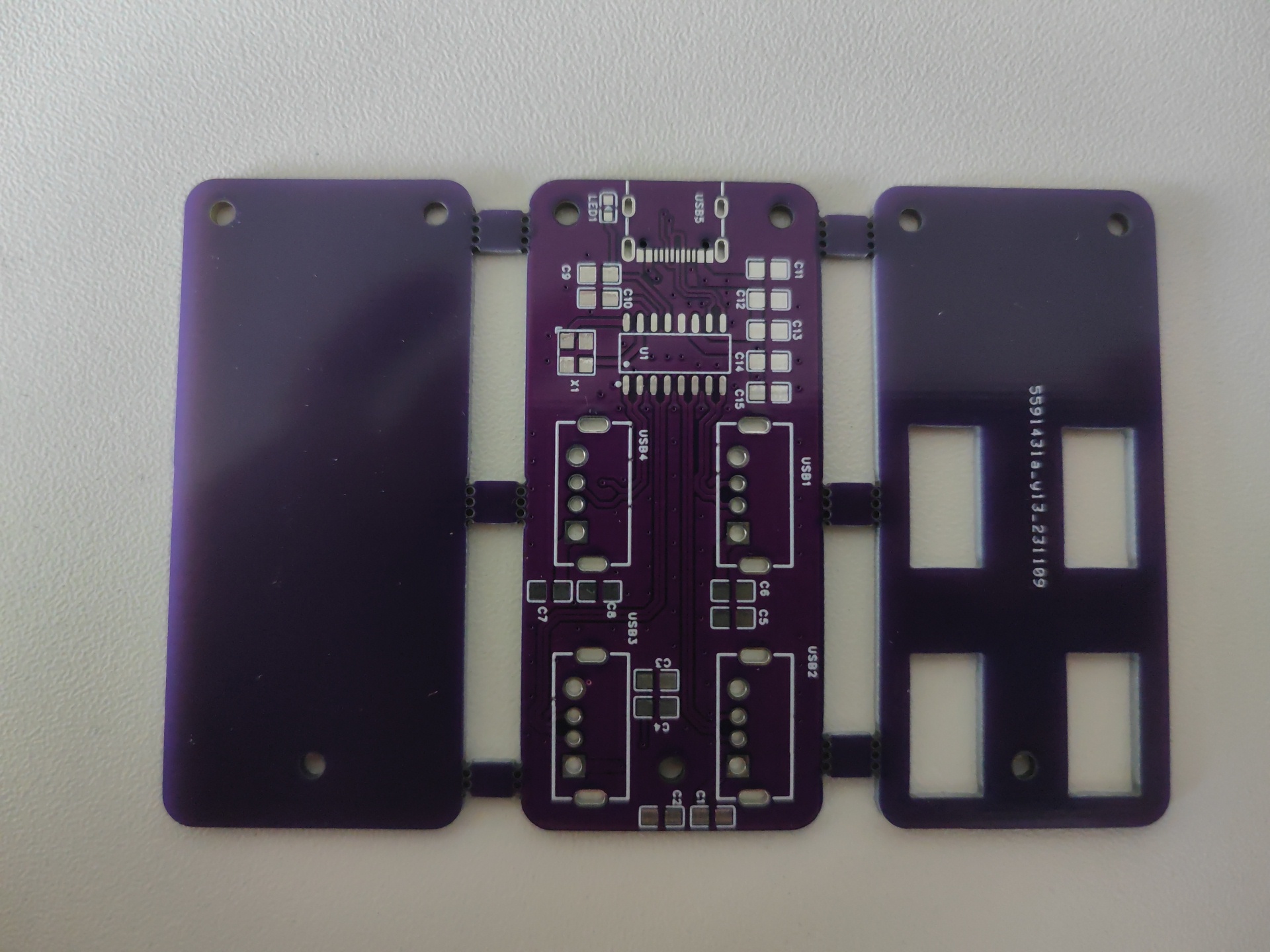
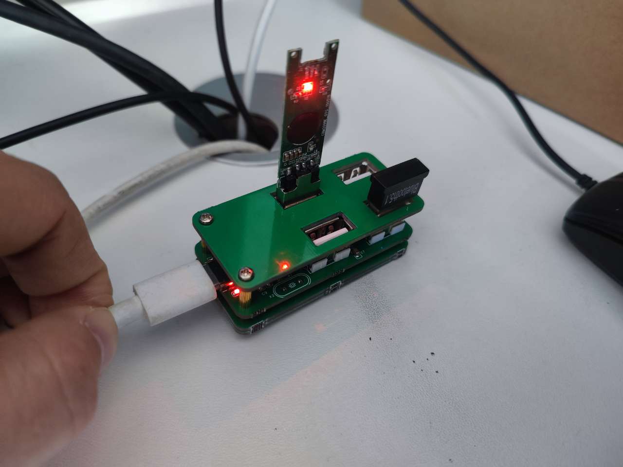
Based on SL2.1A USB 1-to-4 hub (verified)
Integrated 4 USB ports; Chip: SL2.1S. Hub chip solution verification board. (Verified) (Replica!!!!)
Anyone who's into electronics
knows that computers often don't have enough USB ports, especially ultrabooks, which usually only have 2-3. After plugging in a keyboard, mouse, and other devices, there are often no usable ports left. Frequent plugging and unplugging can cause USB ports to loosen, and sometimes the cables are too short, which is incredibly annoying. USB ports are also prone to damage (don't ask me how I know, I've already ruined a 3.0 USB port). I previously bought a USB 2.0 hub, but it became unstable when plugging in just two USB devices. To solve this problem, I made a 1-to-4 USB 2.0 hub based on the SL2.1A chip. (I'm still modifying the board in my dorm on May 20th, what a miserable time!) I've
replicated this project from this link: https://oshwhub.com/li31951/usb-ji-xian-qi (detailed data and information can be found in this link).
I've added working LEDs and cutouts for separate processing!

PDF_SL2.1A USB 1-to-4 Hub (Verified).zip
Altium_SL2.1A USB 1-to-4 Hub (Verified).zip
PADS_SL2.1A USB 1-to-4 Hub (Verified).zip
BOM_Based on SL2.1A USB 1-to-4 Hub (Verified).xlsx
97179
AiPi-LRW-TH1
Anxinco Mini-Pat LoRaWAN Sensor Universal Board
I. Overview
The AiPi-LRW-TH1 is a LoRaWAN sensor general-purpose board designed by the AiPi open-source team for the Ra-08H. It includes a general-purpose sensor interface supporting I2C+ADC+GPIO, a battery power interface, and a battery charging interface, and supports DIP switches to turn the power on and off.
The AiPi-LRW-TH1 can be applied in various scenarios to create smart agriculture, smart streetlights, and smart homes. After sensor data is collected by the Ra-08H, it is transmitted to the RG-02 gateway via the LoRaWAN protocol, and then uplinked to the LoRaWAN server. The data transmission distance is up to 4 kilometers. Low-power standby is achieved in standby mode when no data is being transmitted.

II. System Block Diagram

III. Sensor Interface
A GPIO interface supporting I2C+ADC is provided to accommodate sensors with various communication methods.

IV. Charging Circuit
The battery is charged using a Type-C interface and equipped with a charging indicator light.
V. Battery DIP Switch
The DIP switch can switch between battery power and power supply.

PDF_AiPi-LRW-TH1.zip
Altium_AiPi-LRW-TH1.zip
PADS_AiPi-LRW-TH1.zip
BOM_AiPi-LRW-TH1.xlsx
97180
Small size ST-LINK/V2-1
[For personal use] This ST-Link downloader was made using an STM32F103CBT6. It can support other download types, such as J-Link and DAP-Link, by changing the firmware.
I. Fabrication and Soldering
1. Schematic Diagram
: The ST-Link circuit on the Pandora IOT development board for the STM32L475VET6 from Zhengdian Atomic
was largely copied, but the reset pin for the main control chip was not brought out.
2. PCB Design:
The entire PCB was designed using LCSC EDA.
Firmware download was performed using the software 【STM32 ST-LINK Utility】 and 【STM32 CubeProgrammer】 ,
with an SWD download interface and one serial port brought out
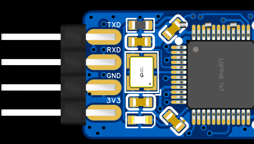

. 3. Soldering:
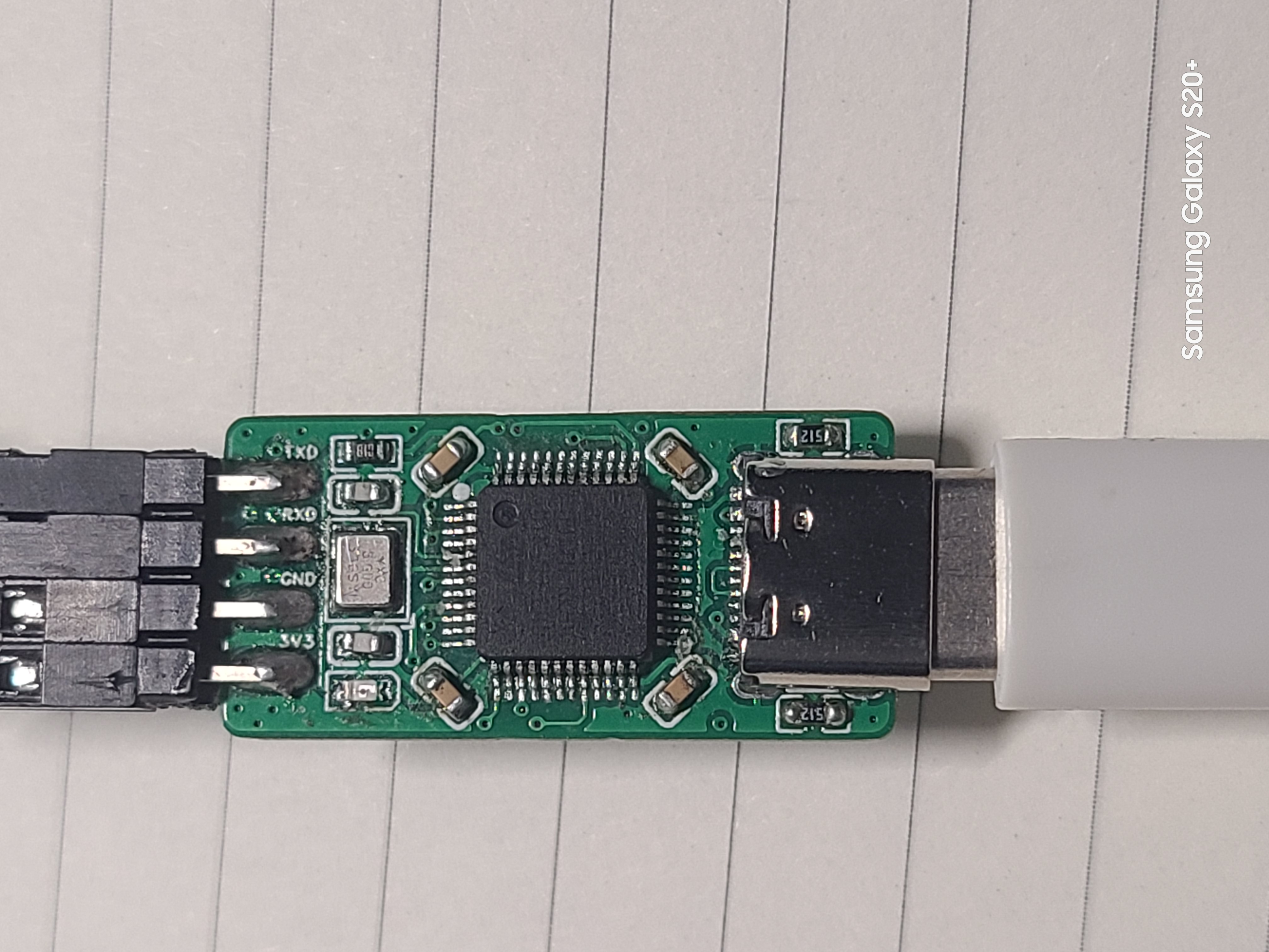
The onboard chip used is the 【STM32F103CBT6】. The chip integrates 128KB of Flash memory and 20KB of Static Random Access Memory (SRAM).
All resistors and capacitors are 0603 packages, which can be soldered using a hot plate, heating pad, or hot air gun.
The onboard chip's download interface is displayed as a "test point" for easy firmware burning.
It uses a USB-C interface for convenient connection.
4. Finished Product Display

II. Firmware Burning and Testing
1. Original Firmware Burning
A ready-made ST-Link programmer is required. Then, use a soldering iron and DuPont wires to bring out the onboard chip's download port and use ST-Link to download the original firmware.
[Note] Since PA9 and PA10 are not brought out on the board, when purchasing a new chip, it can only be unlocked using software.
You can use an ST-Link programmer and the [STM32 ST-LINK Utility] software to unlock the chip (search online for specific steps).
Firmware can be downloaded using [STM32 ST-LINK Utility] or [STM32 CubeProgrammer] software (search online for specific download steps).
2. Firmware Upgrade After Download
Using TM32 Upgrade using the firmware upgrade tool included with CubeProgrammer. You can connect via USB-C cable to upgrade.
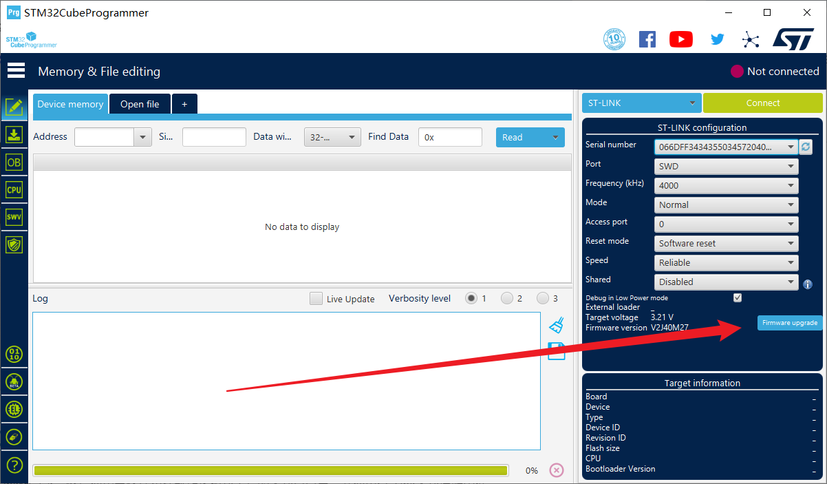

Click "Open in update mode," wait for the detection, then click "Upgrade" and wait for the download to complete.
3. To change the firmware
, you can use the ST-Link to J-Link converter to convert the firmware.

Follow the command prompts to complete the operation.
Only ST-Link and J-Link firmware were tested; DAP-Link firmware download was not tested.
4. Testing showed that the board
supports drag-and-drop hex programming from a USB flash
drive. After testing, the board can be programmed and used normally on STM32F1 series chips, but not on STM32F4 series chips. The reason is under investigation and has not been determined.


The board can be recognized normally in both Keil and STM32 Cube Programmer software.


The virtual serial port can be recognized normally in the serial port debugging assistant, and it can be recognized normally under both different firmware versions. The image shows a loopback test.
III. The
issue of not being able to download to F4 will be further investigated.
ST-LINK Utility.rar
STLinkReflash (conversion tool).zip
STLinkV2.J28.M18.bin
PDF_Small Size ST-LINK-V2-1.zip
Altium_small-size ST-LINK_V2-1.zip
PADS_Small Size ST-LINK_V2-1.zip
BOM_Small-volume ST-LINK_V2-1.xlsx
97181
SW3556-1
The SW3556 features dual USB-C ports, supporting 7A (140W) fast charging output via both USB-C ports, and supports PPS/PD/QC/AFC/FCP/SCP/PE/SFCP/TFCP fast charging protocols.


Schematic

PCB

PDF_SW3556-1.zip
Altium_SW3556-1.zip
PADS_SW3556-1.zip
97182
electronic


 京公网安备 11010802033920号

 DSA6301JI1BB-T


