Related Resources:
CW32 Digital Voltmeter and Ammeter Training Camp Project Tutorial Document | LCSC Development Board Technical Documentation Center
Explanation Video:
Step-by-Step Guide to Building a Voltmeter and Ammeter_bilibili
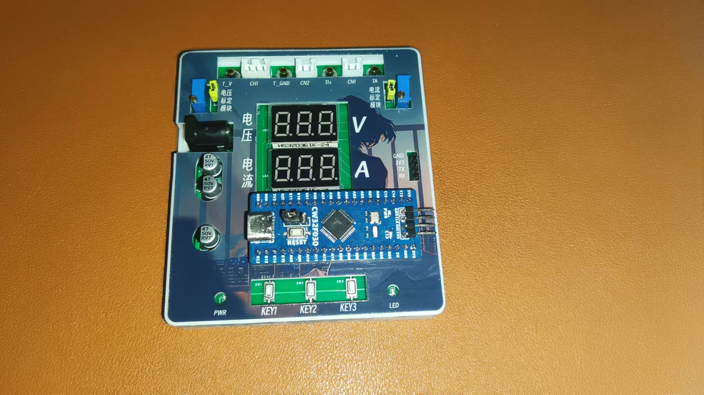
Physical Diagram

Hardware Design
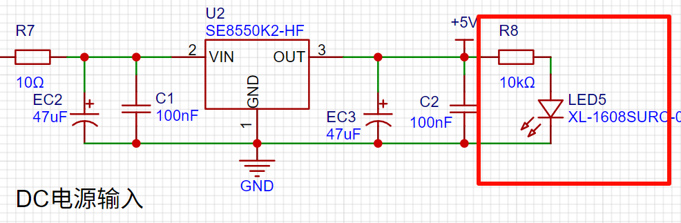
1. Power Supply Circuit

LDO (Low Dropout Linear Regulator) Selection
This project uses an LDO as the power supply. Considering that most actual voltmeter products are used in industrial scenarios with 24V or 36V power supplies, this project selected the SE8550K2 with a maximum input voltage of up to 40V as the power supply. The main reason for not using a DC-DC step-down circuit to deal with the large voltage drop is to avoid introducing DC-DC ripple interference during the design process, and the secondary reason is to reduce project costs.
2. MCU Selection Analysis:
Key Advantages of CW32 in this Project
: Wide operating temperature range: -40~105℃;
Wide operating voltage: 1.65V~5.5V (STM32 only supports 3.3V systems)
; Strong anti-interference: HBM ESD 8KV; All ESD reliability reaches the highest international standard level (STM32 ESD 2KV);
Project Focus - Better ADC: 12-bit high-speed ADC, achieving ±1.0LSB INL 11.3ENOB; Multiple Vref reference voltages... (STM32 only supports VDD=Vref)
; Stable and reliable eFLASH technology.
A detailed explanation of these advantages will be provided in the chapters on ADC sampling and related extensions.
The main characteristics of the CW32 ADC:
This project focuses on the 4 reference voltage sources.
(Content from the "CW32x030 User Manual")

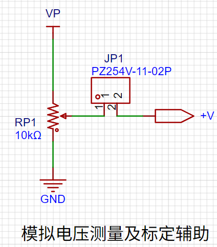
3. Voltage Sampling Circuit and Calibration Circuit:
The voltage divider resistors in this project are designed to be 220K+10K, therefore the voltage division ratio is 22:1 (ADC_IN11).

The calibration circuit is used to assist in the calibration of the voltage sampling circuit.
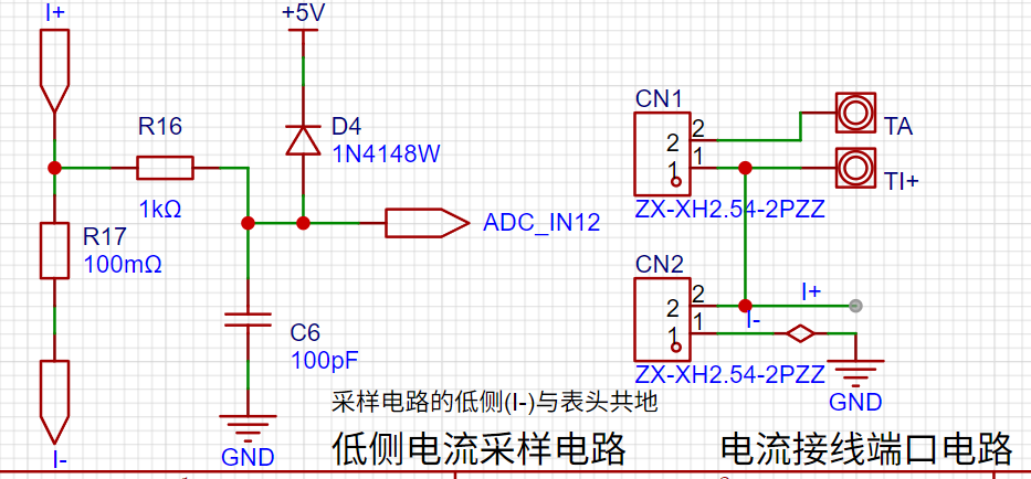
4. Current Sampling Circuit:
This project uses a low-side current sampling circuit for current detection. The low-side of the sampling circuit shares a common ground with the development board's meter interface
. Do not solder R17 during learning!
The calibration circuit is used to assist in the calibration of the current sampling circuit.
Do not solder resistor R17 during calibration!

5. Digital Tube Display:
This project uses a digital tube as the display device, specifically a 0.36-inch common cathode digital tube.

6. LED Indicators:
Power indicator,
user LED.

7. Button Circuit Design:
GPIO needs to be configured as pull-up input mode .

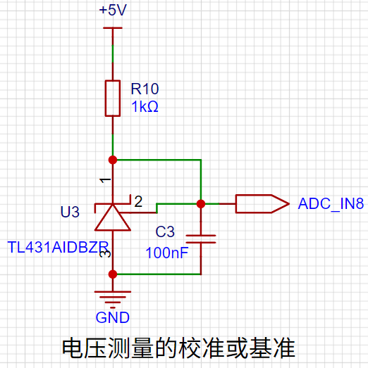
8. TL431 Circuit Design for Voltage Measurement and Calibration:
This project adds an extra TL431 circuit to provide a 2.5V reference voltage, which can be used to provide an external voltage reference for the chip to calibrate the AD converter.
Software Design
: 1. Using Systick as the main interrupt:
Based on Systick, an interrupt occurs every 1ms. All places requiring timed interrupts are placed in the Systick interrupt service function .
//cw32f030_systick.c
/**
* @brief This function handles System tick timer.
*/
void SysTick_Handler(void)
{
/* USER CODE BEGIN SysTick_IRQn */
uwTick += uwTickFreq;
Systick_Use();
/* USER CODE END SysTick_IRQn */
}
//main.c
/**
* @brief Called once every 1ms interrupt
*
*/
void Systick_Use()
{
if (++Adc_tc >= 1)
{
Adc_tc = 0;
Adc_ref = 1;
}
if (++Nixie_ref >= 2)
{
Nixie_ref = 0;
Nixie_Display();
}
if (++Key_tc >= 10)
{
Key_tc = 0;
Key_Loop();
}
if (++Nixie_cha_tc >= 300)
{
Nixie_cha_tc = 0;
Nixie_cha_ref = 1;
}
}
2. Button Function
K1: Switching Mode
Mode 0: Displays normal voltage and current values (the upper row of digital tubes displays the voltage value .V or .V automatically switches, the lower row displays the current value _ . ** A)
Mode 1: Voltage 5V calibration value setting. The upper row of digital tubes displays 5.05. The next row displays the current voltage value in .V or .V. In this mode, the multimeter should be set to 5.00V when measuring the measured position. Pressing the K2 key will calibrate the current value to 5V.
Mode 2: 15V voltage calibration setting. The upper row of the digital display shows 5.15. The next row displays the current voltage value in .V or .V. In this mode, the multimeter should be set to 15.0V when measuring the measured position. Pressing the K2 key will calibrate the current value to 15V.
Mode 3: 0.5A current calibration setting. The upper row of the digital display shows A.0.5. The next row displays the current current value in _.**A. Pressing the K2 key will calibrate the current value to 0.5A.
Mode 4: Current calibration value setting of 1.5A. The upper row of the digital tube displays A.1.5. The lower row displays the current current value *.** A. After pressing the K2 key, the current value is calibrated to 1.5A.
K2: Select to confirm the calibration value in non-mode 0 cases. K3
: Directly switch to mode 0.
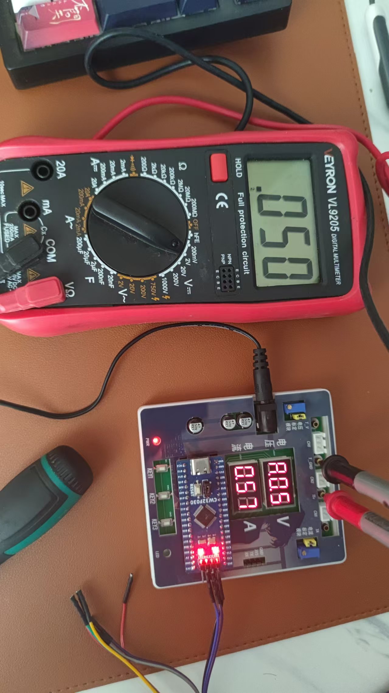
3. Calibrate
5V

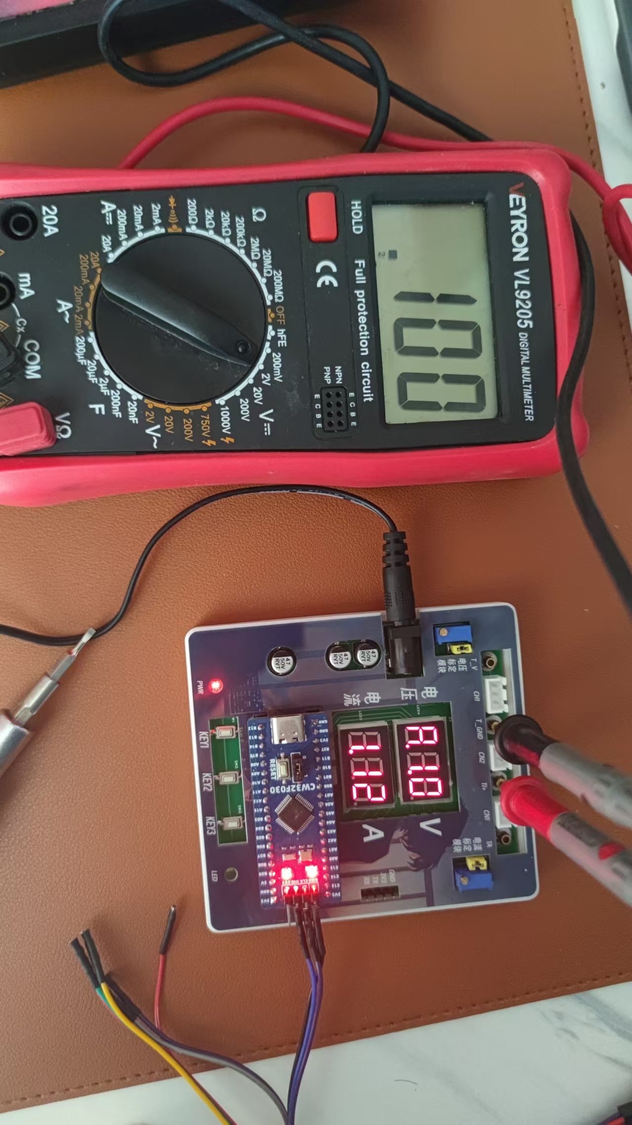
10V.
Because a 12V charger is used as the power source, it is not possible to calibrate 15V

0.5A
1A.
WeChat_20240823150404.mp4
CW32F030C8T6.zip
PDF_CW32-based voltage and current meter.zip
Altium_CW32-based voltage and current meter.zip
PADS_CW32-based Voltage and Current Meter.zip
BOM_CW32-based voltage and current meter.xlsx
92864
ammeter and voltmeter
LCSC GeoStar CW32 Digital Voltage and Current Meter
II. Hardware Design Details
Power Supply Circuit Design:
This project uses an LDO (Low Dropout Linear Regulator) as the power supply. Considering the actual application scenario, the SE8550K2 with a maximum input voltage of 40V was selected. A DC-DC step-down circuit was not used primarily to avoid potential ripple interference and to reduce costs.
MCU Selection Analysis:
This project uses the LCSC CW32F030C8Tx development board as the main controller. The selection considered computing power, I/O ports, and peripheral requirements. The CW32's advantages lie in its wide operating temperature range, wide operating voltage, strong anti-interference capability, and excellent ADC performance.
Voltage Sampling Circuit Design :
The voltage divider resistors are designed as 220K+10K, with a voltage division ratio of 22:1. Considering safety factors, the maximum measured voltage is designed to be 30V, but it can actually display 99.9V or 100V. The ADC reference voltage is 1.5V, which can be configured through the program. To reduce power consumption, the low-side resistor is selected as 10K. Calculations show that the high-side resistor is 220K. For measuring lower voltages, the voltage divider resistor can be replaced and the program modified to improve accuracy. For measuring higher voltages, the voltage reference can be increased to expand the range.
The current sampling circuit design
uses a low-side current sampling circuit with a designed sampling current of 3A and a sampling resistor of 100mΩ. Considering the voltage difference, power consumption, and amplification factor caused by the current sensing resistor, a 1W packaged metal wire-wound resistor was selected. To cope with different operating environments, especially high-current scenarios, the R0 resistor can be replaced with constantan wire or a shunt.
The digital tube display design
uses two 0.28-inch three-digit common-cathode digital tubes as display devices. Compared to a display screen, digital tubes have better recognition in complex environments and better mechanical performance. The current-limiting resistor is configured with 300Ω to achieve good display effect. The digital tube uses a dynamic scanning display driving method.
The LED indicator design
includes an additional power indicator and an IO working indicator. The power indicator LD_PWR is active low (on), and to reduce the current consumption of the LED, a 10K current-limiting resistor was selected.
The button
control circuit is designed to be simple, thanks to the CW32's internal I/O ports which can be configured with pull-up and pull-down resistors, eliminating the need for external configuration. One end of the button is connected to the MCU's I/O, and the other end is grounded. When the button is pressed, the I/O is pulled low. An additional
TL431
circuit is added to provide a 2.5V reference voltage, which can be used to provide an external voltage reference for calibrating the AD converter. The TL431 is a precision programmable reference device with high accuracy, adjustable output voltage, and a certain amount of current sinking capability. In this project, it is mainly used to learn the relevant application principles.
WeChat image_20240822151706.jpg
PDF_Ammeter and Voltmeter.zip
Altium_current_voltmeter.zip
PADS_Ammeter and Voltage Meter.zip
BOM_CurrentVoltage Meter.xlsx
92866
electronic


 京公网安备 11010802033920号

 ASM5P23S08AgG1-16-ST


