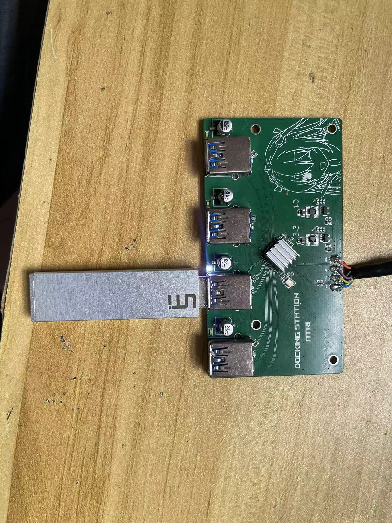
This project , a 1-to-4 USB 3.1 Gen2 expansion dock based on VL822
, is modified from the open-source project by arti (oshwhub.com). The main difference is in the power supply section. Because it was made using readily available materials, some differential wiring was optimized, and the speed directly reaches the full potential of USB 3.1. The test USB flash drive was one I made myself 5 years ago.
PDF_USB3.1 gen2 1-to-4 Split Expansion Based on VL822.zip
Altium_USB3.1 gen2 1-to-4 Split-Output Based on VL822.zip
PADS_USB3.1 gen2 1-to-4 Split-Output Based on VL822.zip
BOM_USB3.1 gen2 1-to-4 expansion based on VL822.xlsx
92392
#Training Camp# Oscilloscope 5779426A
This project involves building a simple digital oscilloscope through schematic design, PCB design, soldering, and experimentation.
The GD32E230C8T6 minimum system board was used, and a TFT screen was used to display the waveform.
Oscilloscope video.mp4
PDF_#Training Camp#Oscilloscope 5779426A.zip
Altium_#Training Camp#Oscilloscope 5779426A.zip
PADS_#Training Camp#Oscilloscope 5779426A.zip
BOM_#Training Camp#Oscilloscope 5779426A.xlsx
92393
Three types of reminder circuits based on LM358
Three types of reminder circuits based on LM358
Three Alarm Circuits Based on LM358
In modern electronic design, the operational amplifier LM358 is widely used in various signal processing circuits due to its low power consumption, high gain, and low noise characteristics. This article introduces three alarm circuit designs based on LM358, used for voltage monitoring, status indication, and multi-functional alarms, respectively.
1. Voltage Monitoring Alarm Circuit
The first project designs a voltage monitoring alarm circuit. This circuit uses a comparator composed of multiple operational amplifiers LM358 to detect whether the input voltage exceeds a set threshold. When the input voltage exceeds the range, the comparator output signal triggers logic gates and a timer, thereby lighting up an LED and activating a buzzer to issue an alarm signal.
In this circuit, the LM358 is configured as a voltage comparator, comparing the input voltage with a reference voltage. If the input voltage is higher than the reference voltage, the op-amp outputs a high level, and the logic gate further processes the signal to control the operation of the LED and buzzer. This design is often used in power supply voltage monitoring systems to remind users of the voltage status through visual and audible feedback.
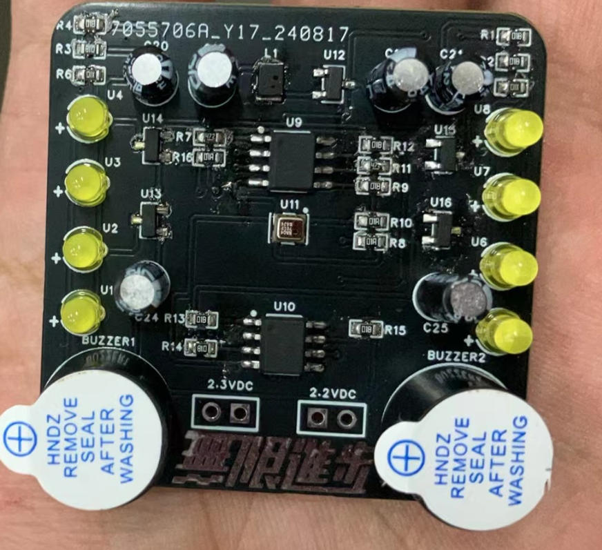
2. Status Indication Alarm Circuit
The second project designs a status indication alarm circuit. Its main function is to display the system status through an LED array and issue an alarm via a buzzer when necessary. This circuit also uses the LM358 operational amplifier as its core component for voltage comparison.
Multiple LM358 comparators detect different voltage inputs, triggering LEDs to display different states when an abnormality is detected. Simultaneously, a Schmitt trigger stabilizes the signal to prevent false alarms caused by voltage fluctuations. When certain conditions are met, a buzzer is activated to alert the user.
This circuit has wide applications; for example, in battery management systems, LED indicators display the battery's charging and discharging status, while a buzzer sounds an alarm when the battery level is too low or too high.
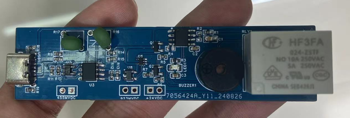
3. Multifunctional Alarm Reminder Circuit
The third project is a multifunctional alarm reminder circuit that integrates LED indication, audible alarm, and motor drive functions. This circuit is based on the LM358 and controls different alert methods by comparing input voltages.
In this design, the LM358 operational amplifier compares the input voltage with a reference voltage. When an abnormal voltage is detected, logic gates and timers generate corresponding control signals to drive the LED array and buzzer to sound an alarm. In addition, the circuit also controls a small motor to provide additional physical feedback, such as vibration alerts. This versatile design allows the circuit to be applied in situations requiring multiple alert methods, such as security systems or industrial equipment monitoring.

In summary
, LM358-based alert circuits are widely used in electronic engineering due to their flexible design and rich functionality. This article introduces three circuits designed for voltage monitoring, status indication, and multi-functional alarms, respectively, demonstrating the diverse applications of the LM358 in alert circuits. These circuits not only provide reliable visual and audible alerts but also enable physical feedback through motor drive, offering users a more comprehensive alert solution.
PDF_Three Alarm Circuits Based on LM358.zip
Altium_Three Alert Circuits Based on LM358.zip
PADS_Three Alert Circuits Based on LM358.zip
BOM_Three Alert Circuits Based on LM358.xlsx
92394
Ice Bluetooth Lyrics ESP32 Version
Play music via Bluetooth or the internet and display lyrics synchronously on a full-color dot matrix screen.
7d5fe360b7801b270276a516947b4f01.mp4
PDF_Ice Bluetooth Lyrics ESP32 Version.zip
Altium_Ice Bluetooth Lyrics ESP32 Version.zip
PADS_Ice Bluetooth Lyrics ESP32 Version.zip
BOM_Ice Bluetooth Lyrics ESP32 Version.xlsx
92395
I also built a simple oscilloscope with the help of my teacher.
This is a simple oscilloscope based on an STM32 minimum system board. It was built step by step by referring to the circuit of an open-source platform and learning videos on Bilibili about GD32 development board oscilloscopes.
Recently retired, I built a simple oscilloscope by following my teacher's project. I simply replaced the PCB with surface-mount components; everything else was copied from the project. I learned all the lessons step-by-step from the video tutorials on an open-source platform.
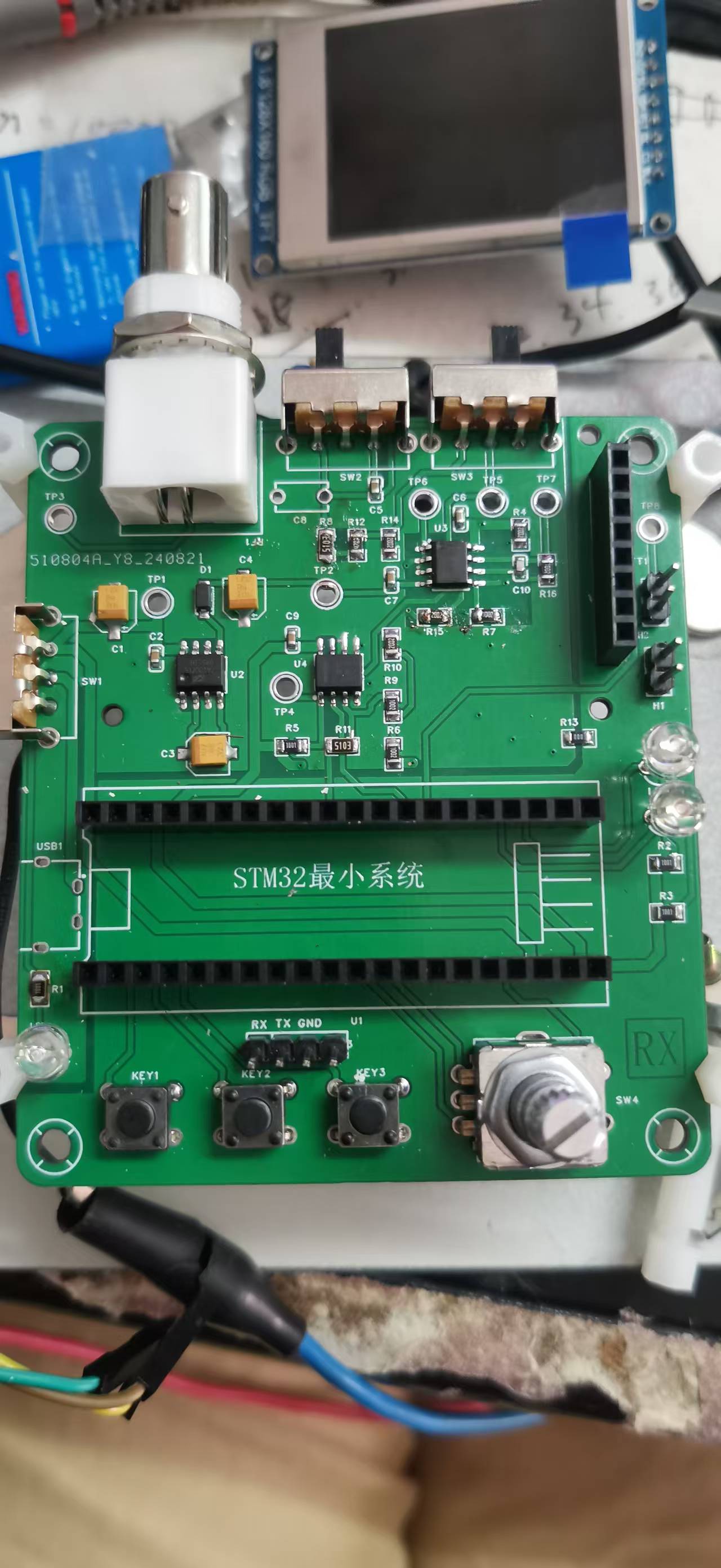
This is the soldered PCB; everything except the interface connectors is now surface-mount.
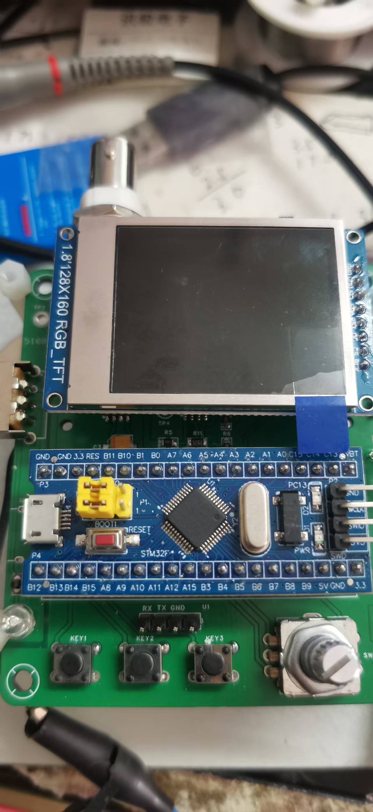
This is the assembled PCB. I added a programmable interface for direct serial programming.
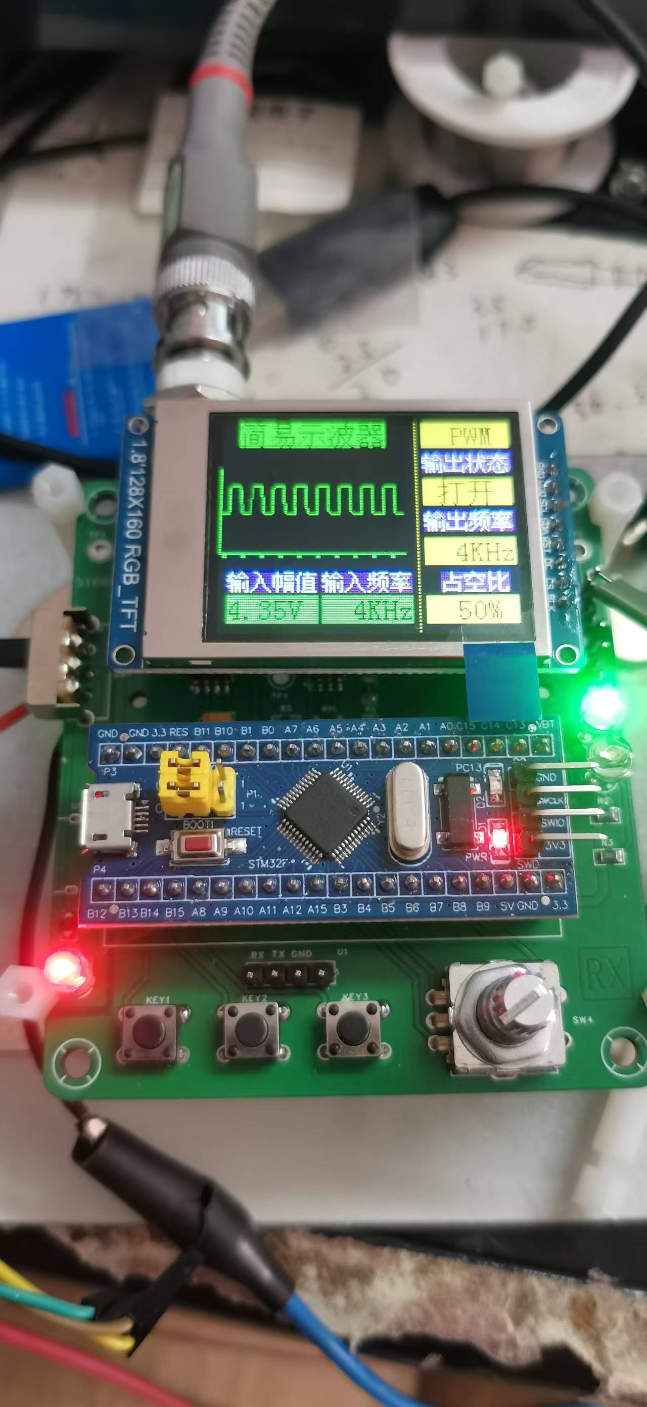
I wrote the program and tested its own signal generator. I tested
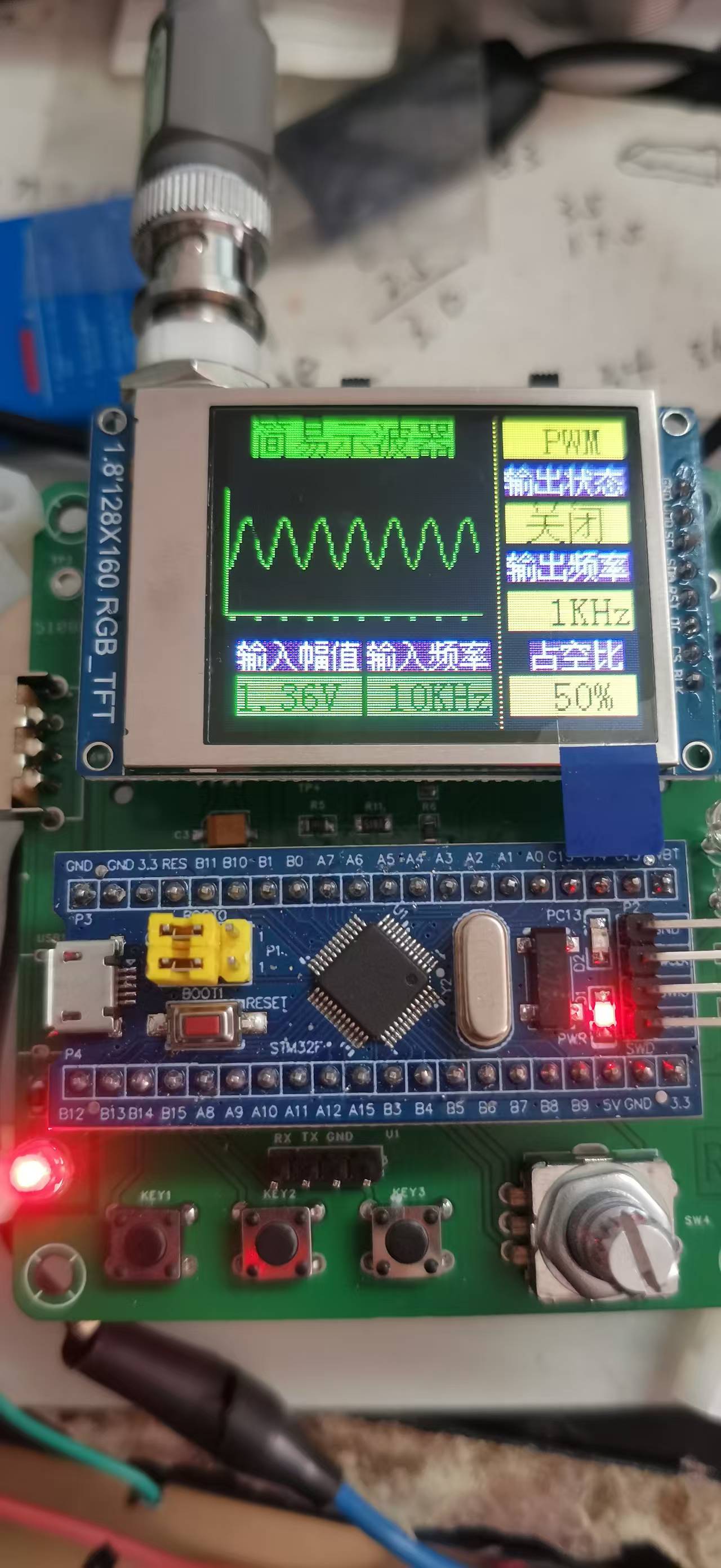
a 10kHz sine wave and

a 10kHz square wave.
The schematic wasn't modified; it shows a GD32E230, but the minimum system is the same for both STM and GD, only the program is different.
It's a small success, and JLCPCB is a great place to learn and improve. There were a few minor hiccups during the process. I used a heated soldering station, which resulted in some cold solder joints. During testing, there was only an interface without a waveform. I troubleshooted step-by-step from the input to the ADC, and once I solved the problem, the waveform appeared.
PDF_I also made a simple oscilloscope with my teacher.zip
Altium_I also built a simple oscilloscope following my teacher's instructions.zip
PADS_I also built a simple oscilloscope with my teacher.zip
BOM_I also built a simple oscilloscope with my teacher.xlsx
92396
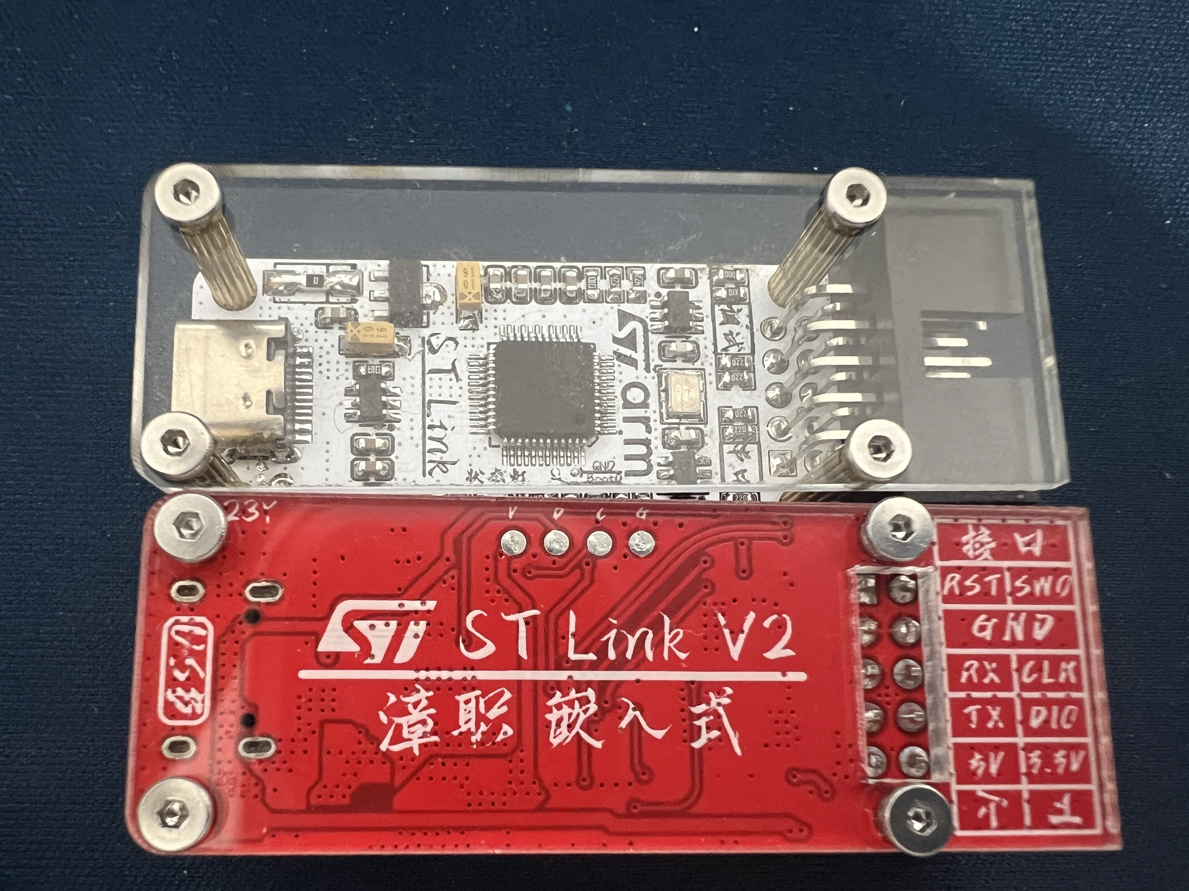
STlink V2-1
Added some protection circuitry, such as electrostatic discharge protection, while reducing cumbersome circuitry and eliminating unnecessary protection circuitry. Some packages were replaced; the circuit is now operational and must not be resold.
STLinkV2.J28.M18_Firmware.zip
PDF_STlink V2-1.zip
Altium_STlink V2-1.zip
PADS_STlink V2-1.zip
BOM_STlink V2-1.xlsx
92398
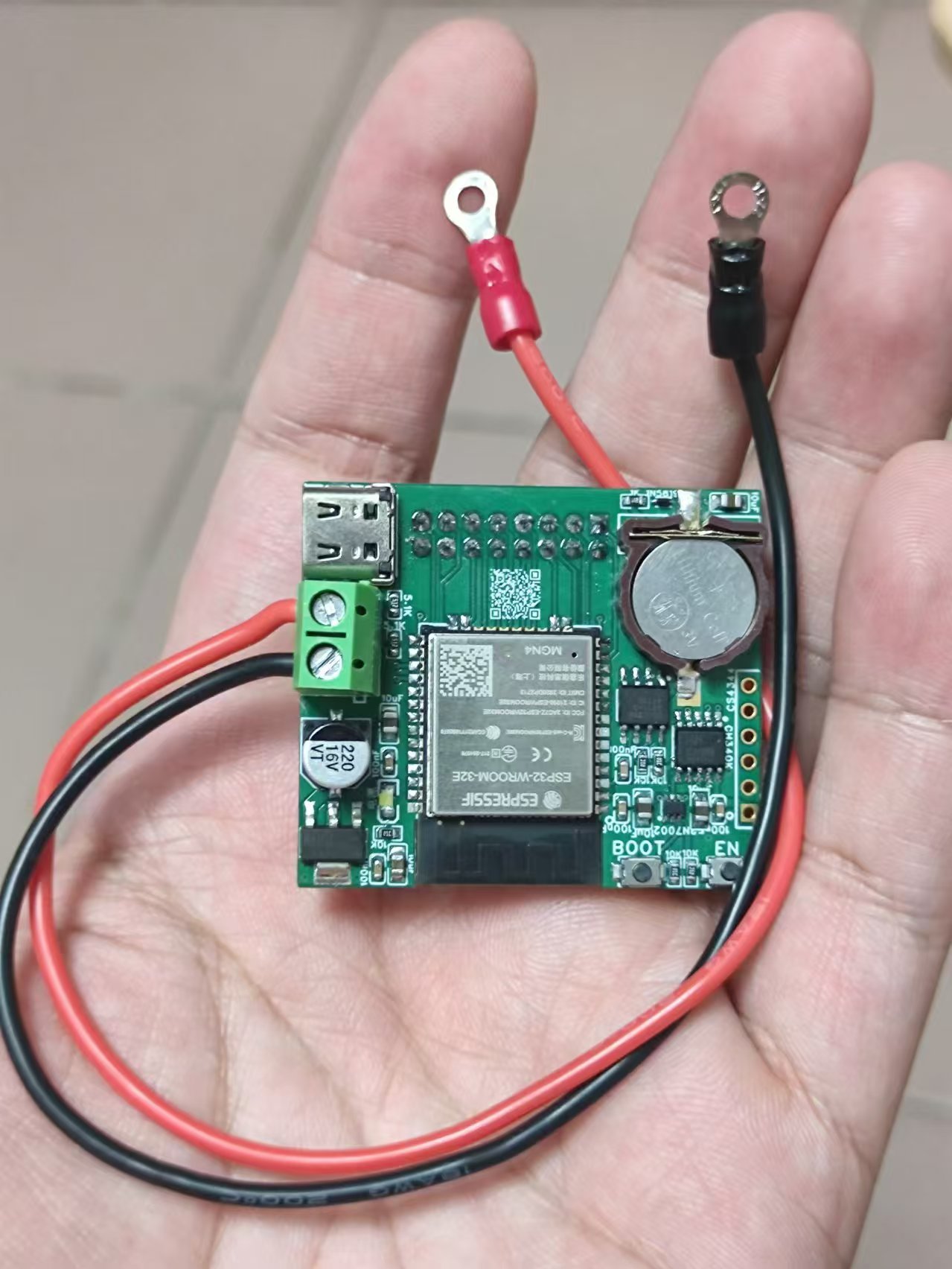
[Verified] BQ24640 - Supports 10A current step-down supercapacitor charger
The BQ24640-based step-down synchronous rectifier supercapacitor charger supports charging currents up to 10A, 5-28V input, and 2.1-28V output; with extremely low ripple, referencing the official EVM layout.
Introduction:
The BQ24640 is a 600kHz switching frequency, NMOS-NMOS synchronous buck topology supercapacitor charging controller. It supports 5-28V input voltage and 2.1-26V output voltage. It features CC-CV mode switching, supports 0V start-up charging for supercapacitors and other devices, supports charging currents up to 10A while maintaining efficiency above 90%, and supports high-temperature capacitor protection. In sleep mode, when the input voltage is removed, the capacitor current drops to as low as 15uA, reducing energy consumption.
Key Components/Replica Considerations:
1. I used the APG068N04G MOSFET, which costs about 60 cents each on Taobao. It has a 40V withstand voltage, an on-resistance of less than 6.8mΩ at 10Vgs, and a Ciss of 840pF. In actual testing, the on-resistance seemed a bit high, but the BQ24640 drove it reasonably well. A MOSFET with a larger Ciss could probably be used instead.
2. The surface-mount power inductor is a common 1770 package molded shielded surface-mount inductor found on Taobao, with a capacity of 6.8uH. While slightly bulky, its measured temperature rise at 9.5A is not high. In practical applications, if size is a concern, a smaller package can be used, and the inductance value can be appropriately reduced (e.g., using 4.7uH or 3.3uH) if ripple requirements are not high.
3. For 10A applications, the official recommendation is to use at least two 47uF capacitors in parallel at the input and output. The capacitor connected in series with a resistor acts as an RC filter to prevent high-voltage spikes from generated by the parasitic inductance of the circuit during power supply, which could damage the MOSFET and the main control IC. In the RC filter for the main control I2C power supply, the value of R should not be too large; the official recommendation is 4.7-30 ohms, and the package should be 0805 or 1206.
4. For the current sampling resistor, attention needs to be paid to power rating and temperature drift. Actual testing showed that for a 10A application, a 5mΩ, 2512 packaged current sampling resistor exhibits a significant temperature rise (reaching 60-70°C) at room temperature (23°C). This may cause malfunction when the current approaches the set overcurrent protection current; caution is advised.
5. For the MOSFET drive circuit, fast recovery diodes should be used. For this layout, a 2-ohm gate drive resistor is sufficient to obtain a good gate drive waveform. Other layouts require actual testing and adjustments.
Measured Data:
All test conditions for the following data are:
1. Room temperature 23°C
2. 12V to 5.2V, electronic load constant current mode
3. Test instruments:
Oscilloscope: Hantek DSO2C15
Power supply: ETM3010P
Electronic load: DCL8003+
Thermal imager: IRay C210
Due to limited personal time and expertise, it is impossible to control too many variables; therefore, this data is for reference only.
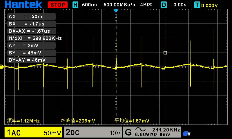
1. MOSFET gate drive waveform:
High-side MOSFET (to ground)

Low-side MOSFET (to ground)
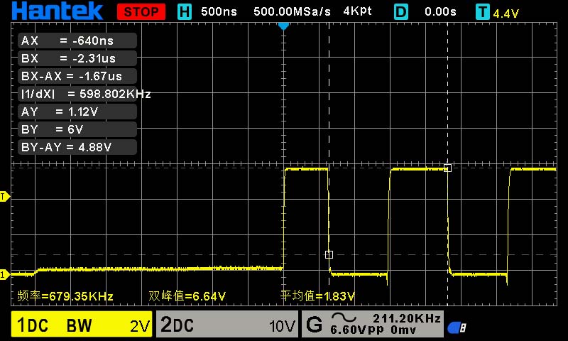
(Since the waveforms remain basically unchanged across power ranges, only one set is tested.)
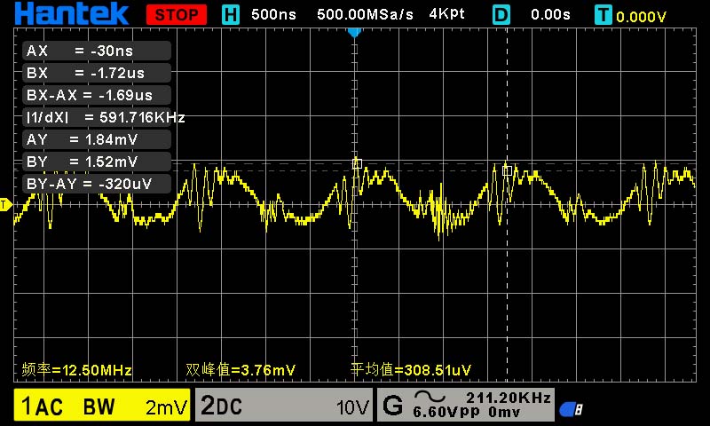
The following are constant current tests, showing the input and output voltages respectively. Some include thermal images after temperature stabilization.
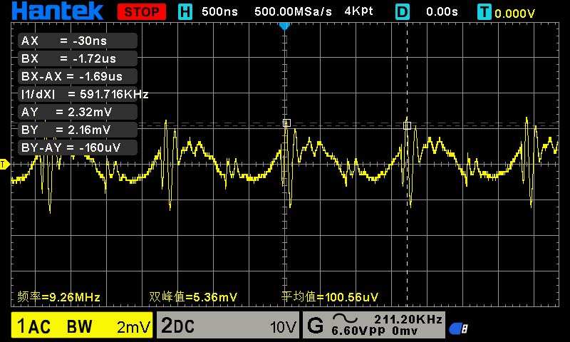
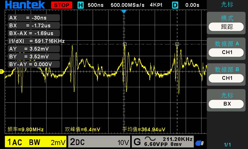
1A load constant current test:
Input:
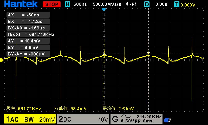
Output:
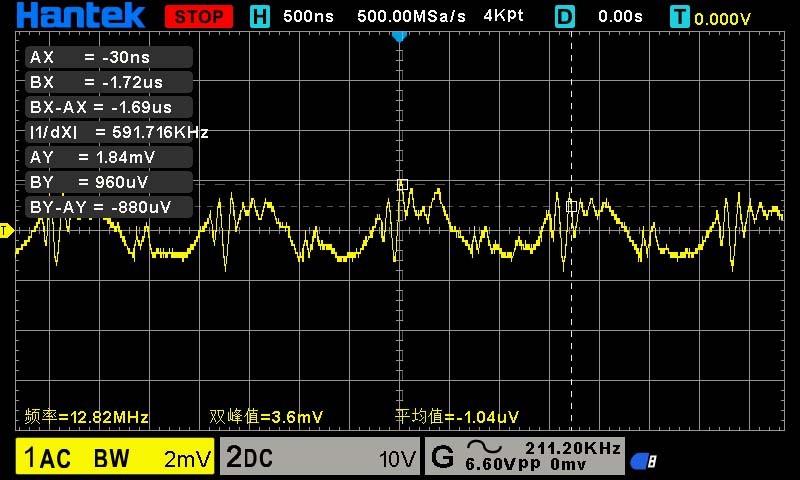
(These are indeed the values; it's not due to poor contact or something not being measured, because if there were poor contact and it wasn't measured, the induced noise would be much greater.)
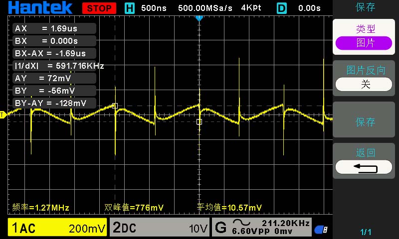
3A load:
Input: Output

:
5A load: Input:
Output

:

7A load:
Input:
Output:
8A load:
Input:

Output:
9A load:
Output:

9.5A load: Input
: Output

:

Long-term temperature rise:
Under a 9A load for 30 minutes, the upper transistor
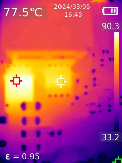
experienced the largest temperature rise: The upper transistor reached approximately 90 degrees Celsius, and the lower
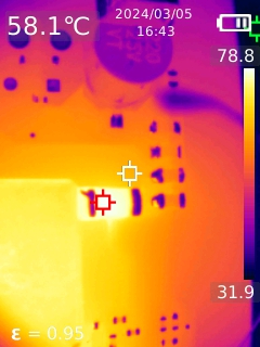
transistor reached approximately 77 degrees Celsius. The current sampling resistor also had a significant temperature, nearly 80 degrees Celsius. At 9.5A, the temperature drift of the sampling resistor increased further, causing the main controller to misjudge overcurrent and shut down, making testing impossible. For extended use, it is recommended to
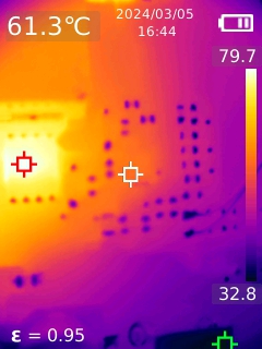
keep the current below 9A; the main controller IC remains relatively cool, at only around 61 degrees Celsius. It seems a transistor with a larger ciss and lower on-resistance could be used.
The inductor, being a metal, has a different emissivity, requiring thermocouple temperature measurement, which showed a temperature of around 65 degrees Celsius, relatively cool.
Another precaution:
When using constant current mode with an electronic load, if overcurrent protection is accidentally triggered, causing the IC to hiccup and start, the lower transistor and IC temperatures will rise rapidly during low-voltage output, potentially causing burnout!
PDF_[Verified] BQ24640 - Step-down Supercapacitor Charger Supporting 10A Current.zip
Altium_[Verified]BQ24640 - Step-down supercapacitor charger supporting 10A current.zip
PADS_[Verified]BQ24640 - Step-down supercapacitor charger supporting 10A current.zip
BOM_[Verified]BQ24640 - Step-down Supercapacitor Charger Supporting 10A Current.xlsx
92399
[Verified] 1.3-inch OLED (SH1106 driver, seven-wire SPI)
We found that bare OLED screens are relatively inexpensive, but modules are expensive. Therefore, we created a 1.3-inch OLED module (adapter board) to allow users to achieve OLED freedom (note that it only applies to 1.3-inch OLED screens driven by SH1106). SPI and IIC communication can be selected via R1 and R3.
The pins are compatible with commercially available seven-wire SPI OLED modules, and can be directly replaced.
The SH1106 driver is basically the same as the SSD1306, but the column start address needs to be changed to 0x02.
Updated September 7, 2024: If intermittent screen flickering, overheating, or no display occurs in this project or other designs derived from this project, first check if it is caused by poor soldering of the FPC cable. If this method is ineffective, **consider replacing all existing capacitors with capacitors with higher voltage ratings. A voltage rating of 16V or higher is recommended.**
```
/**
* ************************************************************************************************
* @brief Send buffer
* @note
* - Low column start address is 0x02 when using a 1.3-inch OLED display
* - Low start address is 0x00 when using a 0.96-inch OLED display
* ****************************************************************************************
*/
// Update video memory to OLED
void OLED_Refresh(void)
{
u8 i, n;
for (i = 0; i
PDF_【Verified】1.3-inch OLED (SH1106 driver, seven-wire SPI).zip
Altium_【Verified】1.3-inch OLED (SH1106 driver, seven-wire SPI).zip
PADS_【Verified】1.3-inch OLED (SH1106 driver, seven-wire SPI).zip
BOM_【Verified】1.3-inch OLED (SH1106 driver, seven-wire SPI).xlsx
92400
electronic


 京公网安备 11010802033920号

 HEDS-5645-H14


