I. Project Introduction
This project is a voltage and current meter developed using the LCSC CW32F030C8T6 development board. Its features include:
adopting the LCSC development board + expansion board design concept, using plug-in components for easier learning and even beginners can easily complete the soldering;
using the domestic Wuhan Xinyuan Semiconductor CW32 as the main controller;
high integration and strong practicality, it can be used as a desktop instrument after completion;
the project includes circuit design instruction, PCB design, code programming learning, and the cultivation of engineers' debugging skills, providing a comprehensive training experience.
Using JLCPCB's color silkscreen printing for PCB fabrication allows you to unleash your creativity and satisfy your display desires.

Key advantages of the CW32 in this project include :
Wide operating temperature range: -40℃ to 105℃;
Wide operating voltage: 1.65V to 5.5V (STM32 only supports 3.3V systems);
Strong anti-interference: HBM ESD 8KV; All ESD reliability reaches the highest international standard level (STM32 ESD 2KV);
Better ADC: 12-bit high-speed ADC, achieving ±1.0LSB INL 11.3ENOB; Multiple Vref reference voltages... (STM32 only supports VDD=Vref);
Stable and reliable eFLASH technology: Flash0 waiting.
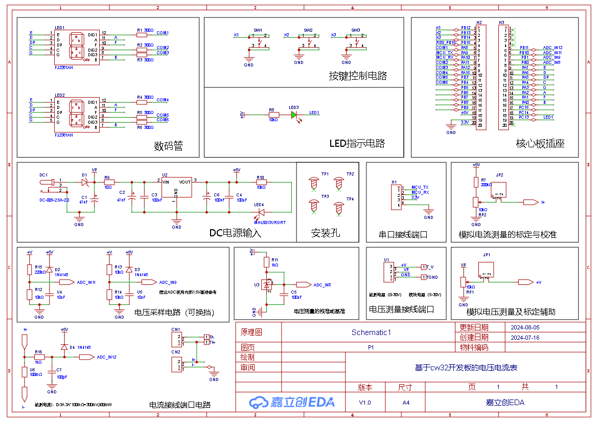
II. Schematic Design Description
1. Schematic Diagram
2. Preview Diagram

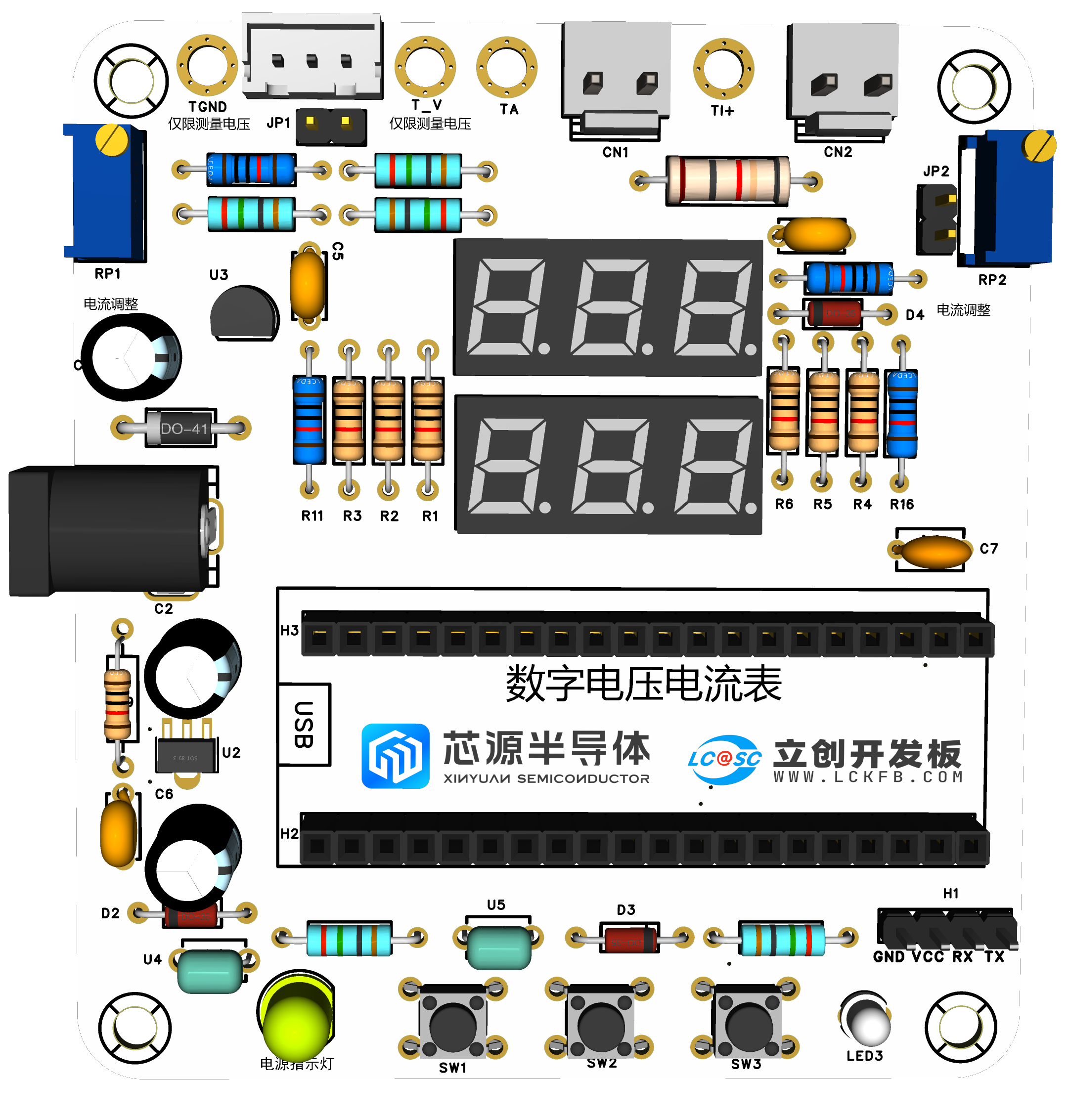

III. Physical Object Display

IV. PCB Design Description
Plug-in design, simple wiring, easy soldering, suitable for beginners.
V. Software Description
1. LED Indicator
System: Two LED indicators are designed, one power indicator LED4 and one indicator LED1 for free programming testing, using red and green designs respectively for easy differentiation.


Relevant code:
/*
Function content: Initializes the LED pins.
Function parameters: None.
Return value: None.
*/
void Init_Led_GPIO(void)
{
GPIO_InitTypeDefGPIO_InitStruct; // GPIO initialization structure
__RCC_GPIOC_CLK_ENABLE(); // Enable GPIO clock
GPIO_InitStruct.Pins = GPIO_PIN_13; // GPIO pins
GPIO_InitStruct.Mode = GPIO_MODE_OUTPUT_PP;// Push-pull output. GPIO modes include analog input, digital input, digital pull-up input, digital pull-down input, digital push-pull output, and digital open-drain output modes.
GPIO_InitStruct.Speed = GPIO_SPEED_HIGH; // High output speed, with both high and low speeds
GPIO_InitStruct.IT = GPIO_IT_NONE; // We need GPIO output, so we disable interrupts
GPIO_Init(CW_GPIOC, &GPIO_InitStruct); // Initialize
printf("[Init_Led_GPIO]
");
}
/*
Function content: Open LED
Function parameters: None
Return value: None
*/
void Open_Led(GPIO_TypeDef *GPIOx, uint16_t GPIO_Pins)
{
// Output low level
GPIO_WritePin(GPIOx, GPIO_Pins, GPIO_Pin_RESET);
printf("[RESET]
");
}
/*
Function content: Close LED
Function parameters: None
Return value: None
*/
void Close_Led(GPIO_TypeDef *GPIOx, uint16_t GPIO_Pins)
{
// Output high level
GPIO_WritePin(GPIOx, GPIO_Pins, GPIO_Pin_SET);
printf("[SET]
");
}
/*
Function content: Toggle LED
Function parameters: None
Return value: None
*/
void Toggle_LED(GPIO_TypeDef *GPIOx, uint16_t GPIO_Pins)
{
// Toggle level
GPIO_TogglePin(GPIOx,GPIO_Pins);
printf("[Toggle]
");
}
//==================================
#include "board.h" #include "stdio.h" #include "bsp_uart.h" #include "led.h" #include "key.h"
int32_t main(void)
{
board_init(); // The development board is initialized with
`uart1_init(115200);` // Serial port 1 baud rate 115200 `
while(1)
{
Init_Led_GPIO();
Toggle_LED(CW_GPIOC,GPIO_PIN_13);
delay_ms(500);
}`
2.
Button Detection:

There are multiple design options for button control circuits. Thanks to the CW32's internal I/O ports which can be configured with pull-up and pull-down resistors, the button control circuit on the chip's periphery does not require such configuration. One end of the button is connected to the MCU's I/O, and the other end is grounded. When the button is pressed, the I/O is pulled low.
#include "board.h"
#include "stdio.h"
#include "key.h "
#include "led.h"
uint8_t Flag_Key = 0; // Key flag
uint8_t Flag_LED = 0; // LED display flag
/*
Function content: Initializes the pins used by KEY
Function parameters: None
Return value: None
*/
void Init_Key_GPIO(void)
{
GPIO_InitTypeDefGPIO_InitStruct; // GPIO initialization structure
__RCC_GPIOB_CLK_ENABLE(); // Enable GPIO clock
GPIO_InitStruct.Pins = GPIO_PIN_14; // GPIO pins
GPIO_InitStruct.Mode = GPIO_MODE_INPUT_PULLUP;// Pull-up input, GPIO modes include analog input, digital input, digital pull-up input, digital pull-down input, digital push-pull output, and digital open-drain output modes.
GPIO_InitStruct.IT = GPIO_IT_NONE; // We need GPIO output, so we disable interrupts
GPIO_Init(CW_GPIOB, &GPIO_InitStruct); // Initialize
printf("[Init_Key_GPIO]
");
}
/*
Function content: Key scan
function Parameters: None
Return value: None
*/
void Key_Scan(void) // Key scan
{
if(GPIO_ReadPin(CW_GPIOB,GPIO_PIN_14) == GPIO_Pin_RESET) // Check if PB2 is high
{
Flag_Key = 1;
}
if(Flag_Key) // Then check the flag bit
{
if(GPIO_ReadPin(CW_GPIOB,GPIO_PIN_14) == GPIO_Pin_SET) // If the button has been released
{
Flag_Key = 0; // Clear the flag bit and wait for the next button detection
Flag_LED = 1 - Flag_LED; //The value of the LED display flag is changed when the button is pressed, and the LED is controlled by the display flag.
}
}
}
void LED_Ctrl(void)
{
if(Flag_LED == 1) Open_Led(CW_GPIOC,GPIO_PIN_13); //On
else Close_Led(CW_GPIOC,GPIO_PIN_13); //Off
}
//==================================
#include "board.h"#include "stdio.h"#include "bsp_uart.h"#include "led.h"#include "key.h"
int32_t main(void)
{
board_init(); // Initialize the development board
uart1_init(115200);// Serial port 1 baud rate 115200
Init_Led_GPIO();
Init_Key_GPIO();
while(1)
{
Key_Scan();
LED_Ctrl();
}
}
3. Digital Tube Driver
This project uses two 0.28-inch 3-digit common cathode digital tubes as display units, directly driven by the microcontroller pins. Compared to displays, digital tubes have better recognition in complex environments. The brightness of the digital tubes can be increased by using smaller current-limiting resistors according to the actual usage environment. Furthermore, digital tubes have better mechanical properties and are not easily damaged by external forces like displays. They are widely used in industrial applications requiring stability and reliability. From the perspective of learning from development boards, it is easier to learn electronic measurement principles and related development in a targeted manner.
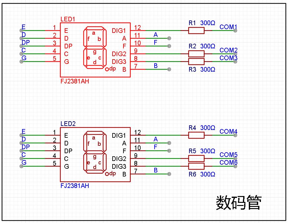
In this project, after actual testing, the current-limiting resistors (R1~R6) of the digital tubes were configured to 300Ω. The corresponding brightness, whether for red or blue digital tubes, has good recognition and is soft and not dazzling.
Digital Tube Driving Principle:
The driving principle of digital tubes mainly involves controlling the switching state of each segment of the digital tube to display numbers, letters, or symbols. The following is a detailed explanation of the driving principle:
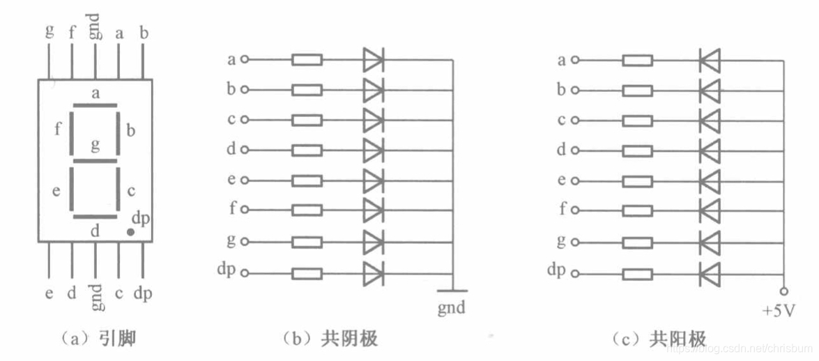
Basic structure of a digital tube:
A digital tube typically consists of seven or eight LED segments (eight segments in this project). Each segment represents a part of the digital tube and can display numbers 0-9, letters AF, etc.
Digital tubes come in two types: common cathode and common anode. The difference lies in whether the common terminal COM (the end connecting all LEDs) is connected to the negative or positive terminal of the power supply.
Driving method:
Segment Selection: Displaying the desired numbers or characters is achieved by controlling the on/off state of each segment of the digital tube. Each segment corresponds to a control signal; when the control signal is on, the segment lights up, and vice versa. (a, b, c, d, e, f, g, dp)
Bit Selection: Selecting the digital tube to be displayed is achieved by controlling its bit lines. Bit line control sets the bit line of the desired digital tube to a high level and the bit lines of other digital tubes to a low level. By continuously switching the state of the bit lines, display switching between multiple digital tubes can be achieved.
Driver Circuit:
The digital tube driver circuit can be implemented using hardware circuits, such as integrated circuits like digital signal processors (DSPs), microcontrollers (MCUs), or shift registers to generate control signals suitable for the LEDs.
These control signals can be in the form of pulse width modulation (PWM) signals, serial data signals, etc. By controlling the frequency, width, and amplitude of these signals, the brightness of the digital tube can be controlled, thereby displaying the desired numbers or letters.
Software Control:
In addition to hardware driver circuits, the digital tube can also be driven by software. By programming and generating control signals suitable for the digital tube, more flexible and complex display effects can be achieved, such as scrolling or alternating display of numbers.
Driving common cathode and common anode digital tubes:
For common cathode digital tubes, the common cathode pin is connected to the negative terminal of the power supply, and the control pin is connected to the output pin of the control chip. When a number needs to be displayed, the control chip outputs the corresponding encoded signal to the control pin, causing the corresponding LED segment to light up.
For common anode digital tubes, the working principle is similar to that of common cathode digital tubes, except that the common anode pin is connected to the positive terminal of the power supply, and the control pin is connected to the output pin of the control chip.
Encoded display:
In order for the digital tube to display the corresponding number or character, the segment data port must output the corresponding character code. For example, to display the number "0", the character code for a common anode digital tube is 11000000B (i.e., C0H), while the character code for a common cathode digital tube is 00111111B (i.e., 3FH). The specific code depends on the actual digital tube.
Dynamic and static display:
Digital tubes can use either static or dynamic display methods. In static display, each of the eight segments of a digital tube is connected to an 8-bit I/O port address. As long as the I/O port outputs a segment code, the corresponding character is displayed and remains unchanged. Dynamic display, on the other hand, lights up each segment of the digital tube one by one in turn, achieving simultaneous visual display through rapid switching.
In summary, the driving principle of a digital tube is to control the switching state of each segment to display numbers, letters, or symbols, and to achieve display switching between multiple digital tubes through segment selection and digit selection. Simultaneously, the driving of the digital tubes can be implemented through hardware circuits or software control, and common cathode or common anode digital tubes can be selected as needed.
This project actually uses dynamic scanning display to drive the digital tubes.
Calculating the required current for the digital tubes
: Since this project uses dynamic scanning display to drive the digital tubes, at any given time, only a maximum of eight segments of the digital tubes (or LEDs) can be lit, or in other words, only one digit can be lit. According to the design, the required driving current is approximately 11mA (IO port high-level voltage 3.3V ÷ 300Ω).
At this point, it is important to ensure that the selected MCU has sufficient current-pull/sinking capability.
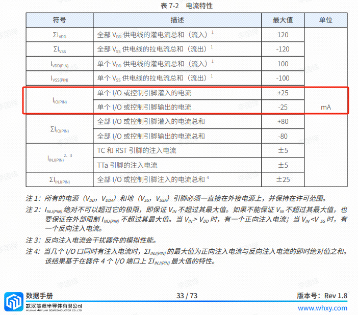
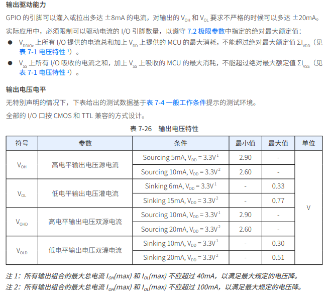
Analysis of the datasheet shows that the CW32 has no problems, but some chips do not.
#include "board.h"
#include "stdio.h"
#include "Seg_Display.h"
/* Common cathode seven-tube encoding table:
0x3f 0x06 0x5b 0x4f 0x66 0x6d 0x7d 0x07 0x7f 0x6f
0 1 2 3 4 5 6 7 8 9
0xbf 0x86 0xdb 0xcf 0xe6 0xed 0xfd 0x87 0xff 0xef
0. 1. 2. 3. 4. 5. 6. 7. 8. 9. */
//0x3f, 0011 1111; 0x5b 0101 1011
uint8_t Seg_Table[20] = {0x3f, 0x06, 0x5b, 0x4f, 0x66, 0x6d, 0x7d, 0x07, 0x7f, 0x6f,
0xbf, 0x86, 0xdb, 0xcf, 0xe6, 0xed, 0xfd, 0x87, 0xff, 0xef};
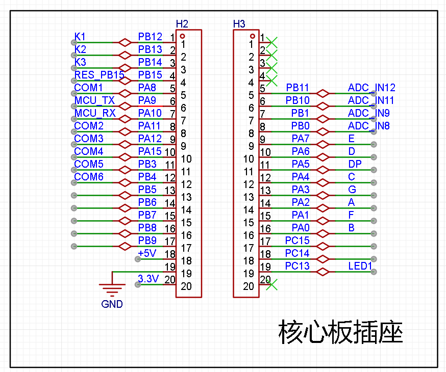
void Seg_Configuration(void) //Find the schematic and initialize the relevant pins of the digital tube
{
__RCC_GPIOA_CLK_ENABLE(); //Turn on the clock of GPIOA
__RCC_GPIOB_CLK_ENABLE(); //Turn on the clock of GPIOB
GPIO_InitTypeDef GPIO_InitStruct;
GPIO_InitStruct.Pins = GPIO_PIN_2 | GPIO_PIN_0 | GPIO_PIN_4 | GPIO_PIN_6 | GPIO_PIN_7 | GPIO_PIN_1 | GPIO_PIN_3 | GPIO_PIN_5 | GPIO_PIN_8 | GPIO_PIN_11 | GPIO_PIN_12 | GPIO_PIN_15;
//A:PA02;B:PA00;C:PA04;D:PA06;E:PA07;F:PA01;G:PA03;DP:PA05;
//COM1:PA08;COM2:PA11;COM3:PA12;COM4:PA15;COM5:PB03;COM6:PB04;
GPIO_InitStruct.Mode = GPIO_MODE_OUTPUT_PP;
GPIO_InitStruct.IT = GPIO_IT_NONE;
GPIO_InitStruct.Speed = GPIO_SPEED_HIGH;
GPIO_Init(CW_GPIOA, &GPIO_InitStruct);
GPIO_InitStruct.Pins = GPIO_PIN_3 | GPIO_PIN_4; //COM5:PB03;COM6:PB04
GPIO_InitStruct.Mode = GPIO_MODE_OUTPUT_PP;
GPIO_InitStruct.IT = GPIO_IT_NONE;
GPIO_InitStruct.Speed = GPIO_SPEED_HIGH;
GPIO_Init(CW_GPIOB, &GPIO_InitStruct);
}
void Seg_Dis(uint8_t Pos,uint8_t Num)
{
//The voltmeter and ammeter have two digital tubes. We will use the upper tube in this case, so the lower digital tube is turned off.
GPIO_WritePin(CW_GPIOA,GPIO_PIN_15,GPIO_Pin_SET); //PA15,COM4
GPIO_WritePin(CW_GPIOB,GPIO_PIN_3,GPIO_Pin_SET); //PB03,COM5
GPIO_WritePin(CW_GPIOB,GPIO_PIN_4,GPIO_Pin_SET); //PB04,COM6
int i;
uint8_t Dis_Value = Seg_Table[Num];
for(i = 0; i
{
switch(i)
{
case 0:
GPIO_WritePin(CW_GPIOA,GPIO_PIN_2,(Dis_Value >> i) & 0x01); //PA02,A
break;
case 1:
GPIO_WritePin(CW_GPIOA,GPIO_PIN_0,(Dis_Value >> i) & 0x01); //PA00,B
break;
case 2:
GPIO_WritePin(CW_GPIOA,GPIO_PIN_4,(Dis_Value >> i) & 0x01); //PA04,C
break;
case 3:
GPIO_WritePin(CW_GPIOA,GPIO_PIN_6,(Dis_Value >> i) & 0x01); //PA06,D
break;
case 4:
GPIO_WritePin(CW_GPIOA,GPIO_PIN_7,(Dis_Value >> i) & 0x01); //PA07,E
break;
case 5:
GPIO_WritePin(CW_GPIOA,GPIO_PIN_1,(Dis_Value >> i) & 0x01); //PA01,F
break;
case 6:
GPIO_WritePin(CW_GPIOA,GPIO_PIN_3,(Dis_Value >> i) & 0x01); //PA03,G
break;
case 7:
GPIO_WritePin(CW_GPIOA,GPIO_PIN_5,(Dis_Value >> i) & 0x01); //PA05,DP
break;
default:
break;
}
}
switch(Pos)
{
case 1:
GPIO_WritePin(CW_GPIOA,GPIO_PIN_8,GPIO_Pin_RESET); //PA08,COM1
GPIO_WritePin(CW_GPIOA,GPIO_PIN_11,GPIO_Pin_SET); //PA11,COM2
GPIO_WritePin(CW_GPIOA,GPIO_PIN_12,GPIO_Pin_SET); //PA12,COM3
break;
case 2:
GPIO_WritePin(CW_GPIOA,GPIO_PIN_8,GPIO_Pin_SET); //PA08,COM1
GPIO_WritePin(CW_GPIOA,GPIO_PIN_11,GPIO_Pin_RESET); //PA11,COM2
GPIO_WritePin(CW_GPIOA,GPIO_PIN_12,GPIO_Pin_SET); //PA12,COM3
break;
case 3:
GPIO_WritePin(CW_GPIOA,GPIO_PIN_8,GPIO_Pin_SET); //PA08,COM1
GPIO_WritePin(CW_GPIOA,GPIO_PIN_11,GPIO_Pin_SET); //PA11,COM2
GPIO_WritePin(CW_GPIOA,GPIO_PIN_12,GPIO_Pin_RESET); //PA12,COM3
break;
default:
break;
}
}
//==============================
#include "main.h"
int main()
{
RCC_Configuration();
Seg_Configuration();
Seg_Dis(1,8);
Seg_Dis(2,8);
Seg_Dis(3,8);
while(1)
{
}
}
void RCC_Configuration(void)
{
RCC_HSI_Enable(RCC_HSIOSC_DIV6);
/* 1. Set the division coefficients of HCLK and PCLK */
RCC_HCLKPRS_Config(RCC_HCLK_DIV1);
RCC_PCLKPRS_Config(RCC_PCLK_DIV1);
/* 2. Enable PLL and multiply the frequency to 64MHz through HSI */
RCC_PLL_Enable(RCC_PLLSOURCE_HSI, 8000000, 8);
// PLL output frequency 64MHz
/*
__RCC_FLASH_CLK_ENABLE();
FLASH_SetLatency(FLASH_Latency_3);
/* 3. Switch the clock to PLL */
RCC_SysClk_Switch(RCC_SYSCLKSRC_PLL);
RCC_SystemCoreClockUpdate(64000000);
}
In the previous desktop thermometer and hygrometer training camp, two 3-digit common cathode LED displays were also used, but that project used three SN74HC595PWR modules to drive them.
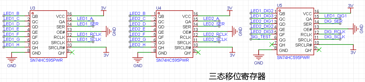
For details, please refer to the project tutorial: https://www.yuque.com/wldz/jlceda/govtkghsdyrs9v3t
4. In actual program writing, I used a time-slice polling-based task scheduling method.
Time-slice polling is a program architecture somewhere between a foreground/background sequential structure and an operating system. Time-slice polling actually implements multi-task management within a foreground/background sequential structure. Its core is to use a timer as a time base; when a task's time slice expires, the task is executed once. Each task has its own time slice and is executed according to the time slice interval, effectively making the tasks independent of each other. There are many program architectures online that use object-oriented programming, which are more suitable for actual engineering. See [4] for details. The following program model is to make the principle of time-slice polling more intuitive. The program model is as follows:
#define TASK1_TIME_SLICE 10
#define TASK2_TIME_SLICE 20
void TimerX_handler(void)
{
ms_cnt++;
} int main
(void)
{
while(1)
{
if(ms_cnt%TASK1_TIME_SLICE==0)
task1(); if(ms_cnt% TASK2_TIME_SLICE
==0)
task2();
} return
0;
}
// = ... "TimeBase.h" #include "led.h" #include "key.h" /************************************************ Function Name: TimeSlice10MSTask Function: 10ms timer Function Parameters: void Return Value: void Author: *************************************************/ void TimeSlice10MSTask(void) { } /************************************************ Function Name: TimeSlice50MSTask Function: 50ms timer Function Parameters: void Return Value: void Author: *************************************************/ void TimeSlice50MSTask(void) { } /************************************************ Function Name: TimeSlice100MSTask Function: 100ms timer Function Parameters: void Return Value: void Author: *************************************************/ void TimeSlice100MSTask(void) {
}
/************************************************
Function Name: TimeSlice200MSTask
Function: 200ms timer Function
Parameters: void
Return Value: void
Author:
*************************************************/
void TimeSlice200MSTask(void)
{
}
/************************************************
Function Name: TimeSlice500MSTask
Function: 500ms timer Function
Parameters: void
Return Value: void
Author:
*****************************************************/
void TimeSlice500MSTask(void)
{
oBigTimeSlice.bTaskFlag[TIMESLICE_500MS]=FlagTrue;
Init_Led_GPIO();
Init_Key_GPIO();
Key_Scan();
LED_Ctrl();
}
/************************************************
Function Name: TimeSlice1STask
Function: 1s timer Function
Parameters: void
Return Value: void
Author:
**************************************************/
void TimeSlice1STask(void)
{
// oBigTimeSlice.bTaskFlag[TIMESLICE_1S]=FlagTrue;
// Init_Led_GPIO();
// Toggle_LED(CW_GPIOC,GPIO_PIN_13);
// delay_ms(500);
}
/************************************************
Function Name: TimeSlice5STask
Function: 5s timer Function
Parameters: void
Return Value: void
Author:
*****************************************************/
void TimeSlice5STask(void)
{
}
/************************************************
Function Name: TimeSlice1MINTask
Function: 1min timer Function
Parameters: void
Return Value:
void Author:
*************************************************/
void TimeSlice1MINTask(void)
{
}
/************************************************
Function Name: TimeSliceTaskSchedule
Function: Time-slice polling
Parameters: void
Return Value: void
Author:
*************************************************/
void TimeSliceTaskSchedule(void)
{
if (oSmallTimeSlice.bTaskFlag[TIMESLICE_10MS]==FlagTrue)
{
oSmallTimeSlice.bTaskFlag[TIMESLICE_10MS] = FlagFalse;
TimeSlice10MSTask();
}
if (oSmallTimeSlice.bTaskFlag[TIMESLICE_50MS]==FlagTrue)
{
oSmallTimeSlice.bTaskFlag[TIMESLICE_50MS] = FlagFalse;
TimeSlice50MSTask();
}
if (oSmallTimeSlice.bTaskFlag[TIMESLICE_100MS]==FlagTrue)
{
oSmallTimeSlice.bTaskFlag[TIMESLICE_100MS] = FlagFalse;
TimeSlice100MSTask();
}
if (oSmallTimeSlice.bTaskFlag[TIMESLICE_200MS]==FlagTrue)
{
oSmallTimeSlice.bTaskFlag[TIMESLICE_200MS] = FlagFalse;
TimeSlice200MSTask();
}
if (oBigTimeSlice.bTaskFlag[TIMESLICE_500MS]==FlagTrue)
{
oBigTimeSlice.bTaskFlag[TIMESLICE_500MS] = FlagFalse;
TimeSlice500MSTask();
}
if (oBigTimeSlice.bTaskFlag[TIMESLICE_1S]==FlagTrue)
{
oBigTimeSlice.bTaskFlag[TIMESLICE_1S] = FlagFalse;
TimeSlice1STask();
}
if (oBigTimeSlice.bTaskFlag[TIMESLICE_5S]==FlagTrue)
{
oBigTimeSlice.bTaskFlag[TIMESLICE_5S] = FlagFalse;
TimeSlice5STask();
}
if (oBigTimeSlice.bTaskFlag[TIMESLICE_1MIN]==FlagTrue)
{
oBigTimeSlice.bTaskFlag[TIMESLICE_1MIN] = FlagFalse;
TimeSlice1MINTask();
}
}
TimeBase.c
#include "TimeBase.h"
uint8_t C_rSmallTickCountMax[SMALLTIMESLICE_COUNT_MAX]={10,50,100,200};uint32_t C_wBigTickCountMax[BIGTIMESLICE_COUNT_MAX]={500,1000,5000,60000};
volatile TSmallTimeSlice oSmallTimeSlice; volatile TBigTimeSlice oBigTimeSlice;
void TimeBaseInit(void){ uint8_t i; for (i=0;i { oSmallTimeSlice.rTickCount[i] = 0; oSmallTimeSlice.bTaskFlag[i] = FlagTrue; } for (i=0;i { oBigTimeSlice.wTickCount[i] = 0; oBigTimeSlice.bTaskFlag[i] = FlagTrue; }}
/** * @brief time base task */void TimeBaseSchedule(){ uint8_t i;
for (i=0;i { if (oSmallTimeSlice.rTickCount[i] { oSmallTimeSlice.rTickCount[i]++; } else { oSmallTimeSlice.bTaskFlag[i] = FlagTrue; oSmallTimeSlice.rTickCount[i] = 1; } }
for (i=0;i { if (oBigTimeSlice.wTickCount[i] { oBigTimeSlice.wTickCount[i]++; } else { oBigTimeSlice.bTaskFlag[i] =FlagTrue; oBigTimeSlice.wTickCount[i] = 1; } }}
6. Demonstration video


 京公网安备 11010802033920号

 UPD434016ALE


