"Project Introduction
——————————————————————————————————————————————————————————————————
This design realizes flexible and ever-changing user event input requirements, making user input simpler, more convenient, more efficient, and with unlimited possibilities. The design and development mainly includes the following parts:
circuit design implementation,
development and implementation of low-power Bluetooth BLE software, and
development and implementation of host computer PC software.
01 Project Background"
————————————————————————————————————————————————————————————————
Due to the recent sharp drop in temperature in Shenzhen, this open-source project was able to be showcased (it was too cold this weekend, and I didn't want to go anywhere, so I just stayed home and did nothing; so, I started
to contemplate life; time flies, and it's already December 24, 2023, and the year is almost over! We can't just do nothing, right? Thinking about it, that
would be such a waste of life. Shouldn't we do something meaningful? So I remembered a project I did before, and I wanted to organize it and share it with everyone for discussion and learning, contributing to the development of domestic products. Let's make domestic
products better and better, and more and more open. As long as we don't admit defeat, no one can defeat us. The same goes for chips. Haha, I'm getting a little tipsy.
02 Project Highlights
————————————————————————————————————————————————————————————————
1. Multiple connection methods: This design can connect to a computer via USB cable (HID) or Bluetooth Low Energy (BLE).
2. Microsoft Swift-Pair: When using Bluetooth Low Energy (BLE) to connect to a computer, this design also features Microsoft's Swift-Pair function, enabling rapid Bluetooth pairing and making Bluetooth
connection and interaction simple and fast.
Note: The following Bluetooth configuration items need to be configured on the computer side.

3. Implements various configurable and rich key combinations, such as various common keyboard key combinations, time delays between key series, and even combinations of mouse and keyboard input,
making user input simpler, more convenient, more efficient, and more possible. It can be effectively used for office work, games, etc.
4. Simple, flexible, and visual PC-side host computer configuration tool.
5. This design implements Microsoft's Surface Dial function, giving it more input methods and enriching user operability.
6. All software and hardware are open source.
03 Open Source Project Description
————————————————————————————————————————————————————————————————
This project consists of the following three parts
: 1. Macro keyboard entity, consisting of 6 keys, a pulse-coded knob, and a USB interface, etc., including
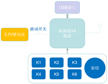
hardware block

diagram and 3D preview
. 2. Host computer configuration tool, which interacts with the macro keyboard entity via USB HID; the host computer is developed using the Electron software framework, primarily considering cross-platform compatibility.

PC host computer preview
. 3. Low-power Bluetooth software, the controller used in this design is the domestic Bluetooth chip AC6321A, which realizes key scanning and wired/wireless BLE transmission of key events.
04 Hardware Introduction
————————————————————————————————————————————————————————————————
1. Board Resources and Dimensions


2. Main Control Chip AC6321A
The AC6321A is a Bluetooth chip from Jerry, V5.3+BR+EDR+BLE The specification is open-sourced by Jerry on Gitee, where you can find further details, including the SDK,
related development documentation, and development environment. Some schematics are shown below:

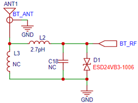
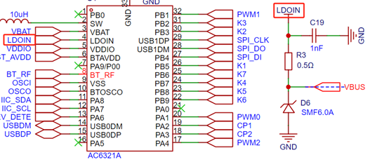
Main control chip schematic;
RF circuit: Depending on the actual circuit and structural layout, the capacitors and inductors in these RF circuits need adjustment, as this affects the RF receiving sensitivity and transmitting efficiency.
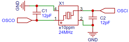
Clock circuit: Provides a 24MHz clock signal to the chip. The values of the two load capacitors need to be selected according to the crystal oscillator datasheet; in this design, 12pF is selected, with a crystal oscillator error range of ±10ppm.
Battery circuit: Relatively simple, consisting of a 2.0mm 2-pin socket and a toggle switch forming

the chip's 1.3V core power supply circuit. This part consists of a 10uH power inductor, two filter capacitors, and the chip's internal DC-to-DC power supply.

Battery charging circuit: This design uses the chip's internal battery charging management LDO to manage battery charging, providing 4.2V and a maximum charging current of 200mA.
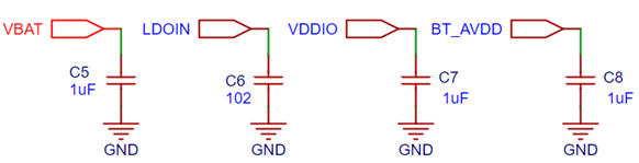
Power supply filtering circuit
3. The USB interface circuit
consists of a Type-C interface and two 5.1k resistors connected to ground at the CC port. For a
detailed explanation of why 5.1k resistors are used instead of other values, please refer to the USB Chinese website for a detailed description of the Type-C section.

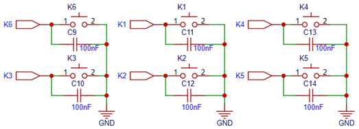
4. The button circuit
consists of six buttons and a filter capacitor.
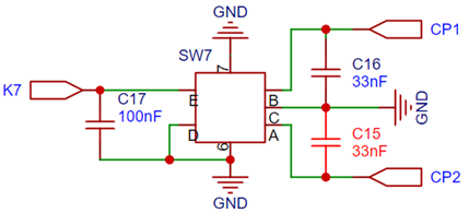
5. The pulse-encoded knob circuit
consists of one pulse-encoded knob and a filter capacitor. Note that the capacitance values of capacitors C16 and C15 need to be adjusted appropriately based on the encoder knob from different manufacturers;
otherwise, interference noise cannot be effectively filtered out during rotation. If the capacitance is too large, it will affect the signal rise time; if it is too small, it will be difficult to filter out knob jitter.
6. The LED circuit
was originally designed to use three PWMs to drive ordinary RGB LEDs. However, the effect was not satisfactory, so this part was not used.

05 Introduction to the Main Controller Bluetooth Software
——————————————————————————————————————————————————————————————
The folder in the red box below contains the main controller Bluetooth software source code and related documents.
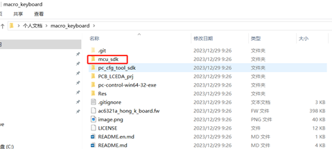
File Directory
1. Software Framework Introduction
The main control Bluetooth software is implemented in several parts, including key scanning, pulse encoder scanning, key processing, and USB HID, BLE HID, and HID report descriptors. The following is a software module block diagram. The source code involved in

the software module block diagram
mainly includes the files in the red boxes below.

Code File Structure
Key Part Software Processing Flowchart (Click the image to view a larger image)
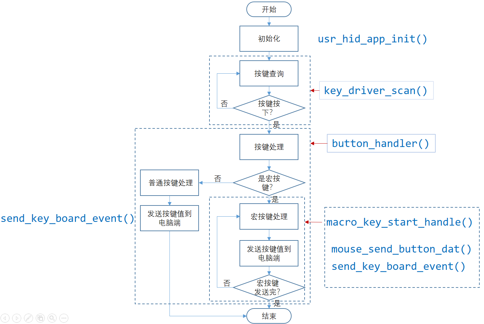
Key Processing Flowchart
2. HID Report Descriptor
USB and BLE share a report descriptor for the HID device, which is divided into 4 parts, as follows:
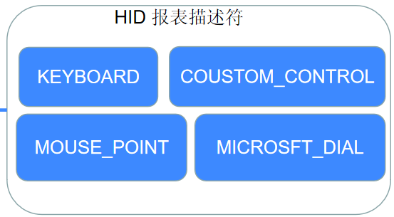
KEYBOARD: Used for reporting keyboard events.
COUSTOM_CONTROL: Used for data communication with the host computer.
MOUSE_POINT: Used for reporting mouse events.
MICROSFT_DIAL: Used for reporting Microsoft Surface-Dial control events.
The following part is the specific report descriptor, a C code array, which can be searched in the source code.
const static u8 kb_hid_report_map[];
3. Introduction to Main API Functions
int usr_hid_app_init(void); Initializes the user application.
`void key_driver_scan(void *p_dat)`: Input key scanning function, responsible for detecting key status.
`void button_handler(u8 k_id, bool pressed)`: Key handling, processes key events according to configuration information, and reports key events to the computer.
`void macro_key_start_handle(macro_k_t *p_macro_table)`: Macro key handling.
`void mouse_send_btn_handle(u8 btn_msk, bool btn_pressed)`: Reports mouse events.
`int send_key_board_event(local_k_info_t k_value, u8 pressed)`: Reports keyboard, mouse, and user-defined event information.
`static surface_dail_k_handle(u16 local_k, u8 pressed)`: Reports surface-dial knob events.
`int usr_custom_hid_rec_handle(u8 *p_dat, u8 len)`: User-defined HID report descriptor, receiving data processing functions, mainly for data interaction with the host computer. `
void hid_report_send(u8 report_id, u8 *data, u16 len)`: The main interface for sending data via the HID interface.
4. Communication data format with the host computer:
Head
Length
Pk_index
Datas
End
Checksum
0x55
1Byte
1Bytes
nBytes
1Byte
1Byte
Head: Fixed at 0x55.
Length: Equal to the total number of bytes (head + length + datas + Pk_index + checksum).
Pk_index: Current packet index.
Datas: Valid data being transmitted.
End: 1 --> Complete all data packet transmission; 0 --> Data packets still need to be transmitted.
Checksum: (head + length + datas + Pk_index) & 0xff
06 PC-side host computer software introduction
————————————————————————————————————————————————————————————————
1. Software UI Structure Introduction The
PC-side host computer software UI consists of two parts: the device page and the configuration page. The device page can be further divided into many device pages according to the product series; the configuration page consists of 6
pages , as shown in the figure below. The following pages are selected using radio buttons.

Software UI Framework Diagram
2. Software Usage Instructions
Ordinary Key Configuration

Multimedia Key Configuration

Mouse Key Configuration
Macro Key Configuration
Other Function Configuration
Surface-Dial Configuration
Open a website Configuration
The principle is to open the Run interface by pressing "Win" + "R" keys, delaying for 200ms, then entering "www.lceda.cn" and pressing Enter to enter the browser page. Note: The input method must
be in English input mode.

07 Hardware Physical Demonstration
——————————————————————————————————————————————————————————————————
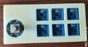
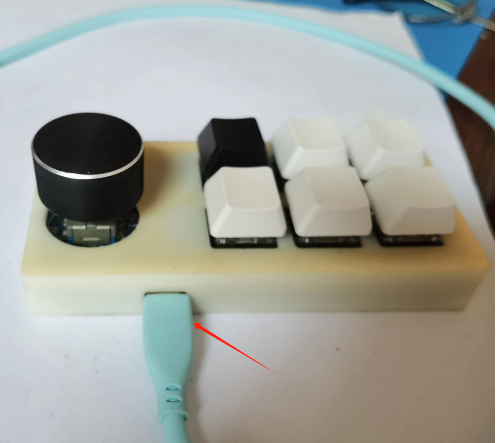
1. Below is a display of the buttons, casing, PCBA, and finished product


. 08 Other Accessories
————————————————————————————————————————————————————————————————
Accessories: BT firmware: ac6321a_hong_k_board.fw
Bluetooth AC6321A development environment and the latest official SDK, please download here: fw-AC63_BT_SDK: Firmware for Generic Bluetooth SDK (AC63 series), Support AC631N/AC635N/AC636N/AC637N/AC632N, compatible with AC69 series without audio support. (gitee.com) Accessories: PC executable file: https://cloud.189.cn/t/nyAFZ3VNVNnm (Access code: xz3x) All source code address: https://gitee.com/Bryan_He/macro_keyboard.git
09 Firmware Download
1.
Connect the USB cable to the board as follows. If the chip is blank, Jerry's forced upgrade development tool is not needed here. We only need to prepare a USB data cable as shown in the picture below. The data cable will not be needed when updating the program later (because the source code of this project has OTA function enabled). We can update the software through Jerry's OTA upgrade applet (you can search for "Jerry OTA"
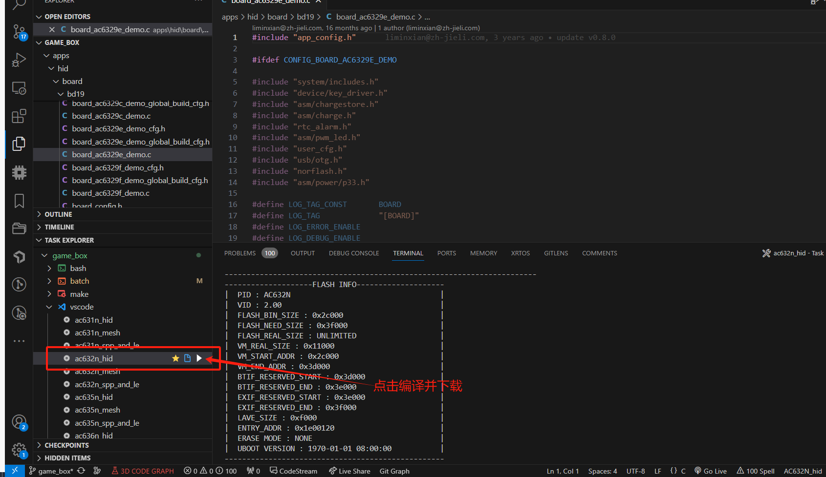
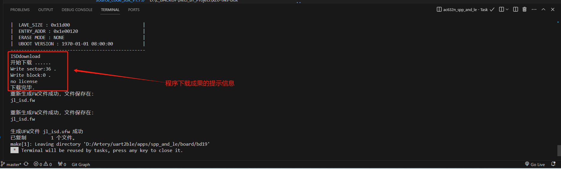
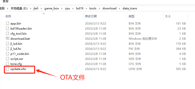
on WeChat ). Click the picture to see a larger image . After connecting the USB cable to the computer, you should be able to see the following USB device in the "Device Manager" on the computer. Click the picture to see a larger image . 2. Open the SDK source code with VS Code, and compile and download the program as shown in the picture below (if your VS Code does not have the Task Explorer plugin installed, you need to install it). Click the picture to see a larger image . You should eventually see a prompt message similar to the following, indicating that the program download is complete. Click the picture to see a larger image . 3. If OTA is required, the OTA file is in the following directory. Click the image to view a larger version . 10. Known Issues of the Project: —————————————————————————————————————————————————————————————— 1. The gap between the casing and the PCB board is insufficient. The inside of the casing needs to be manually scraped with a blade. This part needs adjustment. 2. The battery socket interferes with the casing after the battery is inserted. Adjustment is required. 3. The computer configuration tool still has many bugs . This project is my first open-source project. I will continue to turn my ideas and concepts into feasible projects, showcasing them to every enthusiast interested in embedded electronics/software. I will try my best to share my project experience, ideas, and concepts with everyone through text, images, and diagrams. Welcome to leave comments and discuss. If you think this project is good, please give it a like. Also, if you think this project has practical value, please bookmark it so more enthusiasts can see it! 11. Demo Video: ————————————————————————————————————————————————————————————————


 京公网安备 11010802033920号

 MAPLAD15KP64CTR


