Using the ESP32S3-Wroom-1 module, I implemented a Bluetooth-wired dual-mode keyboard. It supports full N-key rollover but only up to 6 keys can be pressed simultaneously (due to keyboard library limitations, which I don't know how to modify). After some research, I figured it out. The official library is well-encapsulated; you only need to modify the report descriptor.
It supports media keys, and the key bindings can be changed in the source code.
It features a partially modular design, allowing you to choose between the screen or two additional buttons, and expose unused pins for expanded functionality.
It can be battery-powered, automatically switching when plugged in, but low power consumption isn't implemented, so prolonged Bluetooth connection is not recommended. I added a deep sleep mode, but reconnection is slow—that's unavoidable.
Random thoughts: I referenced designs from various experts. Originally, I planned to use a HoloMatic C3 module + CH422 + CH9329, but after calculating the cost and considering HoloMatic's price increase and the hassle of coding, I decided to design my own development board and redesign it using the S3 module. HeZhou, you've changed!
Update:
24.11.15 Update:
I found a bug in the files from the last update. I directly modified the files in the official repository, which weren't in the project files.
The problem was with the usbmsc function. The constructor of the official USBMSC class adds an MSC interface to USB. So I deleted the content in the parameterless constructor and added a parameterized constructor to prevent adding the MSC interface when declaring the class object. This way, an inaccessible disk won't be generated when using the USB keyboard.
Solution 1: Use the latest project files;
Solution 2: Modify the corresponding files yourself as I mentioned above;
Solution 3: If you don't care about clutter when using USB mode, just delete the use_msc parameter in the error-causing USBMSC(use_msc);
I deleted the old project files, only keeping esp32s3_NKRO_keyboard.zip;
the latest project file is esp32s3_kb_v1_N8R2.rar.
24.11.11 Update:
Added USB MSC mode, when enabled, simulates the FAT partition as a USB drive for reading external configurations, etc.;
adds an Fn key toggle function, allowing switching between the original layer and the Fn layer keys;
adds screen functionality using LVGL:
displays the current connection status (Bluetooth, USB), and whether the default layer is the Fn layer or the original layer;
displays built-in images and allows rotation;
can switch between displaying external images placed on the FAT partition using MSC mode;
external images are placed in the .lvgl_data folder on the disk in MSC mode and need to be renamed to 1.png ;
adds the function of reading external configurations:
saves external configurations in JSON format, allowing configuration of key bindings, keyboard names, sleep time, etc.;
includes a key binding setting tool in Excel spreadsheet, which needs to be updated. Open the Excel file; (it needs to support VSTACK formulas, the specific version update is uncertain).
The spreadsheet is in the keyboard tools/tools folder of the latest file;
external configurations are placed in the .configs folder of the disk in MSC mode, renamed to userConfig.json;
if you need to manually write the configuration, you can refer to the defaultconfig file in the same directory;
some keyboard and encoder scanning related functions have been modified;
the latest file is esp32s3_kb_v1_N8R2.rar.
If it is an N16R8 module, you need to replace the platformio.ini file with the N16R8 version, which is already placed in the project directory, just rename and replace it.
Functionality:
Implemented features:
Wired and Bluetooth dual-mode (tested only on Windows 11);
The ESP32S3's USB port also has a serial download function. A capacitor at the boot button may cause the boot pin to power on late. If the upper left corner light doesn't flash, it may be in download mode; a power cycle will resolve this
. Switching from wired to Bluetooth does not automatically reconnect; therefore, an automatic restart is used each time the mode is switched (but note that this soft restart will increase power consumption when switching from Bluetooth to USB mode);
The keyboard supports true full-key rollover, and also supports media keys (partial support in Bluetooth mode), up to 6 key combinations at once, and 2 Fn layers;
Key values can be edited by modifying the source code;
There are a maximum of 19+1+2 keys: 19 mechanical switches in the keyboard matrix, 1 rotary encoder switch in the keyboard matrix, 2 independently controlled mechanical switches, and a screen selector.
The WS2812 features a RGB backlight, one for each mechanical axis, totaling 21 pins. Only the on/off functionality is implemented; the driver library has multiple preset lighting modes that can be modified via the source code.
It's merely a screen that lights up, sharing pins with two additional buttons. Pressing the shortcut key and then powering off and restarting switches the mode.
The code is terrible and getting worse.
A feature implemented but not verified after errors was redone:
RGB brightness is controlled via PWM on the pins. Capacitors were initially forgotten, and even with them, it might not work.
The WS2812 can control its own brightness, possibly by scaling RGB values proportionally. I'm trying PWM control; if that doesn't work, it will only be usable as a regular switch.
Expandable modules (
though this is currently unavailable): 4 touch pins + 2 ADC pins. The pins themselves have essentially the same function, but the ADC pins have reserved capacitors near the module. Using one touch pin as an ADC might affect wireless functionality.
Next to the ADC pins is a regular GPIO that can be combined to create a switch/joystick.
There are also 5 additional keyboard matrix keys, in the 5th column of the keyboard matrix.
It has one pair of serial ports and one pair of I2C pins for connecting to other chips. The I2C pins also have touch and ADC functions. There are
three startup-related pins, which are brought out for backup and can be used as GPIO after startup.
Installation Notes:
Driver Board: Powered by SY8088 DC power chip, TP4056X for battery charging, 40-pin 0.5mm pitch for FPC female connector pins;
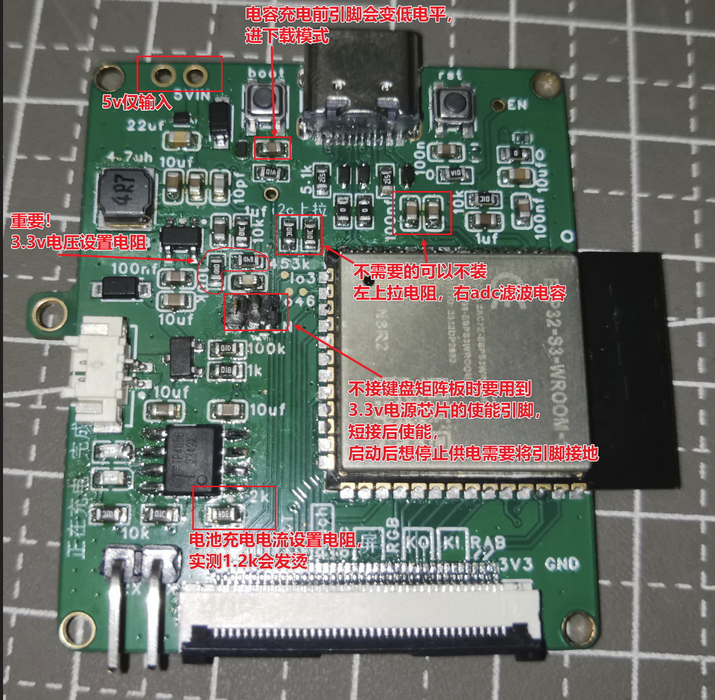
The capacitor below the boot button is optional. Installing it may require two boots to enter the normal program, as the boot level is low before the capacitor charges, which will enter download mode. 100nF is too large in practice; The
5.1kΩ resistor below the C port is related to the power supply protocol. We only need 5V power, so it's not actually necessary; (What was I writing before?) The 5.1kΩ resistor is for CTOC charging to be recognized, and it's not recommended to omit it; The
anti-static diode is too small; you can omit it if you find it difficult to install;
The values of the MOSFET and other similar pull-up/pull-down resistors, LED voltage divider resistors can be selected as needed, as long as the function is achieved;
The 5V pin on the upper left is only for input, and there is a diode connected to it (the left side is ground);
The 0Ω resistor can be replaced with wires on a different circuit board, reducing the number of resistors;
ESP32S3 module selection notes:
It is recommended to choose modules with PSRAM of 2MB or less. For modules with 8MB or more, I/O pins 33-37 cannot be used, and pins 33-34 are not brought out in any module.
For modules without PSRAM, pulling I/O45 high during power-up will cause the flash voltage to be 1.8V. It is recommended to choose modules with PSRAM to eliminate this concern.
The 499Ω resistor recommended for serial port is already connected in series in the module and does not need to be installed separately. The power supply voltage
of the SY8088 DC power chip
is determined by the two feedback resistors. It is recommended to use at least 100kΩ for the smaller one and 4.5 times that for the larger one. A small capacitor can be connected across the larger one to enhance dynamic response.
The chip enable pin needs to be connected to a 5V input and kept high to supply power. The keyboard controls the switch through this pin. However, if the keyboard matrix board is not connected, the pin shown in the diagram needs to be shorted to start the chip because of the capacitor. To stop the chip, the EN pin needs to be grounded. You can find a nearby ground to short it.
The charging current of the TP4056 is determined by the resistor shown in the diagram; if I remember correctly, the current is 1000Ω/resistance.
The keyboard matrix uses WS2812B LEDs in a 6028 package and an EC11 encoder. The PCB connects to the driver board via three 8mm double-through studs.
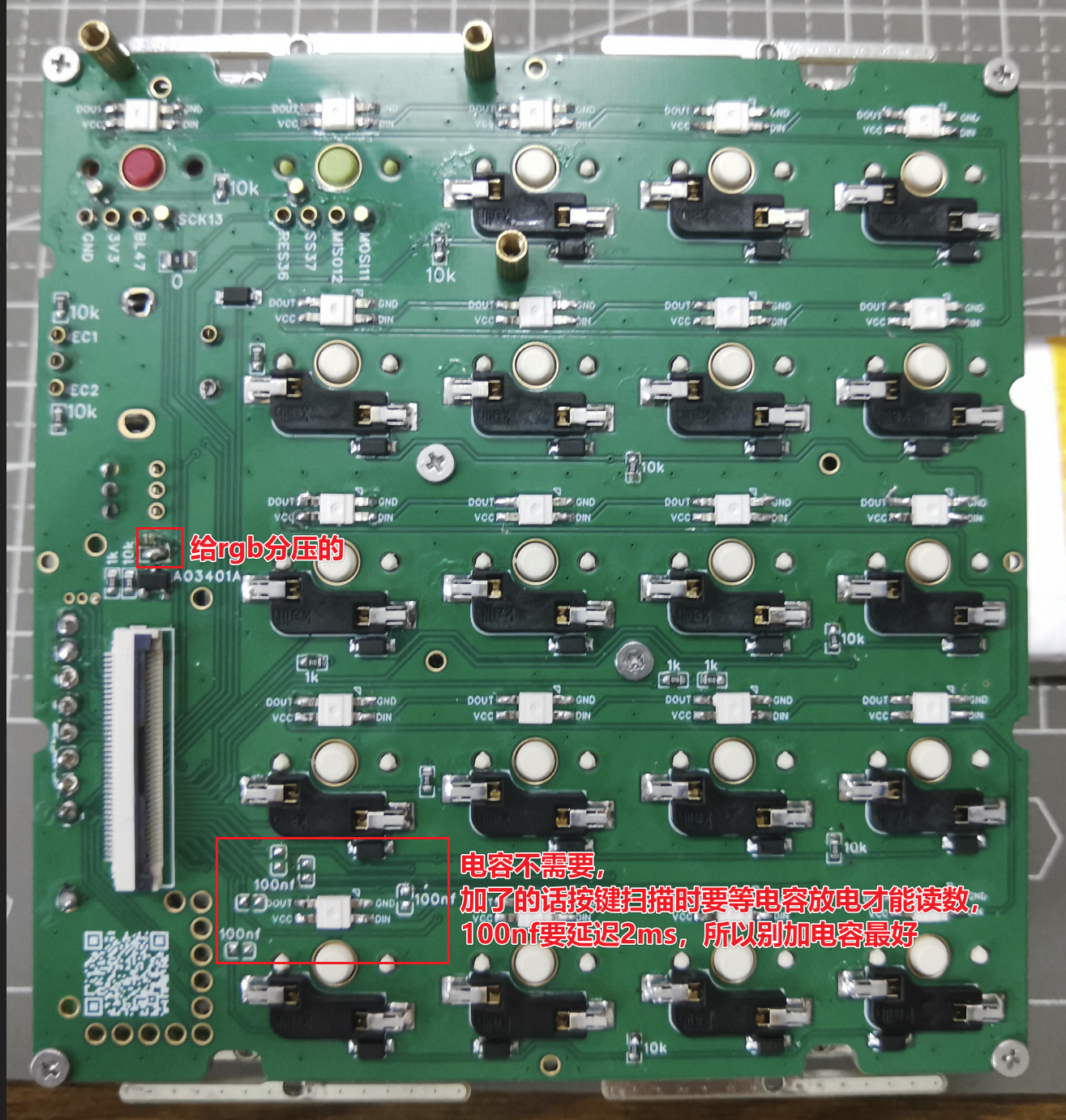
The capacitors connecting the matrix input pins are unnecessary; debouncing will be handled in software anyway, so physical debouncing is unnecessary. If you really want to add it, add a smaller one.
The 10kΩ resistor near the keys is an input pull-up resistor, and the 1kΩ resistor is an output pull-down resistor. The intention is to trigger an interrupt in sleep mode, so there's no need to set up additional pin outputs before sleep mode (although I didn't actually write any sleep mode code).
The RGB voltage divider resistors can be directly shorted. The brightness of the WS2812 can be controlled via software.
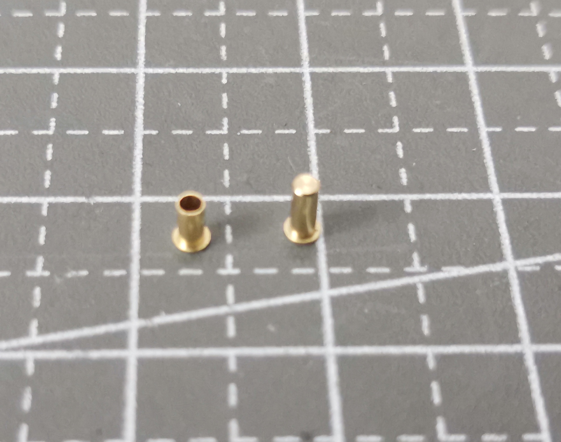
The two additional key switches use copper eyelets with claw springs; it's recommended to choose enclosed ones, as they are honestly a bit expensive. Otherwise, replacing all the switch holders with these would save a lot of space. Keyword: hot-swappable sleeve.
The encoder's five signal pins can also use this type of connector for easy disassembly, but it will wobble slightly. The ribbon cable in the diagram for
the positioning plate and battery
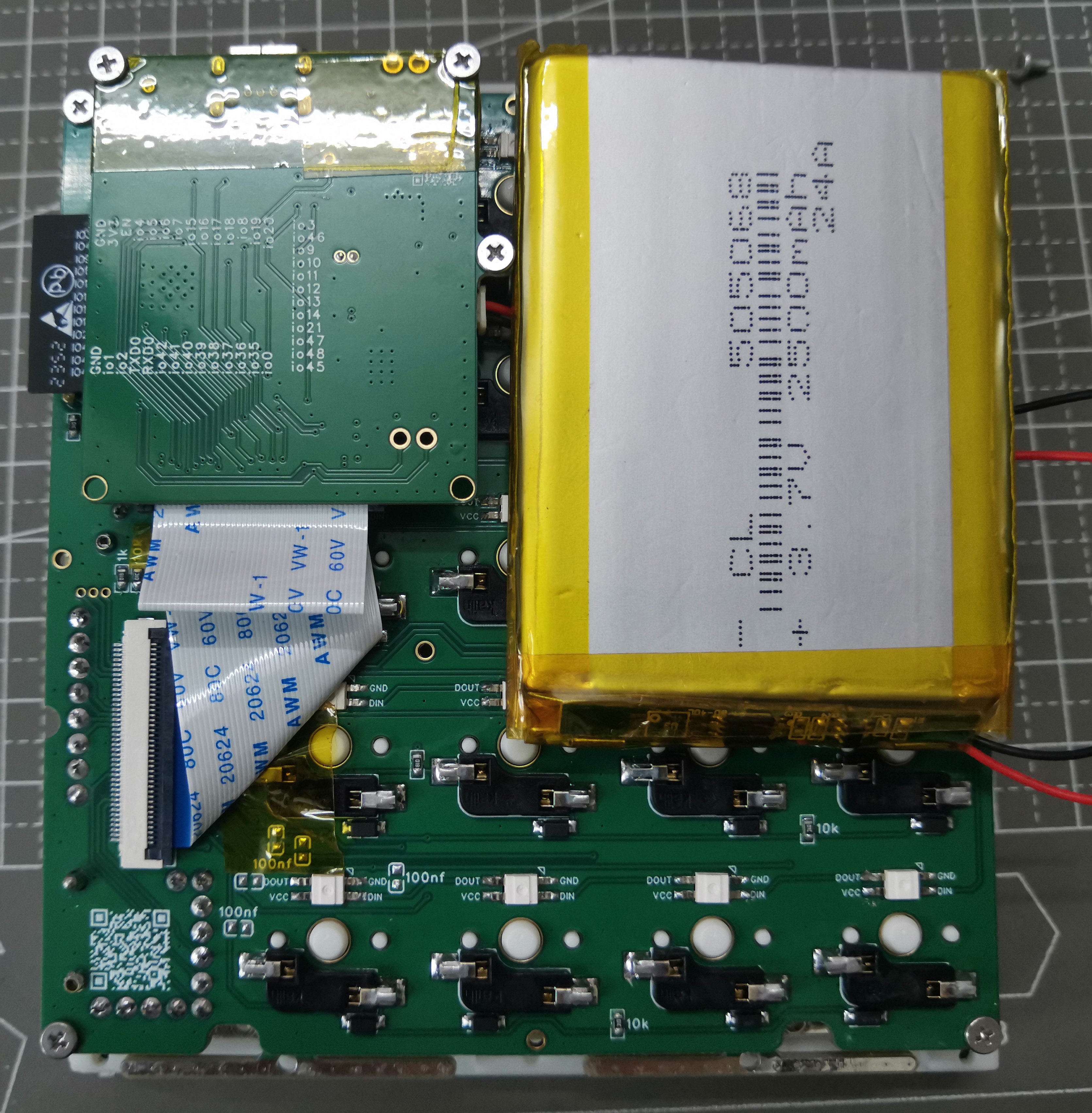
is 5mm and needs to be folded.
When the battery is placed as shown, its width is at most about 50mm; placing it horizontally at the bottom allows for greater width, but the maximum length is smaller.
The keyboard matrix and positioning plate are connected via 3.5mm studs. M2 double-through studs are available on the market, with two mounting holes at the four corners and two on the beveled side. The longest screw is 3+4mm.
There is also an M1.6 welded copper stud with a length of 3.5mm, with two welding holes at the midpoint of the four sides and two on the beveled side. The holes
in the rest of
the casing are all 1.9mm in diameter. I originally wanted to install 2.5mm knurled nuts, but after trying, the casing skipped the melting process. Since it's carbonized directly, just use M2 screws. There are clips between the cover and the bottom; if you don't mind a loose fit, you can skip the screws. For the screws between the cover and the bottom, a length of 6-8mm is recommended.
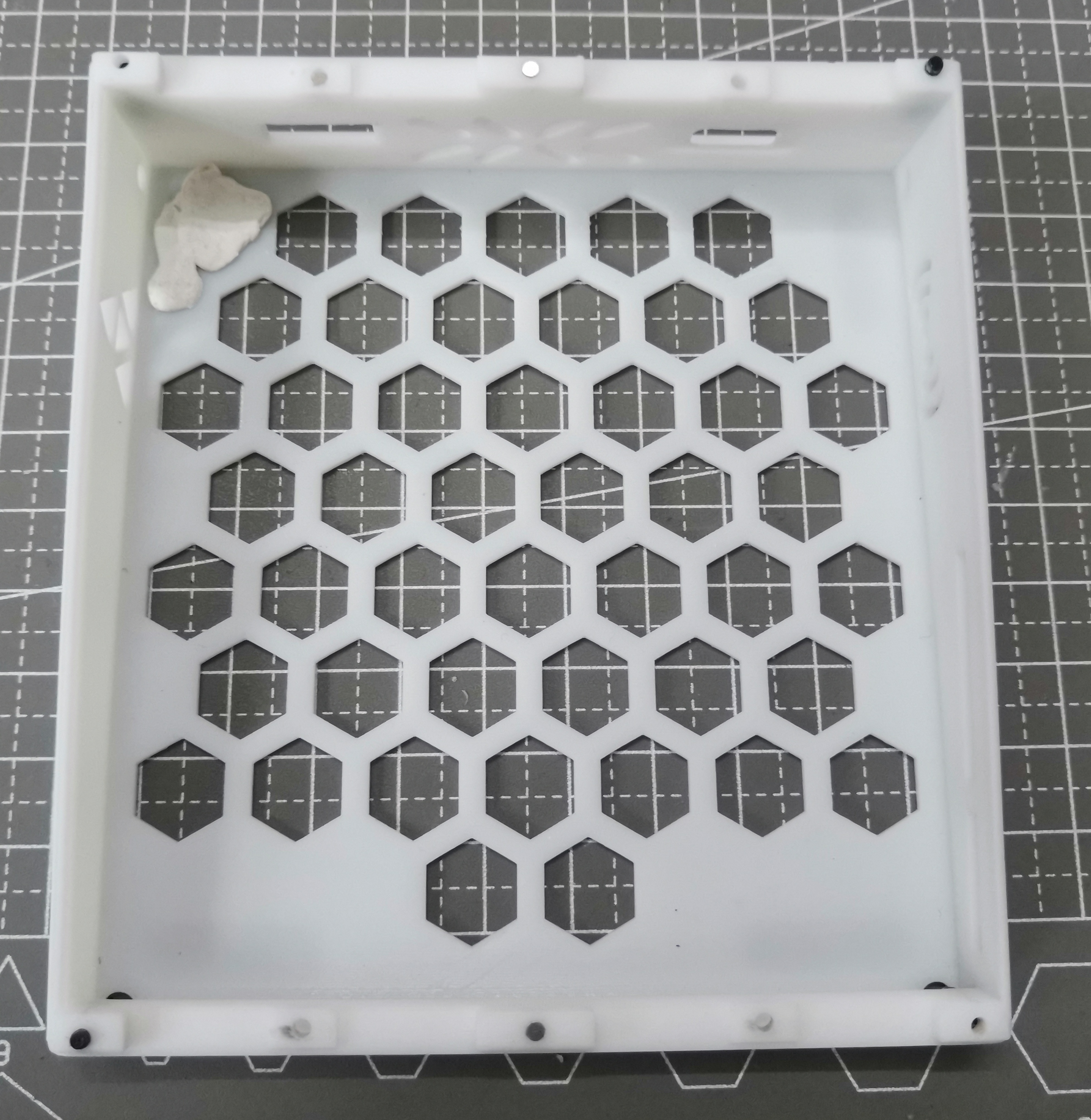
The bottom shell comes in both perforated and non-perforated versions; using 3D Monkey X resin can save you 2 yuan.
Use Blu-Tack to attach the battery for easy removal.
There are 1mm diameter, 1mm high holes in the middle of the top and bottom edges; you can install magnets, but it's difficult and not very useful.
The positioning plate is a poor imitation of the gasket structure; theoretically, you can use rubber pads to fix the four ears, but the C-port opening position needs to be calculated carefully. Use M2 screws, 4mm long.
The switch cap is A28 height, basically flush with the top of the cover.
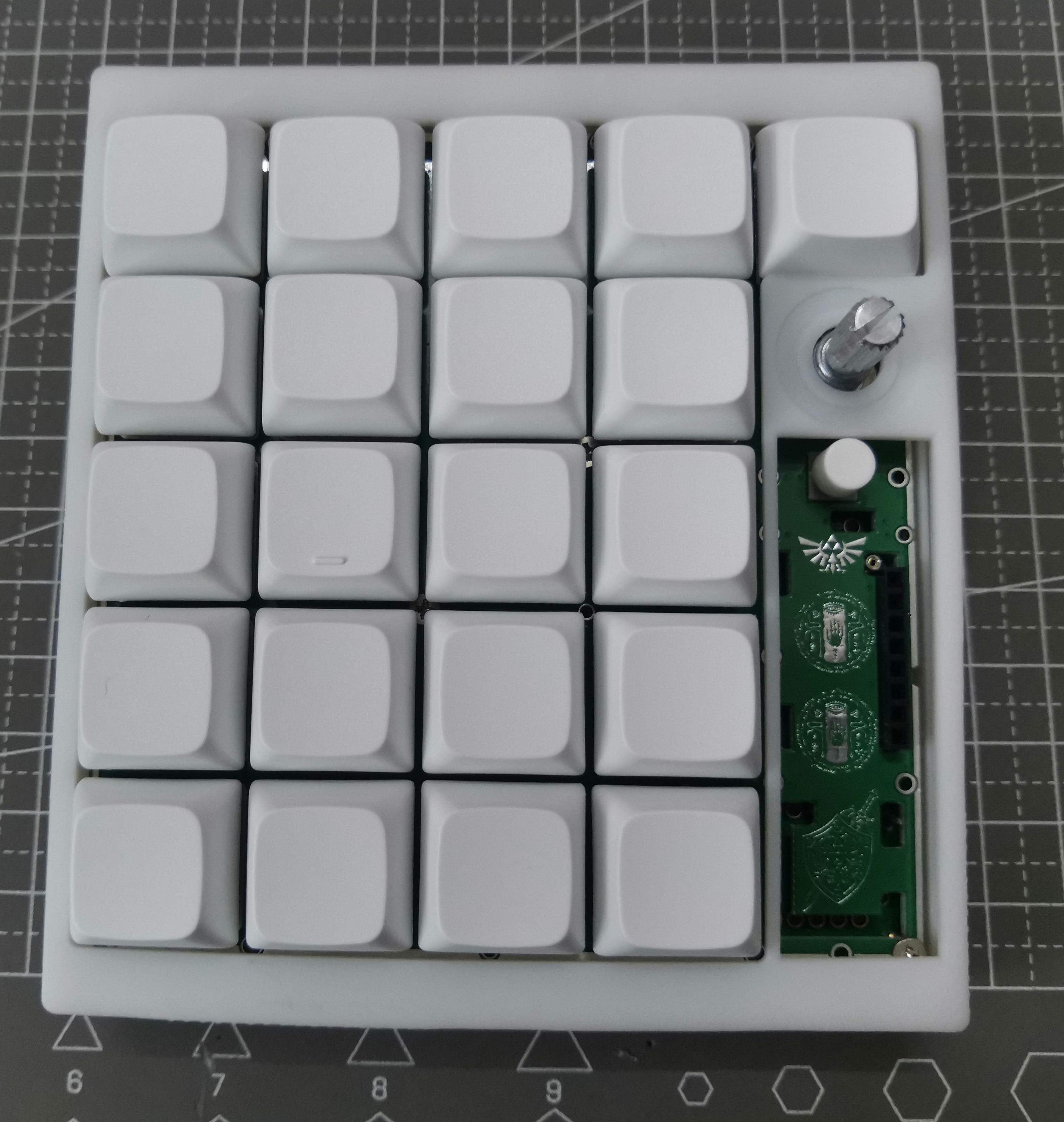

The encoder is basically centered relative to the buttons; the button spacing is 19.05mm, so an encoder cap diameter of 19mm or less is fine, but you need to consider the tolerance of the encoder shank not being straight.
The screen module

/screen shell is quite difficult to install; I suggest not installing it for personal use (since the software function isn't implemented anyway).
The screen shell is clipped to the positioning plate; you might need to remove the screen when doing so. The bottom edge of the shell needs to be pushed inwards to pull it out;
the screen module pins can be connected using 2.54mm long headers or short headers combined with header nuts;
the header length needs to be adjusted with pliers;
when using header nuts + headers, first insert the two 4-pin header nuts onto the switch housings, then insert the screen headers, which is easier to align than long headers, but requires cutting off part of the clips, as shown in the white shell in the picture above;
some
small components on the keyboard were mounted using a heat plate, while the switch housings and RGB components were hand-soldered because I was unsure of their heat resistance. I will also release the heat plate file I used, but previously a certain supplier could mount aluminum substrates with copper thickness exceeding 10cm and 1oz, but last time I saw it was only 0.5oz, so if you want to get it for free, you may have to draw it yourself;
the positioning plate was also sourced from a supplier, but for thicknesses exceeding 10cm, only 4-layer boards can be selected, and the slotting is not very precise, so it may need to be mounted twice;
after installation, I found some problems, and I slightly modified the PCB. The latest one is not exactly the same as the one in my picture, but these are minor modifications and should not affect the actual effect. The biggest problem is the positioning plate. The slot in the lower right corner of the keyboard panel was originally too short, requiring manual grinding to shorten it before installing the header nuts. This has now been corrected.
There was a definition conflict between the Bluetooth and USB keyboard libraries, so I modified some code in the libraries. If you install the libraries yourself, this conflict is normal; you just need to manually modify it. The code I provided is from Platform.io, and the entire folder is quite large, so only a portion is shown. You might need to create a new project first, import my ini file, and then overwrite my code.
I modified the HID report descriptors of the two keyboard libraries to support full-key rollover, storing 136 different keys in 17 bytes. Theoretically, this allows simultaneous pressing, but I'm too lazy to modify the key and ASCII mapping algorithms defined in the official libraries. Currently, it only supports 128 keys pressed simultaneously.
Because the implementation of full-key rollover is definitely different from a standard keyboard (boot keyboard), it's uncertain whether some very old devices will support it in boot mode.
The key configuration methods are all in the source code, so I won't go into detail here.
Because it lacks a physical battery switch like a normal keyboard, even when wired, the keyboard will still be powered by the battery after the computer is turned off. Currently, it's set to enter deep sleep after 20 minutes of inactivity in Bluetooth mode, and three times that time in USB mode.
When entering deep sleep, the USB connection to the computer disconnects (it makes a "ding" sound), and there's a delay of at least 500ms after waking up, preventing timely message transmission. I didn't bother with an instant wake-up response.
I did implement a function to read the key presses at the moment of wake-up, but the time from deep sleep to startup is at least 300ms, and then almost 1 second to USB connection to the computer, making it inappropriate to pretend a key was pressed during that time.
Because the encoder input pin is pull-up, while other inputs are pull-down, I didn't implement an encoder knob for waking up from deep sleep.
Regarding power consumption
, I measured the entire keyboard current with a multimeter without a battery connected, for reference only:
Mode
current:
Power switch off
(battery chip not connected but still enabled, DC chip not enabled):
0.3mA
deep sleep mode
: 1.3mA
chip clock frequency 40MHz (GB display is incorrect);
30mA
chip clock frequency 80MHz.
40mA
chip clock frequency 120MHz;
60mA
chip clock frequency 240MHz;
64mA
240MHz + Bluetooth
120+mA
pink light, brightness 20;
20mA
pink light, brightness 255 (max);
130mA
abnormal mode: after switching from Bluetooth to USB
(only software restart, no power switch reset);
80+mA
, it is recommended to use a clock frequency of 240MHz, don't turn the light too bright, manually restart each time you switch modes, as software restarts may not reset some peripherals;
## The latest code consists of two files: esp32s3_NKRO_keyboard and esp32s3_NKRO_keyboard_with_lib. The former runs platformio's deep clean and does not install libraries, but will automatically download them after opening; the latter includes the libraries.
I will not upload minor code changes to the attachments. You can check them on GitHub:
https://github.com/gdnre/ESP32_NKRO_KeyBoard
. Construction is complete.
If anyone wants the BOM (Bill of Materials), please leave a comment. If no one needs it, I'm too lazy to compile it; a quick check shows that the automatically generated BOM is usable.


 京公网安备 11010802033920号

 AIC1863CD


