Chip Description:
The TPS54531 is a 28V, 5A asynchronous buck converter with an integrated high-side MOSFET with low RDS(on). The device automatically activates the pulse-skipping Eco-mode function to improve efficiency under light load. In addition, the 1μA shutdown supply current makes the device suitable for battery-powered applications. Current-mode control with internal slope compensation simplifies external compensation calculations and reduces component count while allowing the use of ceramic output capacitors. Overvoltage transient protection circuitry limits voltage overshoot during startup and transients. Cycle-by-cycle current limiting, frequency foldback, and thermal shutdown features protect the device and load under overload conditions.
Module Pin Description:
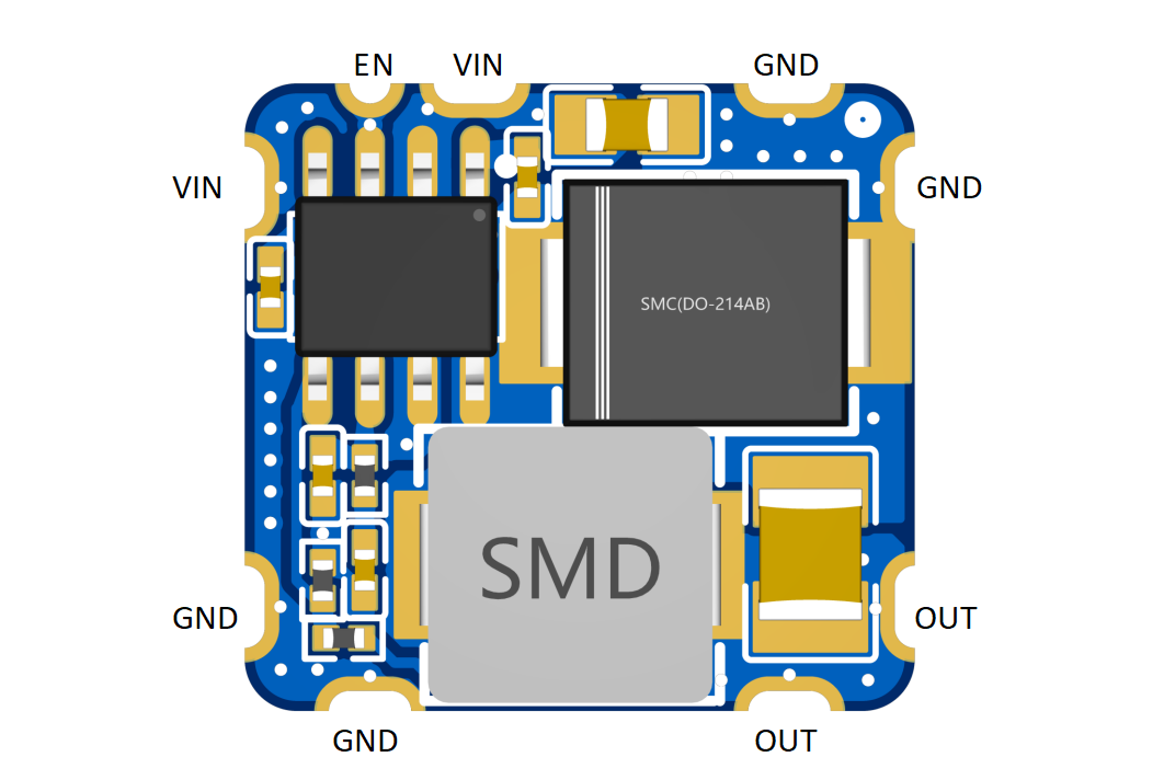
The module size is 1.5*1.6cm, and the pin spacing is compatible with perforated boards.

Output Voltage Calculation Formula:

Using the reference circuit:

Import the file “TPS54531 power module_component package model.elibz” to use the module in the project.
Precautions:
(1) The input VIN voltage must be at least 0.7V greater than the output voltage, and the stable output must be greater than 2V.
(2) With the module outputting 5V, the long-term output current is 4A. (For power consumption greater than 10W, please add a heatsink.)
(3) The stamp hole does not need to be processed using the half-hole process; you can handle it yourself.
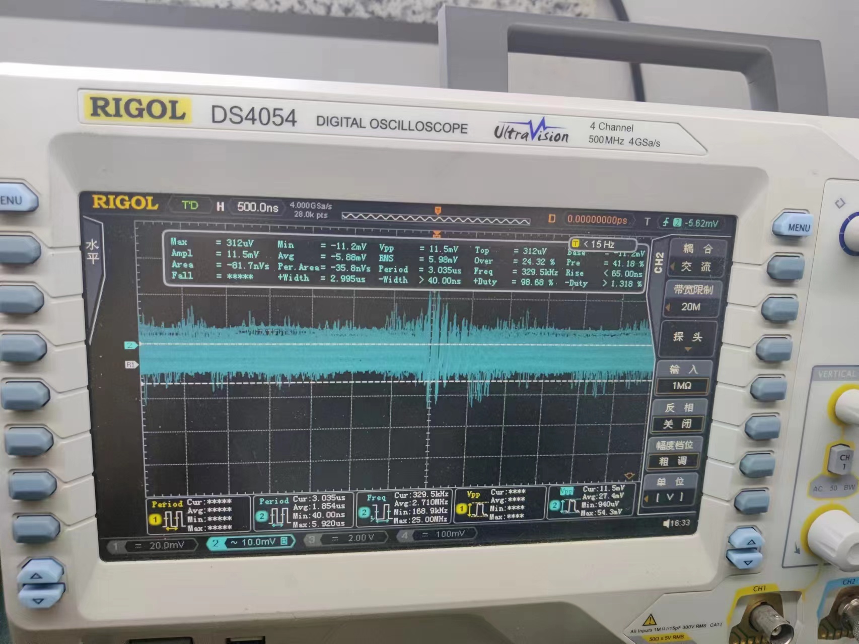
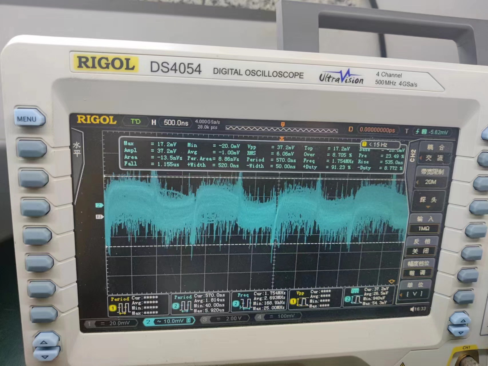
Ripple test:
Due to the lack of spring pins and limited testing conditions, the actual ripple will be lower than what is observed.
5V no load (11.5mV)
5V2A (25.6mV)

5V3A (37.2mV)
5V4A (45.9mV)

5V5A (50.0mV)

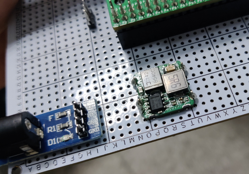
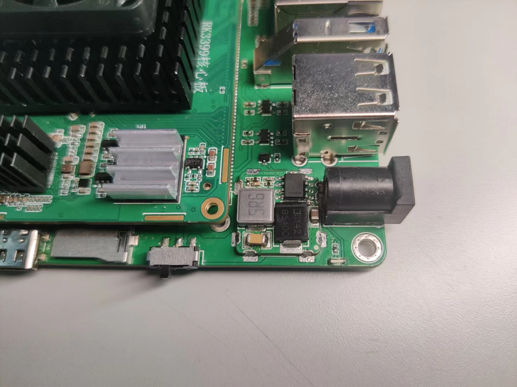
Usage demonstration:
Perforated board:
PCB:
TPS54531 Power Module_Component Package Model.elibz
Patch.mp4
PDF_TPS54531 step-down module (ultra-small size, high current).zip
Altium_TPS54531 step-down module (ultra-small size, high current).zip
PADS_TPS54531 step-down module (ultra-small size, high current).zip
BOM_TPS54531 Step-Down Module (Ultra-Small Size, High Current).xlsx
94467
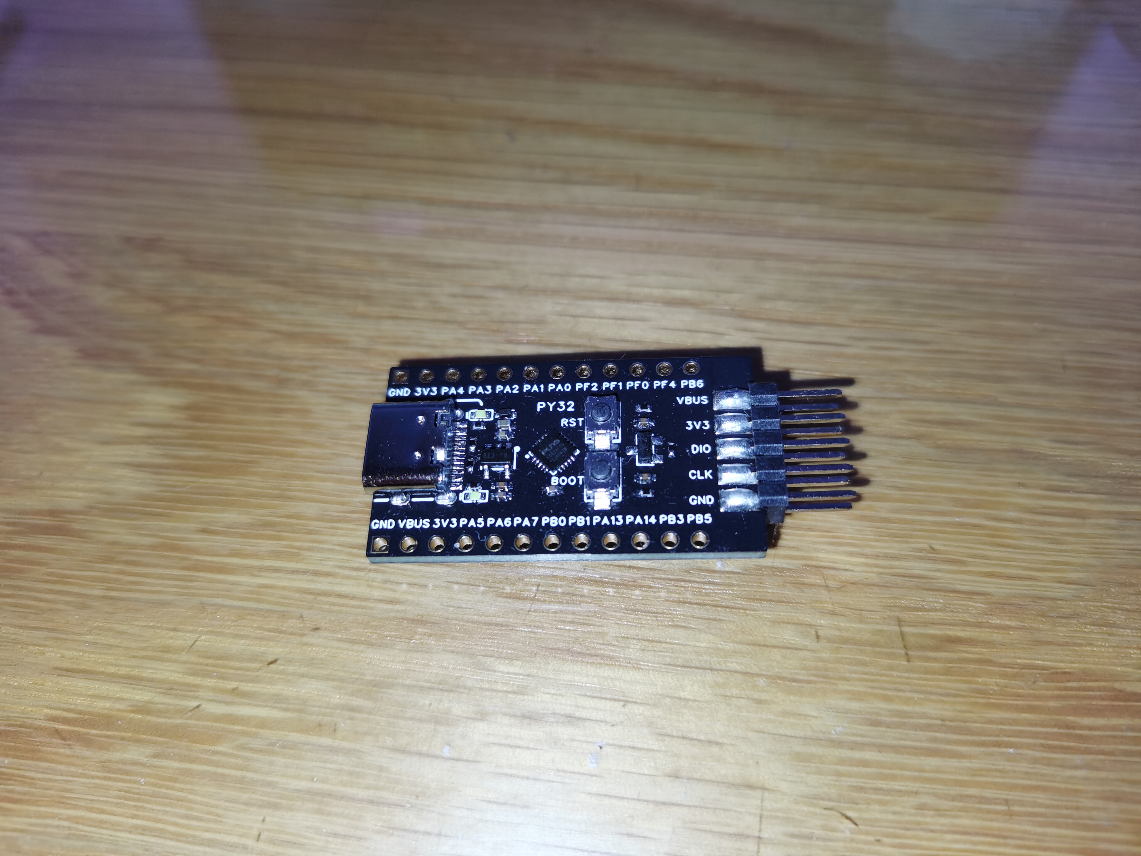
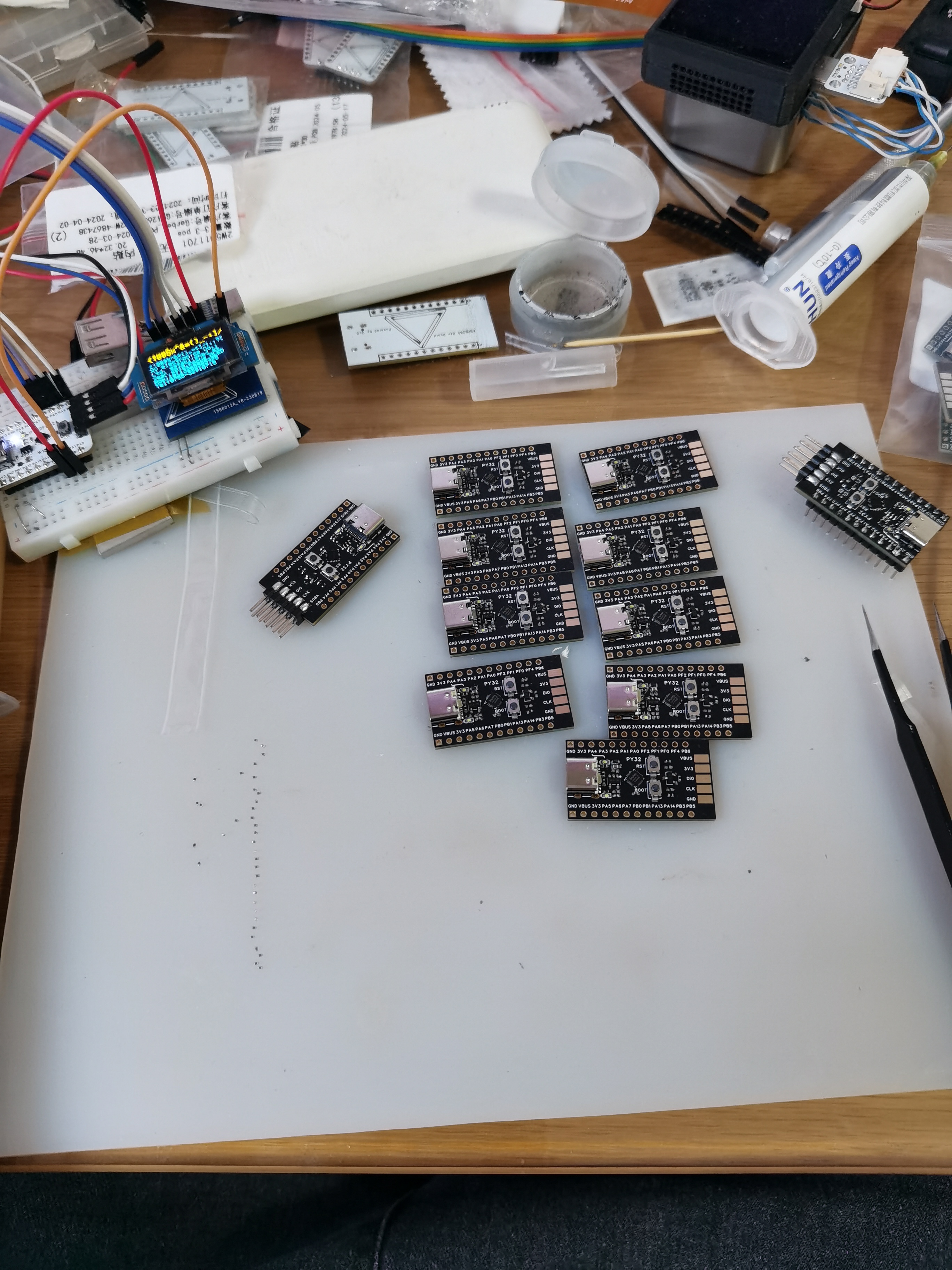
PY32F002AF15U6TR Development Board
It can be used to replace air001
Based on the PY32F002AF15U6TR microcontroller, it supports SWD debugging and Arduino automatic downloading, and can be developed directly using the HeZhou Air001 SDK.

PDF_PY32F002AF15U6TR development board.zip
Altium_PY32F002AF15U6TR development board.zip
PADS_PY32F002AF15U6TR development board.zip
BOM_PY32F002AF15U6TR Development Board.xlsx
94468
(Color silkscreen printing) Touch-controlled stepless dimming snowflake lamp
Thank you everyone for your support of the snowflake lights. I've made a color silkscreen version.
The process for making the colored silkscreened snowflake light is exactly the same as the regular version. Only display images and a PCB ordering tutorial are provided here. After ordering the PCB using the Gerber link in the bottom attachment, follow the tutorial for the regular version. Click here for
the comprehensive colored silkscreened PCB ordering tutorial for the regular version. Click here for more information. If you
have any questions, feel free to join my QQ group: Group ① - 735791683.
Some notes:
**Links to Taobao for the outer shell, snowflake light components, and finished products.**
Gerber_snow_light (slotted) 16P (cc resistor) capacitor-free version_2024-01-02.zip
PDF (Color Silkscreen) Touch-Controlled Stepless Dimming Snowflake Light.zip
Altium (Color Silkscreen) Touch-Controlled Stepless Dimming Snowflake Lamp.zip
PADS (Color Silkscreen) Touch-Controlled Stepless Dimming Snowflake Light.zip
BOM (Color Silkscreen Print) Touch-Controlled Stepless Dimming Snowflake Lamp.xlsx
94470
Fan mounting panel
Install a small 5V fan in environments where fans are needed.
The circuit has two systems: 1. A direct connection to the fan, which blows air as soon as the power is on. This is manually controlled using jumpers. 2. A temperature control system using a 555 timer to reach or exceed a set temperature (50 degrees Celsius) to activate the fan. The first version used some surface-mount components, but as shown in the soldering diagram, saving space didn't seem very meaningful, so a second adjustment was made, increasing the reserved area for the fan connector, etc., addressing the design flaws of the first version. It can now be directly PCB fabricated.
PDF_Fan Mounting Panel.zip
Altium Fan Mounting Panel.zip
PADS_Fan Mounting Panel.zip
BOM_Fan Mounting Panel.xlsx
94471
electronic


 京公网安备 11010802033920号

 MAX6440UTBGWD3+T


