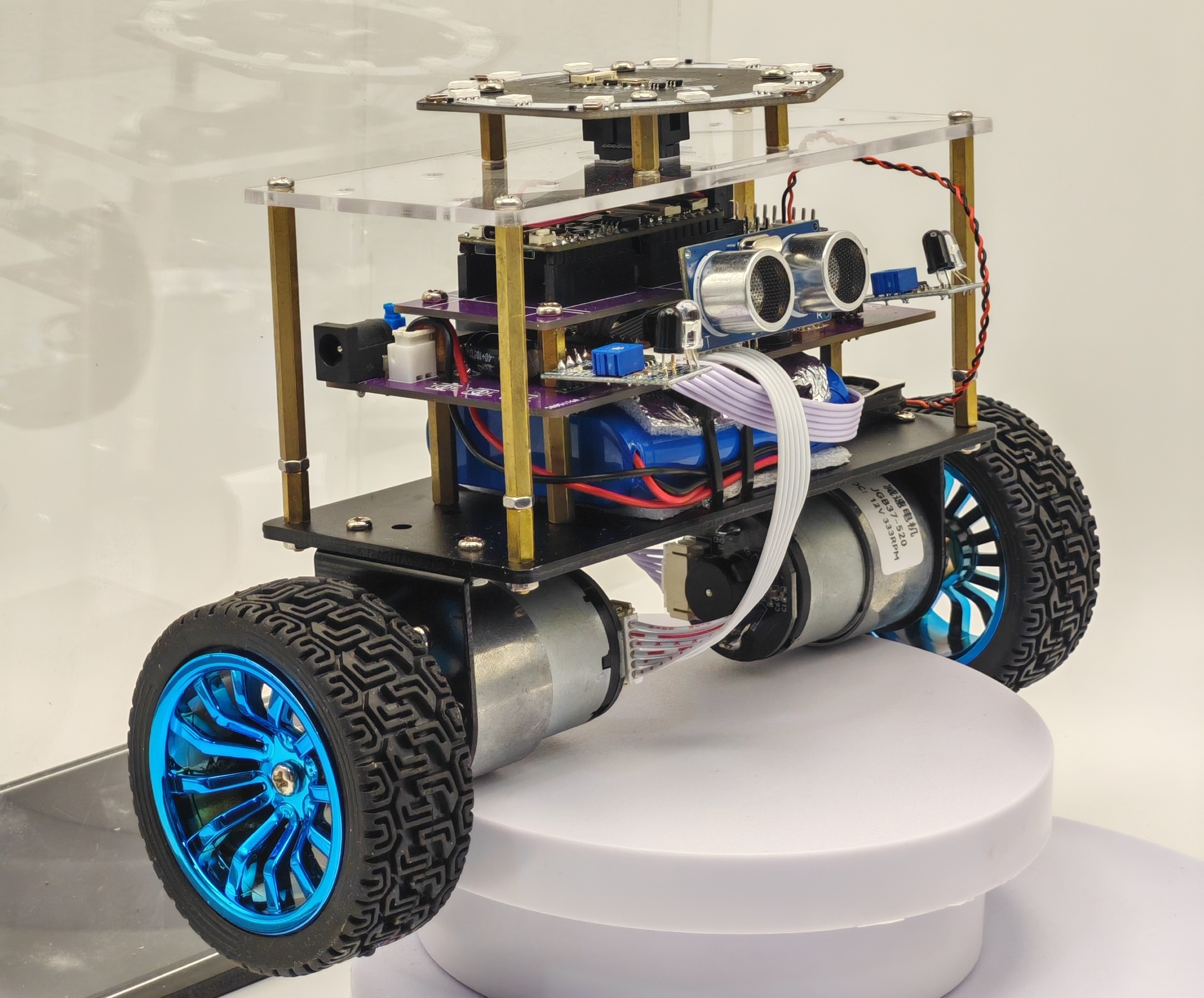
Multi-Functional Balance Scooter – An extension of the traditional balance scooter.
This scooter adds many features to the basic balance function, such as Bluetooth control, voice control, obstacle avoidance control, and follow control. Integrated together, it offers four modes: Bluetooth mode, voice mode, obstacle avoidance mode, and follow mode.
I. Origin of the Idea:
I frequently saw two-wheeled balance scooters on various video platforms and found them particularly interesting. I thought I should make my own balance scooter, but my idea couldn't be just like others', only having a balance function; I wanted to add some more interesting features. So I continued surfing the internet to see what interesting features could be added to my balance scooter. After watching many small scooter videos, I finally decided to add Bluetooth control, voice control, obstacle avoidance control, and follow control. After implementing these functions individually and then combining them, I continued to debug, frequently burning out components, replacing them, burning them out again, and finally, after continuous improvement, I succeeded. Now, I'm recording that unforgettable time.
I. Voice Control: 1. Multi-function self-balancing scooter voice mode demonstration_bilibili
II. Bluetooth Control: 2. Multi-function self-balancing scooter Bluetooth mode demonstration_bilibili
III. Obstacle Avoidance Control: 3. Multi-function self-balancing scooter obstacle avoidance mode demonstration_bilibili
IV. Follow Control: 4. Multi-function self-balancing scooter follow mode demonstration_bilibili (following the sound source)
II. Workflow
For any project, you should be familiar with how to do it, what steps are involved, and what to pay attention to. Only after clarifying these steps can you reasonably allocate your energy to perfect each step.
My workflow for this project is specifically divided into six steps:
I. Module Porting
1. CW32F030 MCU Application: Proficient use of CW32F030C8T6 peripherals such as GPIO, USART, IIC, TIM (used most frequently later), and all its function APIs is the foundation for all subsequent steps; you can learn from the official "CW32 Ecosystem Community" account on Bilibili.
2. OLED Screen Driver: This screen driver chip is an SSD1306 with a 128*64-bit memory size. A 0.96-inch OLED has 128*64 pixels, meaning each bit corresponds to one pixel. To display data on the OLED, a command function is used to set the corresponding registers, and then a data transmission function is used to manipulate the memory.
3. MPU6050 Gyroscope Driver: This sensor requires IIC data reading functions. Similar to the OLED, a command function is used to set the corresponding registers to enable the gyroscope. Then, the data reading function is called to read the gyroscope's raw data (including three-axis acceleration and angular velocity). To use it on a balance scooter, this raw data needs to be used for attitude calculation to obtain the three-axis angles relative to the ground. Data processing methods include "first-order complementary filtering + Kalman filtering," and "directly obtaining the ground angles from the DMP module inside the driver MPU." This is the data we ultimately need.
4. Ultrasonic Module Driver: The HC-SR04 module is a very common ultrasonic ranging module. It uses GPIO peripherals and interrupts. A high-level signal is given to the IO pin to transmit ultrasonic waves and simultaneously enable interrupts and timers. After receiving the signal, the interrupt is entered to retrieve the count. Combined with the speed of sound (approximately 340 m/s), the distance can be calculated and written into the software logic.
5. Buzzer Module Driver: Each buzzer driver consists of an amplified signal of a certain frequency output to the positive terminal of the buzzer. The duty cycle of the signal determines the loudness of the sound. A common buzzer frequency is 2700 Hz. Only a timer peripheral is needed; the prescaler coefficient and reload value need to be set. The loudness is controlled by enabling/disabling or adjusting the duty cycle, which is embedded in the software logic.
6. Infrared Sensor Usage: Infrared sensors only have two values, 1 and 0. The IO port is initialized, and the value is read as needed.
II. Functional Module Learning
1. Voice Module Selection and Programming Method: The voice module used is ASRPRO, with 4MB of storage and up to 300 custom words; the programming environment is Tianwen Block, which supports graphical programming; detailed explanation follows.
2. Bluetooth Module Usage and Adaptation Software: The Bluetooth module used is BT04-E, supporting BLE and SPP; it offers stable transmission, long range, and official adaptation software, especially the smart car component.
3. Logic Embedding the Obstacle Avoidance Module in the Program: The driver has already been implemented; this section focuses on refining the ranging logic and its coordination with infrared.
4. Microphone Array Driver and Usage: A 6+1 microphone array is used, with the communication protocol being IIS (audio-specific). The driver's main controller is Maix bit, using the MicroPython function library; detailed explanation follows.
III. Hardware Design
1. Drawing the peripheral circuits of functional modules: After implementing all the above functions, you should have a clear understanding of what type of pins each function requires and what function each pin needs to be multiplexed for. Therefore, after drawing the minimum system, naturally, after drawing the basic circuits of each module, connect their common pins together using jumpers, or directly use the same name. This ensures that the network identifiers are the same and they are connected together on the PCB.
2. Note: When drawing the peripheral circuits of the modules, ensure that the communication level is consistently 3.3V. Some modules can be powered by either 5V or 3.3V, and if the module's built-in circuit lacks a 5V to 3.3V converter, it may burn out the MCU. Therefore, always use 3.3V power.
IV. Program Integration and Debugging
1. Unified framework: Establish a framework by writing the above functional modules in parallel, specifying which module enables and disables each function.
V. Improve the Mechanical Structure
1. Refine the project: Disassemble and optimize the structure to ensure the axles of both wheels are aligned, minimize the height to lower the center of gravity, customize an acrylic shell, and neatly organize exposed wires for a more aesthetically pleasing appearance.
VI. Adjust Parameters and PID
1. Adjust the PID: After determining the center of gravity by improving the mechanical structure in the previous step, adjust the PID parameters to achieve the ideal balance of the self-balancing scooter.
2. Adjust parameters such as speed: Adjust the forward speed, backward speed, turning angle, etc. of the self-balancing scooter in various modes.
III. Specific Steps and Contents
I. Module Porting
1. Application of CW32F030 MCU: There's not much to say about this step, as it involves uncontrollable factors such as personal perseverance and the length of learning time. You need to learn it yourself, but in fact, this project doesn't use many peripherals. Being proficient in using GPIO, EXTI, USART, and SPI is enough (IIC is analog). If you don't have a foundation, it's best to focus on learning.
2. OLED Screen Driver:
As mentioned earlier, to make this screen display the data we want, we need to send commands to it via the IIC protocol to set the registers, and then operate on the OLED's display memory by sending data, which means lighting up the corresponding pixels.
Below is a detailed explanation of how to display a '1' from 0:
We are using simulated IIC, meaning we use GPIO to simulate the high and low levels in IIC by setting 1 and 0, and change the IIC speed by changing the delay time for setting 1 and 0.
As shown in Figure 1:
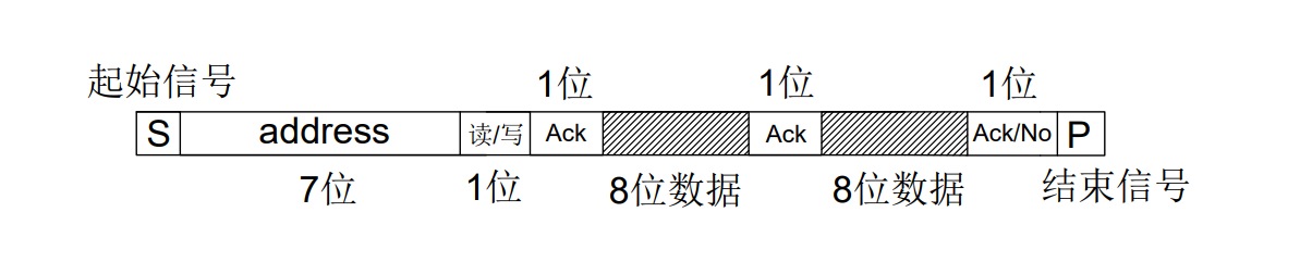
Figure 1 describes the basic structure of IIC communication, including a start bit, 8 bits of data, an acknowledge bit, and a stop bit. This structure is also the structure that IIC needs to follow when sending 8 bits of data, which is a characteristic of IIC. We need to use our GPIO to simulate this IIC structure, namely the start bit, 8 bits of data, acknowledge bit, and stop bit, by setting 1 and 0 and using delays.
Figure 2:

As shown in Figure 2, to simulate the IIC structure using our GPIO through setting 1s and 0s and delays, we need to understand the specific structure of the start bit, 8-bit data, acknowledge bit, and stop bit. As you can see from left to right in the above protocol frame: START is the start bit. To simulate this sequence using GPIO, simply set the simulated SDA and SCL to 1, then set SDA to 0, leave SCL alone for now, delay (or leave it alone), and then set SCL to 0. Then, encapsulate this into a function, and you're done.

The stop bit works similarly; simply set the simulated SDA and SCL to 0, then set SCL to 1, leave SDA alone for now, delay (or leave it alone), and then set SDA to 1.

The acknowledge signal ... The simplest approach is to indicate whether data has been read since it doesn't involve reading data.

Writing a single byte is slightly more complex, requiring eight iterations of SCL and SDA, each representing one bit of data, meaning outputting eight bits and sending one byte of data.
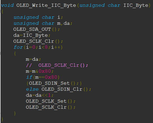
Encapsulating these functions one by one simulates the start bit, 8 bits of data, the acknowledge bit, and the end bit. Calling these functions sequentially creates the complete IIC protocol. Note that `OLED_SDA_OUT()` configures the I/O port as a push-pull output. In the current environment, this configuration only needs to be done once, as the I/O port only needs to be configured as an input when data is read.
Figure 3:

As shown in Figure 3, after simulating the start bit, 8-bit data, acknowledge bit, and end bit, calling these functions in sequence constitutes the complete IIC protocol. The above are two examples. The start bit, 8-bit data, acknowledge bit, and end bit are arranged in order. The data 0X78, 0X00, and 0X40 sent represent the OLED address, the command to be written, and the data to be written, respectively. These data are no longer within the scope of the IIC protocol; different devices that conform to the IIC protocol will have different values. By writing the command using the function above and the data using the function below, the OLED can normally receive the data we send.
Figure 4:

As shown in Figure 4, we mentioned above that after setting some corresponding registers using the send command function, we can then use the send data function to operate on the display memory. After simulating the start bit, 8-bit data, acknowledge bit, and end bit using GPIO, we also encapsulated the send command function and send data function. Now, we use the send command function to set some registers in the OLED. You'll have to translate the specific settings yourself; you can find Chinese comments online. It's roughly about setting things like ranges, whether to display in reverse, etc. After this step, we arrive at the final step of sending data to display the '1' we want.
Figure 5:

As shown in Figure 5, this function associates the character we want to display with the character we fill in the brackets. Because if we fill in the character '1', the OLED won't recognize it. We need to provide the OLED with a character library. F8X16[c*16+i] describes an 8*16 pixel character library, which describes how 0-9 should be displayed. The data in the character library corresponds one-to-one with the data we want to display. The character library is the language of the OLED, and '1' belongs to our human language.
Figure 6:
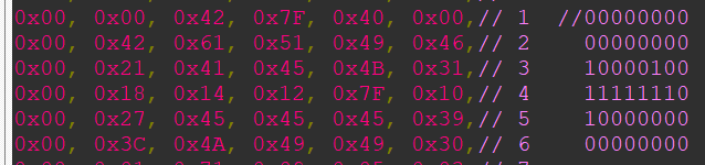
Like this 0x00, 0x00, 0x42, 0x7F, 0x40, 0x00, this is the '1' that the OLED recognizes. We send these 6 data to the OLED, and the OLED will display '1' on the screen. In the middle, there is a modulus process. If you look closely, you can see that if you write the data expressed by these 6 bytes in order into binary, and connect all the '1's in the binary, you can see that the data expressed inside is the '1' that we humans recognize as falling to the right.
This concludes how to go from 0 to displaying a '1'.
3. MPU6050 Gyroscope Driver:
The IIC driver of the gyroscope is similar to that of the OLED. The start bit, 8-bit data, acknowledge bit, and end bit are shared. The difference is that (1) there is an additional function to read data, (2) it needs to wait for an acknowledge signal, (3) it needs to send an acknowledge or no acknowledge signal, (4) and the gyroscope address mentioned above, the difference between writing commands and writing data.
Figure 7:
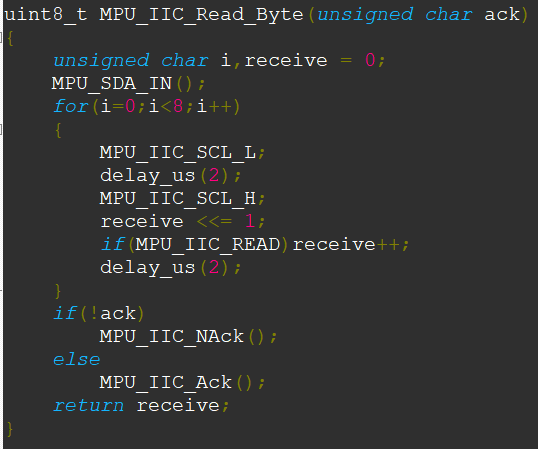
As shown in Figure 7, this function describes how to read 8 bits of data from the SDA pin. Similar to sending 8 bits of data in IIC, it requires 8 loops. The difference is that (1) MPU_SDA_IN() needs to be called in advance, that is, the SDA pin needs to be set as input; (2) an 8-bit local variable needs to be defined. Each bit of data is read and shifted one bit to the left to store it. After 8 loops, a whole byte is stored; (3) after receiving a byte, regardless of whether the correct data has been received, a signal for acknowledgment must be sent.
Figures 8.1, 8.2, and 8.3

: The first figure describes the need to wait for the other party to acknowledge, because in this communication mode, it is necessary to repeatedly confirm whether the other party is online and whether the data sent has been correctly received; the second and third figures describe sending an acknowledgment signal or a no-acknowledgment signal. If you acknowledge, the other device will consider you to be normal and will continue to send data. If you do not acknowledge, the communication will end directly.
Up to this point, it all belongs to the IIC protocol layer. The next part is unique to the device.
Figure 9:

These two functions in Figure 9 incorporate the features of the MPU6050. From this, we can see the difference between the MPU and OLED using IIC. OLED sends 8 bits of data, 0X78, 0X00, and 0X40, representing the OLED address, an upcoming command, and an upcoming data write, respectively. The MPU uses ((MPU_ADDR).
Figure 10:

As shown in Figure 10, this function is the most crucial step in using IIC, setting the corresponding registers. Chinese comments are best provided; they will help you understand how each register is set. After calling this function:
Figure 11:
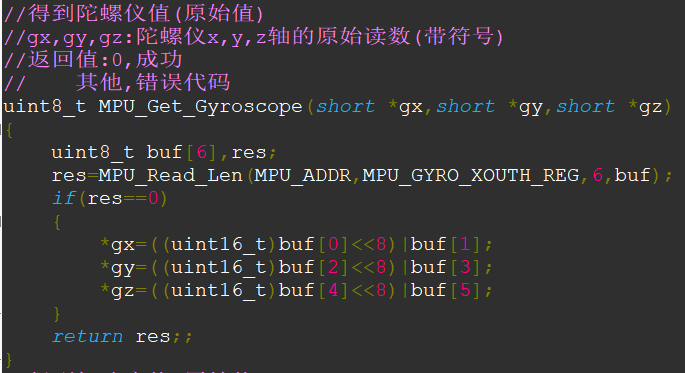
As shown in Figure 11, calling these two functions and passing in 6 pointers will obtain the angular velocity and acceleration of the three axes. These are saved as raw values and can be further processed to obtain the three-axis ground angles (using first-order complementary filtering + Kalman filtering); or, as I will introduce below (using the internal DMP library):
1. First, obtain the DMP library. This library is quite common, and you can also copy it from my project:
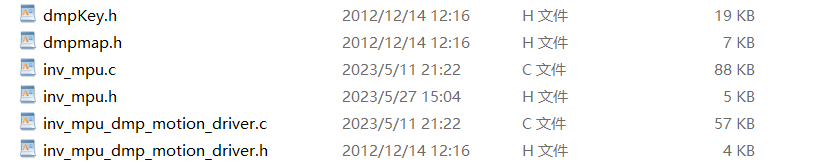
Add the two source files from the library to your project, and then specify the header file path to this folder;
2. Open the two source files respectively to see some millisecond delays. You may need to replace this part with your defined millisecond delay function, as this is required by the DMP library;
3. After defining all the functions for reading and writing one byte, you also need to implement two functions:
uint8_t MPU_Write_Len(uint8_t addr,uint8_t reg,uint8_t len,uint8_t *buf);
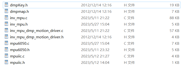
uint8_t MPU_Read_Len(uint8_t addr,uint8_t reg,uint8_t len,uint8_t *buf); These two functions are for continuous writing and continuous reading, and are required by the DMP library. It is best to port all the following files over, otherwise it is very easy to make mistakes:
Finally, after all the functions are defined, call uint8_t The function `mpu_dmp_get_data(float *pitch,float *roll,float *yaw)` can directly obtain the angles of the three axes relative to the ground, which can then be used directly.
4. Ultrasonic Module Driver: The following modules are relatively simple, using GPIO and TIM:
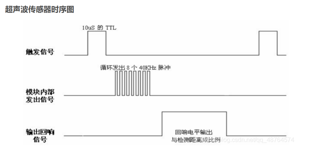
The timing diagram above shows how the ultrasonic module is used:
1. Initialize the transmit and receive pins, initialize the timer, and set the transmit pin to 0 during initialization;
2. Set the transmit pin to 1, delay for 15us, then set it to 0, triggering the module to continuously emit ultrasonic pulses;
3. Enable the receive interrupt, triggered by rising and falling edges. When the interrupt is triggered, a high level is detected, and the timer starts counting;
4. When the interrupt is triggered again, a low level is detected, the timer is disabled, the count is retained, and the count value is cleared;
5. Calculate the time for each movement based on the set reload value and prescaler value, multiplying this by the count value to get the time for the sound to travel between the module and the obstacle. Calculate the distance using the speed of sound (340m/s).
5. Buzzer Module Driver:
The common buzzer frequency is 2700Hz. For different frequencies, consult the seller or datasheet.
1. Initialize TIM so that the main frequency / (prescaler * auto-reload value) is approximately equal to 2700.
2. Set the buzzer duty cycle to enable the timer. Changing the duty cycle will change the loudness.
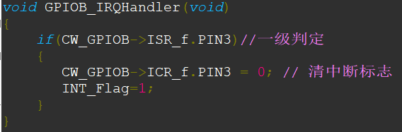
6. Infrared Sensor Usage:
Initialize the I/O port and enable falling edge interrupts. Handle the interrupt within the interrupt handler.
II. Functional Module Learning
1. Voice Module Selection and Programming Method:
For selection, a common programmable voice module, ASRPRO, was chosen. It is a 32-bit MCU with a RISC core architecture. The peripheral circuit only needs to add a microphone and a speaker.
(1) Compilation environment: Just search for Tianwen Block to download.

(2) Select the motherboard and check the serial port connection: Download the program through ASRPRO's serial port 0. PB5 is TX and PB6 is RX. (

3) Interface description:
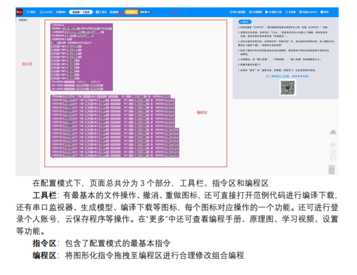
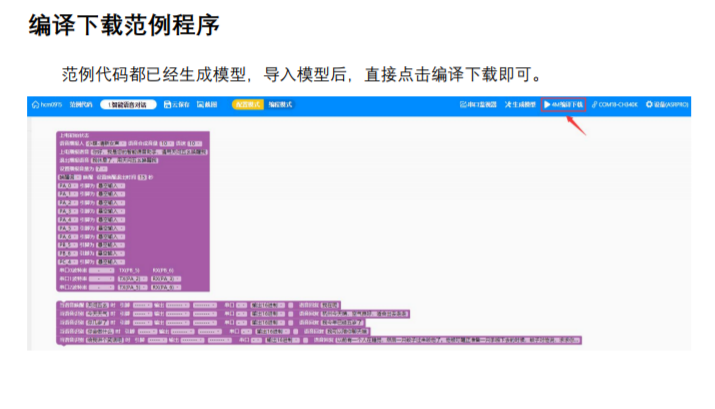
(4) Open the example program and set the compilation and download mode:

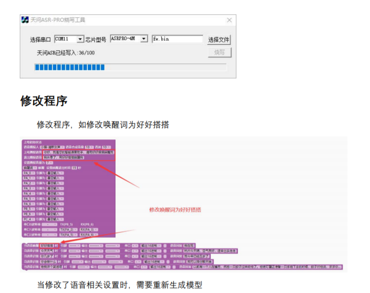
(5) Compile and download the example program. After successful download, modify it as needed and then regenerate the model for download.
2. Bluetooth Module Usage and Adaptation Software:
The Bluetooth module used is BT04-E, supporting BLE and SPP; it offers stable transmission, long range, and official adaptation software is available. Serial communication is sufficient.
The smart car component can be used directly:

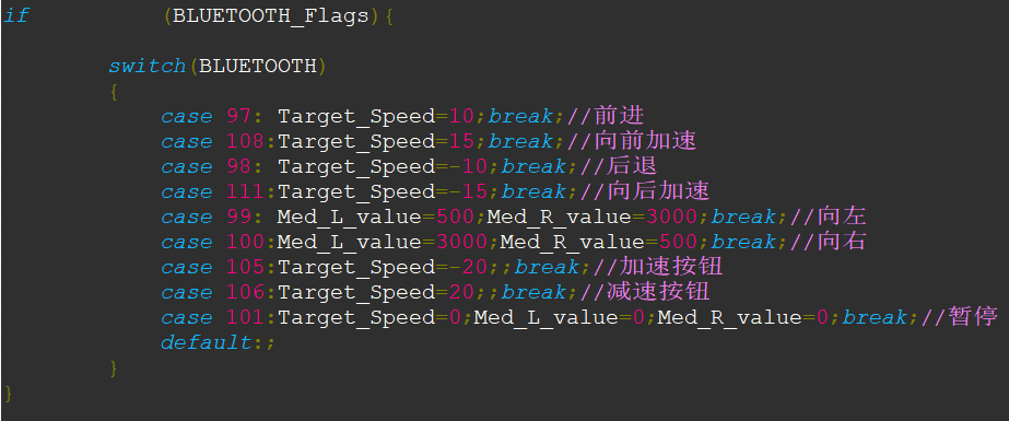
simply connect it to the Bluetooth serial port using a USB-to-TTL adapter. The default Bluetooth serial port baud rate is 9600. By clicking the buttons mentioned above and printing the values on the computer, you can see what each button corresponds to. Using these values, along with switch statements, clicking different buttons executes different forward and backward commands for the car, making it easy to use.
3. Embedding the Obstacle Avoidance Module Logic in the Program:
This logic is only reflected in the program and can be added later.
4. Microphone array driver and usage:
The function required in this project is to detect the location of the sound source. The driver is a Maix bit, which is an AIOT development board designed based on the edge intelligent computing chip K210 (RISC-V architecture 64-bit dual core) of Canaan Creative Technology.
With a 6+1 microphone array, the sound source size in 6 directions can be detected. The specific steps are as follows:
1. Configure the development environment:
(1). Install USB driver - Sipeed Wiki
(2). Install and use MaixPy IDE - Sipeed Wiki
2. Slightly modify the sound source localization routine and limit the data to be emitted to a minimum value:

3. Use the download software uPyLoader to replace main.py in the firmware with the main.py we wrote (renamed from sound source localization), so that the modified program can be executed directly when the machine is turned on.

III. Hardware Design
There's not much to say about the hardware design, as it doesn't involve much analog or digital electronics knowledge. Here are a few key points:

The diagram is somewhat haphazard, but its purpose is to clearly show the power consumption distribution, the modules involved, and how each module can be powered off using PMOS and NMOS structures when not in use to achieve zero power consumption.
1. The 12V to 5V converter schematic should follow the datasheet. It's a standard 12V to 5V converter, but the datasheet describes the inductor size as 33uH for 0-15V and 47uH for 0-30V, so the inductor was changed to 47uH.
2. The USB to serial port is mainly for debugging the voice module, Bluetooth module, and sound source localization. There are 6 switches to select these 3 pairs of functions.
3. The voice + sound source localization adapter under the MPU6050 circuit is connected to the expansion board via a 6-pin XH2.54 interface.
4. Then there's the Bluetooth module circuit. The WS2812, obstacle avoidance, and warning circuits all share a common PMOS+NMOS structure. PMOS is typically used for upper-side control. The initial idea was to achieve zero power consumption in other modes by directly cutting off the MOSFETs when one mode is running. Each MOSFET has a small switch connected in parallel for debugging purposes.
Each I/O pin of the CW32 has an internal protection circuit, clamped by two diodes pointing in the same direction, ensuring the external voltage doesn't exceed approximately 3.7V or fall below approximately -0.3V.
Therefore, this structure was used to control the 5V input to the circuit. Each circuit uses a separate 5V to 3.3V converter to ensure the 3.3V inputs of each circuit don't interfere with each other.
IV. Program Integration
1. Establish a strategy: organize all functions into a large loop. Since we previously configured the MPU6050 registers to trigger an interrupt every 10ms, we can use this to make the entire large loop execute once every 10ms. To achieve this, we only need to:
A trigger flag is set up, and the program is executed by checking the flag in the main loop. Since the flag is set every 10ms, and the main loop executes once every 10ms, the main loop will be executed once every 10ms.
In the corresponding main function:

2. First, the three serial port receiving functions determine the current mode of the vehicle. Since the receiving flag is used to determine if there is new data, the flag will not be arbitrarily refreshed.
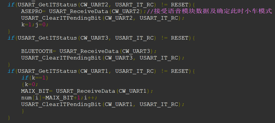
3. The current mode is determined by the data received from the voice module, and it will not be changed until another mode is available.

4. Bluetooth Mode:
5. Follow Mode: First, collect 5 received sound source data points, sort and filter them to confirm the true direction of the sound source. Then, based on the different deviations of the sound source from the direction of travel, apply different forward force to the left and right wheels.

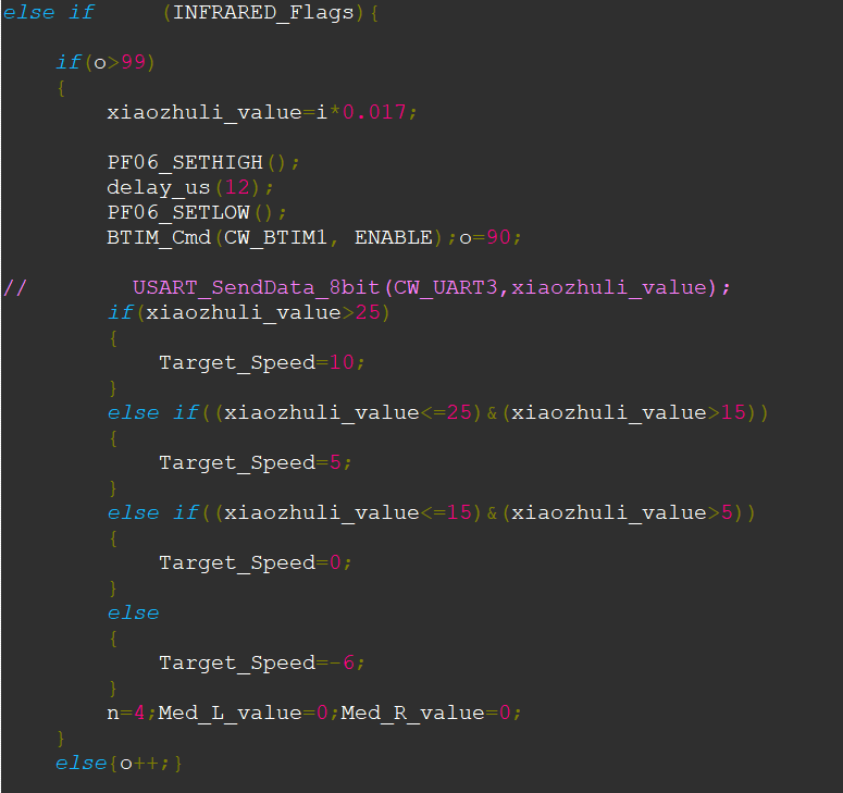
6. Obstacle Avoidance Mode: The code shows that after measuring the distance, different speeds are controlled according to the distance.
7. Voice Mode: Combines time and speed to achieve the corresponding angle. The code explains this; each increment of j equals 10ms of execution with the current force. Therefore, executing the same force for different durations results in different angles.

V. Improve the mechanical structure:
Disassemble and optimize the structure to align the axles of both wheels, minimize the height to lower the center of gravity, and customize an acrylic shell to neatly organize exposed wires for a more aesthetically pleasing appearance.
VI. Adjusting Parameters and PID
1. Adjusting PID:
Four parameters:

(1) Set all to zero
(2) Slowly increase Kp in the vertical loop until the car oscillates at low frequency and high amplitude
(3) Slowly increase Kd in the vertical loop until the car oscillates at high frequency and low amplitude
(4) Multiply by 0.6-0.8 as the final parameter
(5) The relationship between Kp and Ki in the speed loop is 200 times. Kp can be slowly increased by 0.1 from 0.1 to see the effect. If it accelerates and falls, add a negative sign to both coefficients until the ideal effect is achieved.
2. Adjusting speed and other parameters:
Adjust the parameters mentioned above, such as the forward and backward speed in Bluetooth mode, the turning force in voice mode, the speed change degree in obstacle avoidance mode, etc.


 京公网安备 11010802033920号

 177-007-15P6FH4-01


